Note: Descriptions are shown in the official language in which they were submitted.
CA 02722838 2010-10-26
WO 2009/134158 PCT/RU2008/000267
METHOD FOR MONITORING FLOOD FRONT MOVEMENT DURING
FLOODING OF SUBSURFACE FORMATIONS
Field of the invention
This invention relates generally to methods for monitoring directional flood
front movement during oil recovery and more specifically to methods for
monitoring flood front movement of flooding agent injected into subsurface
formations.
The most widely used recovery technique is injection of a flooding agent,
for example, water into an oil-bearing reservoir. As water moves through the
reservoir, it acts to displace oil therein to a production system composed of
one or
more wells through which the oil is recovered.
Water flooding depends on the ability of injected water to displace the oil
remaining in the reservoir. The effectiveness of water flooding is very much
dependent on the hydrodynamic properties of the reservoir (permeability field,
hydrodynamic connections, etc), which remain largely unknown during the whole
production period.
In performing a flooding operation it is important to monitor the progress of
the flood front to determine the movement thereof. Due to formation
characteristics, the flood front does not move in uniform fashion from the
injection wells toward the production well. Further, subsurface formations may
contain high-permeability streaks which allow injected water to break through
the
oil into the production well. The result of such a breakthrough is the
production
from the well of water while significant oil may remain in the formations.
Background art
CA 02722838 2013-02-07
52759-39
2
In the prior art, various methods have been utilized to monitor the progress
of a flood front in oil recovery operations. The first is to track the amount
of oil
and water recovered in production wells and to compare that to the quantity of
water being injected into the system. Then computer models are created which
include known information about the formation being flooded. The disadvantage
of only monitoring the flow rates is that if the formation is not homogeneous
then
valuable pockets of hydrocarbon might not be recovered.
The other method is disclosed in U.S. Pat. No. 3,874,451. It provides for
the detection of the arrival of the flood front by monitoring the pressure
change in
boreholes. This method requires that the boreholes used for pressure
monitoring
must be uncased. In a production reservoir this can require the removal of
casing
already present in the boreholes or the drilling of new, uncased boreholes.
Then, U.S. Pat. No. 4,085,798, discloses a method for monitoring the flood
front profile during water flooding by adding a tracer element having a
characteristic gamma ray emission energy to the flood fluid. It is recognized
as a
serious disadvantage to be required to add tracer elements to the flood fluid
prior
to injection. Since this method is only directed to detecting elements in the
injection fluid it does not provide an indication of flood front movement
until the
fluid flood front reaches or nearly reaches the monitor boreholes.
Accordingly, the present invention overcomes the deficiencies of the prior
art by providing an environmentally friendly high resolution method for
monitoring the flood front movement.
CA 02722838 2014-06-12
52759-39
2a
Summary of the invention
According to an aspect of the present invention, there is provided a method
for
monitoring a flood front movement through a porous medium comprising detecting
an electric
conductivity or magnetic permeability or both, or their combination with
acoustic impedance
of the medium, injecting a flooding agent into the medium, the flooding agent
being a highly
dispersed gas-liquid mixture having size of gas bubbles not exceeding an
average diameter of
the pores of said medium, detecting the electric conductivity or magnetic
permeability or both
or their combination with acoustic impedance of the medium at the same area
after flooding
and monitoring the flood front movement by registering changes in the electric
conductivity
or magnetic permeability or both or their combination with acoustic impedance
of the medium
caused by the arrival of said flood front.
According to a further aspect of the present invention, there is provided a
method for monitoring flood front movement during flooding through a
subsurface formation
located between at least one production well and at least one injection well
during oil recovery
operations comprising detecting an electric conductivity or magnetic
permeability or both or
their combination with acoustic impedance of said formation, injecting a
flooding agent into
said formation through at least one injection well thus forcing reservoir oil
movement toward
at least one production well, the flooding agent being a highly dispersed gas-
liquid mixture
having size of gas bubbles not exceeding an average diameter of the pores of
said formation,
detecting the electric conductivity or magnetic permeability or both or their
combination with
acoustic impedance of the formation at the same area after flooding, and
monitoring the flood
front movement by registering changes in the electric conductivity or magnetic
permeability
or both or their combination with acoustic impedance of the formation caused
by the arrival of
said flood front.
According to another aspect of the invention there is provided a method for
monitoring a flood front movement through a subsurface formation located
between at least
one production well and at least one injection well during oil recovery
operations comprising
detecting physical properties of said formation, injection of a flooding agent
into said
formation through at least one injection well thus forcing
CA 02722838 2013-02-07
52759-39
3
reservoir oil movement toward at least one production well, the flooding agent
being a highly dispersed gas-liquid mixture having size of gas bubbles not
exceeding an average diameter of the pores of said oil-bearing reservoir,
detecting
the same physical properties of the formation at the same area after flooding
and
monitoring the flood front profile by registrating changes in the physical
properties of the formation caused by the arrival of said flood front.
According to another aspect of the present invention there is provided a
method for
monitoring the movement of a flood front through a subsurface formation
comprising time lapse detecting of the physical properties of the formation by
acoustic and/or by deep electromagnetic, and/or by gravimetric and/or by other
means, which makes it possible to accurately monitor the flood front movement
including detecting high-permeability zones and monitoring of the flood front
profile.
According to yet another aspect of the present invention there is provided a
method for
. monitoring the movement of a flood front in which time lapse detecting of
the
physical properties of the formation includes acoustic, electromagnetic or
other
fields induction by the sources located at the surface or/and in at least one
well
and registration of the signals y the receivers located at the surface or/and
in the
well.
According to still another aspect of the present invention there is provided a
method for
monitoring the movement of a flood front traveling through a subsurface
formation wherein said physical properties include acoustic impedance and/or
electric conductivity and/or magnetic permittivity.
According to a further aspect of the present invention there is provided a
method for
monitoring the movement of a flood front wherein there is a sequential
injection
of a highly dispersed gas-liquid mixture and conventional flooding agent
without
gas, so the gas bubbles can trace successive fluid fronts.
Brief description of the drawings
CA 02722838 2010-10-26
WO 2009/134158 PCT/RU2008/000267
4
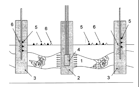
Figure 1 is a schematic diagram of an injection well and the production
wells illustrating the monitoring of a flood front in accordance with the
present
invention.
Description of the preferred embodiment of the invention
Referring now to FIG. 1, there is illustrated a section of a subsurface porous
formation 1 in which oil recovery is undertaken. The formation 1 is penetrated
by
at least one injection well 2 and the production wells 3. It should be
understood
that the number of injection wells and production wells illustrated is
exemplary
only, and that the actual number will differ in accordance with the size of
the
reservoir to undergo water flooding.
A dispergator 4, which produces a highly dispersed gas-liquid mixture
having size of gas bubbles not exceeding an average diameter of the pores of
said
oil-bearing reservoir (for instance, 10-6 m), is located at the surface or in
the
wellbore of the injection wells used in a conventional way. Dispergator could
operate continuously or in an operator specified regime. Highly dispersed gas-
liquid mixture is injected into the permeable formation and propagates along
the
flow path in a porous media. The mixture can consist, for example, of water as
a
liquid and methane, nitrogen or other insoluble gas as a dispersed gas. The
flood
front expands radially from injection well 2 driving the oil in the producing
formations toward producing wells 3. When the gas bubbles are sufficiently
small
(¨micrometers or nanometers), they can survive as a dispersed phase inside
liquid,
while the gas-liquid mixture is propagating though the formation. Due to the
contrast in physical properties between pure flooding fluids (water, polymer
or
others) and highly dispersed gas-liquid mixtures, time lapse monitoring of the
changes in physical properties of the reservoir is possible with acoustic,
electromagnetic or other fields induced by the sources 5 located at the
surface
or/and in the wells or naturally inside the reservoir and registered by the
receivers
6 located at the surface or/and in the wells. Dynamic changes in physical
CA 02722838 2010-10-26
WO 2009/134158 PCT/RU2008/000267
properties registered by receivers 6 are caused by the movement of highly
dispersed gas-liquid mixture. The receivers 6 can be located at the surface or
in
the wells. Thus, for example, the flood front changes such physical properties
as
acoustic impedance, electric conductivity and magnetic permittivity. The
measurements are captured sequentially at the same area at different moments
of
time to monitor changes in the physical properties during the flooding
operation.
By establishing the time-series of physical properties detection the progress
of the
flood front through the formation can be monitored.
As an example, a typical procedure for 3D time-lapse seismic survey
application could be considered as follows: (a) at a certain time after
production
start-up a 3D seismic is made in the vicinity of this well, (b) process data
in a
conventional manner to extract data of particular interest, e.g. amplitudes of
seismic waves , travel times, maps, cubes, etc (c) inject high-dispersed water-
gas
mixture for duration of time, required to achieve the specified distance from
the
injection well, (d) run a 3D seismic at the same area to evaluate the
difference in
elastic field detected in step a) and interpretation results of step (b), (e)
data of
steps (a), (b) and (d) are used to extract information on the special
distribution of
the front which allow to reveal the information about the reservoir structure.
Size of the gas bubbles, distribution in space and over the time depends on
peculiarities of the porous media and could be used as additional information
about the reservoir properties. Monitoring of the changes in gas/oil ratio
(GOR) in
production wells provides information about the connectivity of the reservoir.
The injection of gas-liquid mixture can be performed periodically (followed by
usual water flooding), so the gas bubbles can trace successive water fronts.
Besides, this method can be applied for imaging inner rock structure and
characterizing displacement process during the flow through the core in a lab.
While the invention has been described with respect to a preferred
embodiments, those skilled in the art will devise other embodiments of this
invention which do not depart from the scope of the invention as disclosed
therein.
CA 02722838 2010-10-26
WO 2009/134158 PCT/RU2008/000267
6
Accordingly the scope of the invention should be limited only by the attached
claims.