Some of the information on this Web page has been provided by external sources. The Government of Canada is not responsible for the accuracy, reliability or currency of the information supplied by external sources. Users wishing to rely upon this information should consult directly with the source of the information. Content provided by external sources is not subject to official languages, privacy and accessibility requirements.
Any discrepancies in the text and image of the Claims and Abstract are due to differing posting times. Text of the Claims and Abstract are posted:
| (12) Patent Application: | (11) CA 2722930 |
|---|---|
| (54) English Title: | DISPENSER FOR POUCHED CONTENTS |
| (54) French Title: | DISTRIBUTEUR POUR CONTENUS EN SACHETS |
| Status: | Deemed Abandoned and Beyond the Period of Reinstatement - Pending Response to Notice of Disregarded Communication |
| (51) International Patent Classification (IPC): |
|
|---|---|
| (72) Inventors : |
|
| (73) Owners : |
|
| (71) Applicants : |
|
| (74) Agent: | SMART & BIGGAR LP |
| (74) Associate agent: | |
| (45) Issued: | |
| (86) PCT Filing Date: | 2009-06-25 |
| (87) Open to Public Inspection: | 2010-01-07 |
| Examination requested: | 2012-05-03 |
| Availability of licence: | N/A |
| Dedicated to the Public: | N/A |
| (25) Language of filing: | English |
| Patent Cooperation Treaty (PCT): | Yes |
|---|---|
| (86) PCT Filing Number: | PCT/US2009/048568 |
| (87) International Publication Number: | US2009048568 |
| (85) National Entry: | 2010-10-28 |
| (30) Application Priority Data: | ||||||
|---|---|---|---|---|---|---|
|
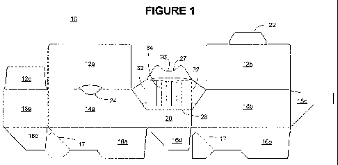
Disclosed is a dispenser for dispensing a continuous strip of pouches. The
dispenser comprises a box with right
(14a) and left (14b) side panels wherein one of the side panels includes a
tuck flap insert (24), a rear panel (18a) and a rear panel
glue flap (18b), a pair of bottom closure panels (16a, 16b) and bottom closure
flaps (16c, 16d), a pair of top closure panels (12a,
12b) and a top closure flap (12c) wherein one of the top panels includes a top
tuck flap (22) adapted to fit into the tuck flap insert
(24), and a front section (20). The front section includes lower and upper
front panels and a gate flap (26). The gate flap touches
one of the top closure panels such that the strip of pouches within the box
can be dispensed out the front section and held in place
by the gate flap.
L'invention porte sur un distributeur pour distribuer une bande continue de sachets. Le distributeur comprend une boîte pourvue de panneaux latéraux droit (14a) et gauche (14b), l'un des panneaux latéraux comprenant un insert de rabat repliable (24), un panneau arrière (18a) et un rabat doté de colle de panneau arrière (18b), une paire de panneaux de fermeture inférieurs (16a, 16b) et de rabats de fermeture inférieurs (16c, 16d), une paire de panneaux de fermeture supérieurs (12a, 12b) et un rabat de fermeture supérieur (12c), l'un des panneaux supérieurs comprenant un rabat repliable supérieur (22) apte à s'adapter dans l'insert de rabat repliable (24), et une section avant. La section avant comprend des panneaux avant inférieurs et supérieurs et un rabat doté dune encoche (26). Le rabat doté dune encoche touche l'un des panneaux de fermeture supérieurs, de telle sorte que la bande de sachets à l'intérieur de la boîte peut être distribuée à partir de la section avant et maintenue en place par le rabat doté dune encoche.
Note: Claims are shown in the official language in which they were submitted.
Note: Descriptions are shown in the official language in which they were submitted.
2024-08-01:As part of the Next Generation Patents (NGP) transition, the Canadian Patents Database (CPD) now contains a more detailed Event History, which replicates the Event Log of our new back-office solution.
Please note that "Inactive:" events refers to events no longer in use in our new back-office solution.
For a clearer understanding of the status of the application/patent presented on this page, the site Disclaimer , as well as the definitions for Patent , Event History , Maintenance Fee and Payment History should be consulted.
| Description | Date |
|---|---|
| Application Not Reinstated by Deadline | 2014-06-25 |
| Time Limit for Reversal Expired | 2014-06-25 |
| Deemed Abandoned - Failure to Respond to Maintenance Fee Notice | 2013-06-25 |
| Letter Sent | 2012-05-22 |
| Request for Examination Received | 2012-05-03 |
| All Requirements for Examination Determined Compliant | 2012-05-03 |
| Request for Examination Requirements Determined Compliant | 2012-05-03 |
| Inactive: Cover page published | 2011-01-21 |
| Inactive: Notice - National entry - No RFE | 2010-12-20 |
| Inactive: First IPC assigned | 2010-12-17 |
| Inactive: IPC assigned | 2010-12-17 |
| Application Received - PCT | 2010-12-17 |
| National Entry Requirements Determined Compliant | 2010-10-28 |
| Application Published (Open to Public Inspection) | 2010-01-07 |
| Abandonment Date | Reason | Reinstatement Date |
|---|---|---|
| 2013-06-25 |
The last payment was received on 2012-06-08
Note : If the full payment has not been received on or before the date indicated, a further fee may be required which may be one of the following
Patent fees are adjusted on the 1st of January every year. The amounts above are the current amounts if received by December 31 of the current year.
Please refer to the CIPO
Patent Fees
web page to see all current fee amounts.
| Fee Type | Anniversary Year | Due Date | Paid Date |
|---|---|---|---|
| Basic national fee - standard | 2010-10-28 | ||
| MF (application, 2nd anniv.) - standard | 02 | 2011-06-27 | 2011-06-03 |
| Request for examination - standard | 2012-05-03 | ||
| MF (application, 3rd anniv.) - standard | 03 | 2012-06-26 | 2012-06-08 |
Note: Records showing the ownership history in alphabetical order.
| Current Owners on Record |
|---|
| MEADWESTVACO CORPORATION |
| Past Owners on Record |
|---|
| MICHAEL WESTON |
| ZANE PETERSON |

