Note: Descriptions are shown in the official language in which they were submitted.
CA 02722984 2010-10-28
WO 2009/135140 PCT/US2009/042543
SELF EXPANDING ELECTRODE CUFF
TECHNICAL FIELD
[001] The invention relates generally to an implantable stimulation system for
stimulating and monitoring soft tissue in a patient, and more particularly,
the
invention relates to an expandable electrode cuff for positioning an electrode
of an
implantable stimulation system about a nerve for stimulation and/or monitoring
of
nerve tissue.
BACKGROUND
[002] Sleep apnea generally refers to the cessation of breathing during sleep.
One type of sleep apnea, referred to as obstructive sleep apnea (OSA), is
characterized by repetitive pauses in breathing during sleep due to the
obstruction
and/or collapse of the upper airway, and is usually accompanied by a reduction
in
blood oxygenation saturation.
[003] One treatment for obstructive sleep apnea has included the delivery of
electrical stimulation to the hypoglossal nerve, located in the neck region
under the
chin. Such stimulation therapy activates the upper airway muscles to maintain
upper
airway patency. In treatment of sleep apnea, increased respiratory effort
resulting
from the difficulty in breathing through an obstructed airway is avoided by
synchronized stimulation of an upper airway muscle or muscle group that holds
the
airway open during the inspiratory phase of breathing. For example, the
genioglossus muscle is stimulated during treatment of sleep apnea by a cuff
electrode place around the hypoglossal nerve.
[004] Because of the significant amount of movement in multiple directions
that
can take place under the chin, positioning an electrode to enable stimulation
of the
hypoglossal nerve becomes a significant challenge. On the one hand, placement
of
the electrode and lead in close proximity to the hypoglossal nerve can result
in
irritation to the nerve as a result of normal motion of the chin and neck,
while on the
other hand, without close adherence to the nerve, buildup of connective tissue
between the nerve and the electrode and lead can occur, causing low
thresholds,
thereby reducing the effectiveness of the delivered stimulation by the device.
CA 02722984 2010-10-28
WO 2009/135140 PCT/US2009/042543
[005] Another challenge in placing an electrode for nerve stimulation therapy
relates to the tendency of the hypoglossal nerve to swell, which can result in
the
nerve being strangled by the electrode and lead. In addition, once the
electrode cuff
has initially been implanted, fibrosis tends to cause the location of the
electrode cuff
to become more fixed. Therefore, the first month post implant is critical to
keep the
electrode cuff properly positioned on the nerve, while at the same time it is
important
not to "suffocate" a swelling nerve. An additional challenge in placing the
electrode
for nerve stimulation results from the fact that stimulation currents need to
be
confined to the hypoglossal nerve in order to prevent other nearby nerves or
muscles
from being stimulated, which results in patient discomfort and loss of sleep.
Therefore, what is needed is an improved electrode cuff that enables
positioning of
an electrode about a nerve.
BRIEF DESCRIPTION OF THE DRAWINGS
[006] Aspects and features of the present invention will be appreciated as the
same becomes better understood by reference to the following detailed
description
of the embodiments of the invention when considered in connection with the
accompanying drawings, wherein:
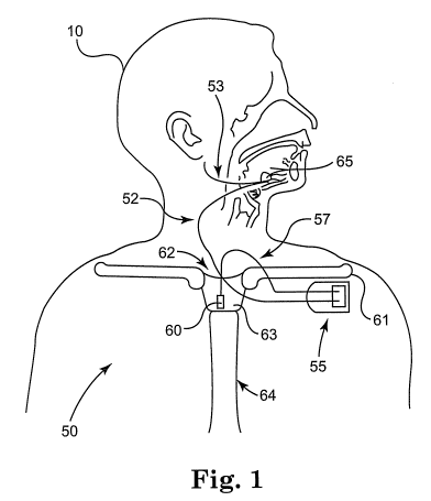
[007] FIG. 1 is a schematic diagram of an implantable stimulation system that
includes a self-expanding nerve cuff according to an embodiment of the
invention;
[008] FIG. 2 is a side view of a lead utilized in an implantable stimulation
system
according to an embodiment of the invention;
[009] FIG. 3 is a front view of an expandable electrode cuff according to an
embodiment of the invention;
[010] FIG. 4 is a front view of the expandable cuff of FIG. 3 in an
intermediate
open position according to an embodiment of the invention;
[011] FIG. 5 is a front view of the expandable electrode cuff of FIG. 3 in a
fully
open position according to an embodiment of the invention;
[012] FIGS. 6 is a schematic diagram illustrating positioning of an expandable
electrode cuff over a desired nerve according to an embodiment of the
invention;
CA 02722984 2010-10-28
WO 2009/135140 PCT/US2009/042543
[013] FIG. 7 is a front view of an expandable electrode cuff positioned about
a
nerve in an intermediate open position according to an embodiment;
[014] FIG. 8 is a front view of an expandable electrode cuff positioned about
a
nerve in a fully engaged position according to an embodiment;
[015] FIG. 9 is a front view of an expandable electrode cuff positioned around
a
nerve according to an embodiment of the invention;
[016] FIG. 10 is a front view of an expandable electrode cuff according to an
embodiment of the invention;
[017] FIG. 11 is a front view of the expandable cuff of FIG. 10 in an
intermediate
open position according to an embodiment of the invention;
[018] FIG. 12 is a front view of the expandable electrode cuff of FIG. 10 in a
fully
open position according to an embodiment of the invention;
[019] FIG. 13 is a front view of an expandable electrode cuff positioned about
a
nerve in an intermediate open position according to an embodiment;
[020] FIG. 14 is a front view of an expandable electrode cuff positioned about
a
nerve in a fully engaged position according to an embodiment;
[021] FIG. 15 is a front view of an expandable electrode cuff positioned
around a
nerve according to an embodiment of the invention;
[022] FIG. 16 is a top view of an expandable electrode cuff according to an
embodiment of the invention in the fully open position;
[023] FIG. 17 is a top view of an expandable electrode cuff according to an
embodiment of the invention in the fully open position;
[024] FIG. 18 is a top view of an expandable electrode cuff according to an
embodiment of the invention in the fully open position; and
[025] FIGS. 19-21 are front views of an expandable electrode cuff according to
embodiments of the invention.
CA 02722984 2010-10-28
WO 2009/135140 PCT/US2009/042543
DESCRIPTION OF EMBODIMENTS
[026] The following detailed description is merely exemplary in nature and is
not
intended to limit the invention or the application and uses of the invention.
Furthermore, there is no intention to be bound by any expressed or implied
theory
presented in the preceding technical field, background, brief summary or the
following detailed description.
[027] FIG. 1 is a schematic diagram of an implantable stimulation system that
includes a self-expanding nerve cuff according to an embodiment of the
invention.
As illustrated in FIG.1, an example of an implantable stimulation system
according to
one embodiment of the invention includes an implantable pulse generator (IPG)
55,
capable of being surgically positioned within a pectoral region of a patient
10, and a
stimulation lead 52 electrically coupled with the IPG 55 via a connector (not
shown)
positioned within a connection port of the IPG 55. The lead 52 includes an
electrode
or electrode system 65 and extends from the IPG 55 so that the electrode
system 65
is position around a desired nerve, such as the hypoglossal nerve 53 of the
patient
10, to enable stimulation of the nerve 53, as described below in detail. An
exemplary
implantable stimulation system in which lead 52 may be utilized, for example,
is
described in U.S. Patent No. 6,572,543 to Christopherson et al., incorporated
herein
by reference in its entirety, and further includes a sensor lead 57
electrically coupled
to the IPG 55 and extending from the IPG 55 so that a sensor or transducer 60
can
be positioned in the patient 10 for sensing of respiratory effort.
[028] The sensor 60 may be a pressure sensor that is surgically implanted in a
region that has pressure continuity with the intrapleural space, such as the
suprasternal notch, the space between the trachea and esophagus, or by being
attached to either of the trachea or esophagus. The sensor 60 may also be
positioned intercostally, or secured in a position for sensing pressure at the
posterior
side of the manubrium. The suprasternal notch 62 and manubrium 63 of the
sternum 64 are well known structures on the upper chest that are in anatomical
continuity with the intrapleural space. It is also well known that changes in
intrapleural pressure provide a characteristic respiratory effort waveform.
CA 02722984 2010-10-28
WO 2009/135140 PCT/US2009/042543
[029] The location for placement of the sensor 60 is, at least in part, chosen
as a
function of a delay, i.e. the propagation time associated with a pressure
waveform
characteristic of respiratory effort propagating from the respiratory point of
origin to
the sensor position. The chosen location is also a function of the amount of
filtering
necessary to achieve a usable sensed signal at a particular location, i.e. the
amount
of filtering that is necessary to remove waveforms other than the waveform
associated with the desired sensed characteristic, such as the filtering
required to
remove cardiac waveform activity, for example. The positioning of the sensor
60
enables the IPG 55 to receive respiratory effort waveform information utilized
to
determine increased respiratory effort, which is then used by the IPG 55 to
control
delivery of therapy in response to determined increases in respiratory effort.
[030] FIG. 2 is a side view of a lead utilized in an implantable stimulation
system
according to an embodiment of the invention. As illustrated in FIG. 2, a lead
100
according to one embodiment includes a lead body 102 extending from a proximal
end 104 to a distal end 106, with a connector 108 positioned at the proximal
end 104
for electrically connecting the lead 100 to the IPG 55. An expandable
electrode cuff
110, positioned at the distal end 106 of the lead body 102, is capable of
being
positioned around a nerve, such as a hypoglossal nerve for example, in order
to
strategically locate one or more electrodes 112 embedded within the electrode
cuff
110 so as to be adjacent to the nerve when the electrode cuff 110 is
positioned
around the nerve. Conductors (not shown) are positioned within the lead body
102
to electrically connect the electrodes 112 and the connector 108 so that the
electrodes 112 are electrically coupled to the IPG 55 via respective connector
pins
114 of the connector 108, as is known in the art.
[031] FIG. 3 is a front view of an expandable electrode cuff according to an
embodiment of the invention. As illustrated in FIG. 3, according to one
embodiment,
the expandable electrode cuff 110 is a single, unitary molded piece that
includes a
base portion 120 having a top wall 122 and a bottom wall 124 extending from a
first
side wall 126 to a second side wall 128. A first flange member 130 extends
from a
proximal end 131 to a distal end 312, and is located at the top wall 122 of
the base
portion 120 to extend from the first side wall 126 to the distal end 132. A
second
flange member 134 extends from a proximal end 135, and is located at the top
wall
CA 02722984 2010-10-28
WO 2009/135140 PCT/US2009/042543
122 of the base portion 120 to extend from the second side wall 128 to the
distal end
136. As will be described below, the electrode cuff 110 is expandable both
during
implantation of the lead 100 and electrode cuff 110, and after the electrode
cuff 110
is positioned around a desired nerve for delivery of electrical stimulation
therapy to
the nerve.
[032] During it's normal, unbiased state, prior to insertion around the nerve,
the
electrode cuff 110 is in a fully engaged position, shown in FIG. 3, in which
the dsital
end 132 of the first flange member 130 is positioned adjacent to and may
engage
against the second side wall 128 at a location below the proximal end 135 of
the
second flange member 134 and below the top wall 122 of the base portion 120,
and
the distal end 136 of the second flange member 134 is positioned at a location
above
the proximal end 131 of the first flange member 130 and above the top wall 122
of
the base portion 120 along the first side wall 126.
[033] The first flange member 130 has a length greater than the second flange
member 134 so that when the electrode cuff 110 is in the fully engaged
position, the
first flange member 130 and the second flange member 134 form a lumen 140 for
receiving a nerve therein, with an inner side wall 141 of the second flange
member
134 forming an inner wall 142 of the lumen 140 so as to position the
electrodes 112
(shown in FIG. 2), which are embedded within the second flange member 134,
adjacent to the nerve (not shown in FIG. 3).
[034] In addition, when the electrode cuff 110 is in the fully engaged
position, an
inner side wall 144 of the first flange member 130 is positioned over and
engages
against an outer side wall 146 of the second flange member 134, and therefore
an
outer wall 148 of the first flange member 130 forms an outer wall 143 of the
lumen
140. In this way, when the electrode cuff 110 is in the fully engaged position
shown
in FIG. 3, both the first flange member 130 and the second flange member 134
extend over the base portion 120, the first flange member 130 forms an outer
portion
of the electrode cuff 110, and the second flange member 134 forms an inner
portion
of the electrode cuff 110 for engaging the nerve. Depending on the size of the
nerve, once positioned about a nerve, the electrode cuff 110 may be in either
the
fully engaged position of FIG. 3 or in a partially fully engaged position,
wherein the
distal end 132 of the first flange member 130 may be spaced from rather than
CA 02722984 2010-10-28
WO 2009/135140 PCT/US2009/042543
engaged against the second side wall 128, and the distal end 136 of the second
flange member 134 may be spaced from rather than aligned with the first side
wall
126 at the top wall 122 of the base portion 120, as will be described below.
[035] FIG. 4 is a front view of the expandable cuff of FIG. 3 in an
intermediate
open position according to an embodiment of the invention. As illustrated in
FIG. 4,
during positioning of the electrode cuff 110 over the desired nerve so that
the nerve
can be properly located within the lumen 140, the electrode cuff 110 is
advanced
from the fully engaged position shown in FIG. 3, to an intermediate position
shown in
FIG. 4, in which the distal end 132 of the first flange member 130 is advanced
away
from the second side wall 128, and the inner side wall 144 of the first flange
member
130 is advanced away from the outer side wall 146 of the second flange member
134 so that the distal end 132 extends outward from and along the first side
wall 126
of the base portion 120. As a result, when the electrode cuff 110 is in the
intermediate open position, the first flange member 130 is not positioned so
as to
extend over the top wall 122 of the base portion 120, and the distal end 132
is no
longer positioned below the top wall 122 of the base portion 120, while the
second
flange member 134 remains positioned to extend over the top wall 122 of the
base
portion 120 with the distal end 136 of the second flange member 134 positioned
above the proximal end 131 of the first flange member 130. In addition, the
inner
side wall 144 of the first flange member 130 is no longer positioned over and
adjacent to the outer side wall of 146 of the second flange member 134 when
the
cuff 110 is in the intermediate open position of FIG. 4.
[036] FIG. 5 is a front view of the expandable electrode cuff of FIG. 3 in a
fully
open position according to an embodiment of the invention. As illustrated in
FIG. 5,
once the electrode cuff 110 is in the intermediate open position, the distal
end 136 of
the second flange member 134 is advanced away from the top wall 122 of the
base
portion 120 and the first side wall 126 so that rather than being positioned
above the
proximal end 131 of the first flange member 130, the distal end 136 of the
second
flange member 134 extends outward from the second side wall 128 so that the
second flange member 134 does not extend over the second side wall 128 of the
base portion 120, resulting in the inner wall 142 of the second flange member
134 no
longer forming the lumen 140 when the cuff is in the fully open position of
FIG. 5. As
CA 02722984 2010-10-28
WO 2009/135140 PCT/US2009/042543
a result, when the electrode cuff 110 is in the fully open position, neither
the first
flange member 130 nor the second flange member 134 are positioned so as to
extend over or near the top wall 122 of the base portion 120 of the electrode
cuff
110, the inner side wall 144 of the first flange member 130 is no longer
positioned
over or near an outer side wall 146 of the second flange member 134, and the
inner
side wall 141 of the second flange member 134 no longer forms the inner wall
142 of
the lumen 140. In this way, by enabling the electrode cuff 110 to be advanced
between the fully engaged position, the intermediate open position, and the
fully
open position, the invention enables the cuff 110 to be more easily positioned
over a
nerve during implantation of the lead 100, as described below.
[037] FIG. 6 is a schematic diagram illustrating positioning of an expandable
electrode cuff over a desired nerve according to an embodiment of the
invention. As
illustrated in FIG. 6, during the initial positioning of the lead and
positioning of the
electrode cuff 110 over a nerve, such as over a hypoglossal nerve 200, once
the
nerve 200 has been dissected out over a desired range, such as over 1-3 cm
range,
for example, the electrode cuff 110 is advanced from the normal, fully engaged
position of FIG. 3 to the fully open position of FIG. 5 so that the inner
flange 134 of
the electrode cuff 110 is then inserted under the nerve 200 while in the fully
open
position, until the nerve 200 becomes positioned so as to be aligned with and
against
the top wall 122 of the base portion 120.
[038] The inner flange member 134 is then released so that the inner flange
member 134 becomes positioned around the nerve 200. According to one
embodiment, prior to be advanced from the fully open position to the
intermediate
position, the base portion 120 of the electrode cuff 110 is positioned inward,
towards
the body of the patient. As a result, once positioned under the nerve 200, the
electrode cuff 110 is advanced from the fully open position to the
intermediate open
position (FIG. 4) so that only the second flange member 134 is positioned over
the
top wall 122 of the base portion 120, enclosing the nerve 200. The outer
flange
member 130 is then released to be positioned around the nerve 200, resulting
in the
electrode cuff 110 being advanced from the intermediate open position to a
final
engaged positioned (see FIG. 7), with both the first flange member 130 and the
second flange member 134 being positioned over the top wall 122 of the base
CA 02722984 2010-10-28
WO 2009/135140 PCT/US2009/042543
portion 120, enclosing the nerve 200 within the lumen 140 formed by the flange
members 130 and 134.
[039] FIG. 7 is a front view of an expandable electrode cuff positioned about
a
nerve in an intermediate open position according to an embodiment. As
illustrated in
FIG. 7, depending upon the circumference of the nerve 200, once the nerve 200
is
positioned over the top wall 122 of the base portion 120 of the electrode cuff
110,
and the inner flange member 134 is positioned about the nerve 200 during the
advancement of the electrode cuff 110 from the fully open position of FIG. 5
to the
intermediate open position of FIG. 7, the distal end 136 of the second flange
member
134 may be positioned to be spaced further above the proximal end 131 of the
first
flange member 130 and further away from the first side wall 126 and the top
wall 122
of the base portion 120 than when the electrode cuff 110 is in the
intermediate open
position of FIG. 4. As a result, the size of the lumen 140 can be increased
relative to
when the electrode cuff 110 is in the intermediate open position of FIG. 4 to
accommodate the size of the nerve 200.
[040] FIG. 8 is a front view of an expandable electrode cuff positioned about
a
nerve in a fully engaged position according to an embodiment. Similarly,
during the
advancement of the electrode cuff from the intermediate open position of FIG.
7 to
the fully engaged position during implant of the electrode cuff 110, the
distal end 132
of the outer flange member 130 may be positioned to be spaced further away
from
the second side wall 128 of the base portion 120 than when the electrode cuff
110 is
in the fully engaged position of FIG. 3, and to be above, rather than below
the
proximal end 135 of the second flange member 134 and the top wall 122 of the
base
portion 120, thereby increasing the size of the lumen 140 relative to when the
electrode cuff 110 is in the fully engaged position of FIG. 3 prior to be
implanted to
accommodate the size of the nerve. Therefore, as illustrated in FIGS. 7 and 8,
in
order to accommodate the size of the nerve, the first and second flanges 130
and
134 can be advanced or expanded to increase the diameter of the lumen 140.
[041] FIG. 9 is a front view of an expandable electrode cuff positioned around
a
nerve according to an embodiment of the invention. If the small arteries that
run
along the side of the nerve are overly restricted by the electrode cuff 110,
blood
supply could be inhibited, causing temporary or permanent damage to the nerve.
CA 02722984 2010-10-28
WO 2009/135140 PCT/US2009/042543
The inventors have found that approximately 25 mmHg is the approximate amount
of
pressure that may be applied to the nerve without restricting blood flow. As
illustrated in FIG. 9, according to one embodiment, in order to address the
effects of
swelling of the hypoglossal nerve 200 that may sometimes occur, particularly
after
the initial trauma associated with implanting the electrode cuff 110, the
first and
second flange members 130 and 134 are expandable so that the circumference of
the lumen 140 formed by the electrode cuff 110 is able to increase to
accommodate
increases in the diameter of the nerve 200 that occur subsequent to the
initial
positioning of the expandable electrode cuff 110 about the nerve 200. For
example,
during swelling of the nerve 200 subsequent to implant of the device 100, the
first
flange member 130 and the second flange member 134 expand so that the distal
end 132 of the first flange member 130 becomes positioned to be spaced further
away from the second side wall 128 of the base portion 120, and to be even
further
above, rather than below the proximal end 135 of the second flange member 134
and the top wall 122 of the base portion 120. At the same time, the distal end
136 of
the second flange member 134 becomes positioned to be spaced further above the
proximal end 131 of the first flange member 130 and further away from the
first side
wall 126 and the top wall 122 of the base portion 120, thereby further
increasing the
size of the lumen 140 to accommodate the swelling. As the swelling of the
nerve
200 subsides, the first and second flange members 130 and 134 return towards
the
original fully engaged position about the nerve 200 that occurred at the time
of
implant.
[042] FIG. 10 is a front view of an expandable electrode cuff according to an
embodiment of the invention. As illustrated in FIG. 10, according to another
embodiment, an expandable electrode cuff 310 includes a base portion 320
having a
top wall 322 and a bottom wall 324 extending from a first side wall 326 to a
second
side wall 328, a first flange member 330, a second flange member 334, and a
third
flange member 350. The first flange member 330 is bonded at a proximal end 331
to
the third flange member 350 along a portion of an outer wall 352 of the third
flange
member 350, and extends outward and over the top wall 322 of the base portion
320
from the first side wall 326 to a distal end 332. The second flange member 334
extends outward and over the top wall 322 of the base portion 320 from the
second
side wall 328 to a distal end 336. The third flange member 350 extends outward
at
CA 02722984 2010-10-28
WO 2009/135140 PCT/US2009/042543
the top wall 322 of the base portion 320 from the first side wall 326 to a
distal end
352.
[043] In the expandable electrode cuff 310 of the embodiment of FIG. 10, the
base
portion 320, second flange member 334 and the third flange member 350 are
formed
from a single, unitary molded piece, with the first flange member 330 bonded
to the
molded piece. As will be described below, the electrode cuff 310 is expandable
both
during implantation of the lead 100 and electrode cuff 310, and after the
electrode
cuff 310 is positioned around a desired nerve for delivery of electrical
stimulation
therapy to the nerve, similar to the electrode cuff 110 described above in the
embodiment of FIGS. 3-5.
[044] During it's normal, unbiased state, prior to insertion around the nerve,
the
electrode cuff 310 is in a fully engaged position, shown in FIG. 10, in which
the first
flange member 330 extends outward and over the top wall 322 of the base
portion
320 from the first side wall 326 to the distal end 332, the second flange
member 334
extends outward and over the top wall 322 of the base portion 320 from the
second
side wall 328 to the distal end 336, and third flange member 350 extends
outward at
the top wall 322 of the base portion 320 from the first side wall 326 to the
distal end
352 so that the third flange member 350 does not extend over the top wall 332.
In
addition, while in the fully engaged position, the distal end 332 of the first
flange
member 330 is positioned adjacent to and engaged against an outer side wall
346 of
the second flange member 334 and an outer side wall 347 of the third flange
member 350, and the distal end 336 of the second flange member 334 is
positioned
adjacent to and may be engage against the distal end 352 of the third flange
member 350 at a location along the first flange member 330.
[045] The first flange member 330 has a length greater than the second flange
member 334 so that when the electrode cuff 310 is in the fully engaged
position, the
first, second and third flange members 330, 334 and 350 form a lumen 340 for
receiving a nerve therein, with an inner side wall 341 of the second flange
member
134 and an inner side wall 354 of the third flange member 350 forming an inner
wall
342 of the lumen 340 so as to position the electrodes 112 (shown in FIG. 2),
which
are embedded within the second flange member 334, adjacent to the nerve (not
shown in FIG. 3). In addition, when the electrode cuff 310 is in the fully
engaged
CA 02722984 2010-10-28
WO 2009/135140 PCT/US2009/042543
position, an inner side wall 344 of the first flange member 330 is positioned
over the
outer side wall 346 of the second flange member 334 and the outer side wall
347 of
the third flange member 350, and an outer wall 348 of the first flange member
330
forms an outer wall 343 of the lumen 340. In this way, when the electrode cuff
310 is
in the fully engaged position shown in FIG. 10, both the first flange member
330 and
the second flange member 334 extend over the base portion 320, the first
flange
member 330 forms an outer portion of the electrode cuff 310, and the second
and
third flange members 334 and 350 form an inner portion of the electrode cuff
310 for
engaging the nerve. Depending on the size of the nerve, once positioned about
the
nerve, the electrode cuff 310 may be either in the fully engaged position of
FIG. 10 or
in a partially fully engaged position, wherein the distal end 332 of the first
flange
member 330 may be positioned along the outer side wall 346 of the second
flange
member 334 to be spaced further away from the second side wall 328 than shown
in
FIG. 10, and the distal end 336 of the second flange member 334 may be spaced
further away from and not engaged against the distal end 352 of the third
flange
member 350, as will be described below.
[046] FIG. 11 is a front view of the expandable cuff of FIG. 10 in an
intermediate
open position according to an embodiment of the invention. As illustrated in
FIG. 11,
during positioning of the electrode cuff 310 over the desired nerve so that
the nerve
can be properly located within the lumen 340, the electrode cuff 310 is
advanced
from the fully engaged position shown in FIG. 10, to an intermediate position
shown
in FIG. 11 in which the distal end 332 of the first flange member 330 is
advanced
away from the second side wall 328, and the first flange member 330 is
advanced
away from the second flange member 334 so that the distal end 332 extends
outward in an opposite direction from the first side wall 326 of the base
portion 320.
As a result, when the electrode cuff 310 is in the intermediate open position,
the first
flange member 330 is not positioned so as to extend over the top wall 322 of
the
base portion 320, while the second flange member 334 remains positioned to
extend
over the top wall 322 of the base portion 320, with the distal end 336
adjacent to the
distal end 352 of the third flange member 350. In addition, the inner side
wall 344 of
the first flange member 330 is no longer positioned over and adjacent to the
outer
side wall 346 of the second flange member 334 when the cuff 310 is in the
intermediate open position of FIG. 11.
CA 02722984 2010-10-28
WO 2009/135140 PCT/US2009/042543
[047] FIG. 12 is a front view of the expandable electrode cuff of FIG. 10 in a
fully
open position according to an embodiment of the invention. As illustrated in
FIG. 12,
once the electrode cuff 310 is in the intermediate open position, the distal
end 336 of
the second flange member 334 is advanced away from the distal end 352 of the
third
flange member 350 and the second flange member 334 is advanced to no longer
extend over the top wall 322 of the base portion 320 and the first side wall
326 so
that the distal end 336 extends outward in the opposite direction from the
second
side wall 328, resulting in the inner wall 342 of the second flange member 334
no
longer forming the lumen 340 when the electrode cuff 310 is in the fully open
position
of FIG. 12. As a result, when the electrode cuff 310 is in the fully open
position,
neither the first flange member 330 nor the second flange member 334 are
positioned so as to extend over or near the top wall 322 of the base portion
320 of
the electrode cuff 310, the inner side wall 344 of the first flange member 330
is no
longer positioned over or near the outer side wall 346 of the second flange
member
334, and the inner side wall 341 of the second flange member 334 no longer
forms
the inner wall 342 of the lumen 340.
[048] In this way, by enabling the electrode cuff 310 to be advanced between
the
fully engaged position, the intermediate open position, and the fully open
position,
the electrode cuff 310 can be more easily positioned over a nerve during
implantation of the lead 100, using the same method of implantation as
described
above in FIG. 6, for example. If desired, an adhesive material (not shown)
could be
added to the distal end 352 of the third flange member 350 in order to make a
smoother transition at the distal end 352 and the inner wall 334 of the first
flange
member 330 during positioning of the electrode cuff 310 abouot the nerve.
[049] As can be seen in FIGS. 10-12, the second flange member 334 according to
one embodiment has a first thickness 360 along a proximal end 362 located at
the
top wall 322 of the base portion 120 along the second side wall 328, and a
second
thickness, less than the first thickness 360, at the distal end 336 of the
second flange
member 334, so that the second flange member 334 is tapered in thickness from
the
proximal end 362 to the distal end 336. Similarly, the third flange member 350
has a
first thickness 364 along a proximal end 366 located at the top wall 322 of
the base
portion 320 along the first side wall 326, and a second thickness, less than
the first
CA 02722984 2010-10-28
WO 2009/135140 PCT/US2009/042543
thickness 364, at the distal end 352 of the third flange member 350, so that
the third
flange member 350 is tapered in thickness from the proximal end 366 to the
distal
end 352. While the inner flange member 334 of FIGS. 8-10 is shown to be
tapered,
it is understood that both the inner flange member 334 and the outer flange
member
332 could be formed without being tapered. In addition, it is understood that
the
inner flange member 134 of FIGS. 3-5 may also be tapered as described in the
embodiment of FIGS. 10-12.
[050] The flange members described above may be formed from polyurethane,
silicon or a blend of polyurethane and silicon. Furthermore, according to an
embodiment, one of the flange members could be formed of polyurethane while
the
other is formed of silicon. If formed from silicone, then the durometer of the
flange
material range would be within a range of approximately 40A - 70A. The
thickness
of the flange material could be from approximately 0.005 inches to 0.025
inches.
Nominally, if the flange is formed of a polyurethane having a durometer of
approximately 85A, the flange would be 0.0075 inches thick. In the embodiment
of
FIGS. 10-12, the inner flange 334 is formed from molded polyurethane and the
outer
flange 330 is formed from a portion of a polyurethane tubing. In either
embodiment,
the polyurethane is formed to have a "memory" that enables the flange members
to
be biased towards the fully engaged positioned. The lumen 140, 340 may have an
inner diameter between 0.050 and 0.400 inches, while according to an
embodiment,
the inner diameter is approximately 0.140 inches in the fully engaged
position.
[051] If the inner flange member 134, 334 is tapered, the respective proximal
end
135 and 360 may have a thickness of approximately 0.025 to 0.030 inches, and
the
distal end 136, 336 may have a thickness of approximately 0.001 to 0.010
inches.
This provides a strong mechanical connection to the sidewall and also provides
the
needed thickness to hold and strain relief the electrodes. According to one
embodiment, the distal end 136, 336 has a thickness of 0.005 inches.
Similarly, the
distal end 352 of the third flange member 350 may have a thickness of
approximately 0.001 to 0.010 inches, and according to an embodiment in which
the
distal end 336 of the second flange member 334, the distal end 352 of the
third
flange member would also have a thickness of approximately 0.005 inches.
CA 02722984 2010-10-28
WO 2009/135140 PCT/US2009/042543
[052] FIG. 13 is a front view of an expandable electrode cuff positioned about
a
nerve in an intermediate open position according to an embodiment. As
illustrated in
FIG. 13, depending upon the circumference of the nerve 200, once the nerve 200
is
positioned over the top wall 322 of the base portion 320 of the electrode cuff
310 and
adjacent to the third flange member 350, and the second flange member 334 is
positioned about the nerve 200 during the advancement of the electrode cuff
310
from the fully open position of FIG. 10 to the intermediate open position, the
distal
end 336 of the second flange member 334 may be positioned to be spaced further
above the proximal end 331 of the first flange member 330 and the distal end
352 of
the third flange member 350 than when the electrode cuff 310 is in the
intermediate
open position of FIG. 11. As a result, the size of the lumen 340 can be
increased
relative to when the electrode cuff 310 is in the intermediate open position
of FIG. 11
to accommodate the size of the nerve 200 during positioning of the electrode
cuff
310.
[053] FIG. 14 is a front view of an expandable electrode cuff positioned about
a
nerve in a fully engaged position according to an embodiment. Similarly,
during the
advancement of the electrode cuff 310 from the intermediate open position of
FIG.
13 to the fully engaged position during implant of the electrode cuff 310, the
distal
end 332 of the outer flange member 330 may be positioned along the outer side
wall
346 of the second flange member 334 to be spaced further away from the second
side wall 328 than when the electrode cuff 310 is in the fully engaged
position of FIG.
10, and to be above, rather than below the top wall 332 of the base portion
320. As
a result, the diameter of the lumen 340 is increased relative to when the
electrode
cuff 310 is in the fully engaged position of FIG. 10 prior to being implanted,
to
accommodate the size of the nerve. Therefore, as illustrated in FIGS. 13 and
14, in
order to accommodate the size of the nerve, the first and second flanges 330
and
334 can be advanced or expanded to increase the diameter of the lumen 340.
[054] FIG. 15 is a front view of an expandable electrode cuff positioned
around a
nerve according to an embodiment of the invention. As illustrated in FIG. 15,
according to one embodiment, in order to address the effects of swelling of
the
hypoglossal nerve 200 that may sometimes occur, particularly after the initial
trauma
associated with implanting the electrode cuff 310, the first and second flange
CA 02722984 2010-10-28
WO 2009/135140 PCT/US2009/042543
members 330 and 334 are expandable so that the circumference of the lumen 340
formed by the electrode cuff 310 can be increased to accommodate increases in
the
diameter of the nerve 200 that occur subsequent to the initial positioning of
the
expandable electrode cuff 310 about the nerve 200, as illustrated in FIG. 14.
For
example, during swelling of the nerve 200 subsequent to implant of the device
100,
the first flange member 330 and the second flange member 334 expand so that
the
distal end 332 of the first flange member 330 becomes positioned to be spaced
further away from the second side wall 328 of the base portion 320, and to be
even
further above, rather than below, the top wall 322 of the base portion 320
than when
the electrode cuff 310 was initially positioned about the nerve to the
position
illustrated in FIG. 14. At the same time, the distal end 336 of the second
flange
member 334 becomes positioned to be spaced further above the distal end 352 of
the third flange member 350, and further away from the first side wall 326 and
the
top wall 322 of the base portion 320, thereby further increasing the size of
the lumen
340 to accommodate the swelling. As the swelling of the nerve 200 subsides,
the
first and second flange members 330 and 334 return towards the original fully
engaged position about the nerve 200 that occurred during positioning of the
electrode cuff 310 at the time of implant of the device, such as is
illustrated in FIG.
14.
[055] By forming the first and second flange members, described above, to
extend
over the base member so that each of the flange members extend from a proximal
end located on one side of the base member to a distal end located along the
other
side of the base member, the electrode cuff will continue to be positioned
completely
around the nerve, thereby preventing open gaps from being formed between the
distal ends of the flange members as the nerve swells. Rather, the first and
second
flange members described above enable the necessary expansion of the flange
members to accommodate increasing the diameter of the lumen required for
maintaining the nerve to be completely enclosed within the lumen. In this way,
using
the electrode cuff described above, the opportunity for the nerve to extend
and
extend out of the lumen is decreased, since the electrode cuff is able to more
effectively accommodate such swelling.
CA 02722984 2010-10-28
WO 2009/135140 PCT/US2009/042543
[056] FIG. 16 is a top view of an expandable electrode cuff according to an
embodiment of the invention in the fully open position. As illustrated in FIG.
16,
according to an embodiment, an expandable electrode cuff 410 includes a first
flange member 430 and a second flange member 434 extending from a base portion
420, as described above. Ends 432 and 436 of one or both of the first flange
member 430 and the second flange member 434, respectively, may include having
chamfered corners 435 to prevent the corners 435 from curling during placement
of
the expandable electrode cuff 410 over the nerve, as described above.
[057] FIG. 17 is a top view of an expandable electrode cuff according to an
embodiment of the invention in the fully open position. As illustrated in FIG.
17,
according to an embodiment, an expandable electrode cuff 510 includes a first
flange member 530 and a second flange member 534 extending from a base portion
520, as described above. Ends 532 and 536 of one or both of the first flange
member 530 and the second flange member 534, respectively, may include a
suture
537 attached thereto. For example, one or more holes 539 may be formed along
the
ends or at the respective corners 535 for attaching a suture 537 to the flange
member. The suture 537 is utilized to pull one or both of the flange members
530
and 534 through and under the nerve during positioning of the electrode cuff
510
about the nerve while in the fully open position. In addition, the sutures 537
may
also be utilized to aid in advancing the electrode cuff from the fully engaged
position
to the fully open position prior to placement of the electrode cuff 510. Once
the
expandable electrode cuff 510 is positioned under the nerve, the implanter
merely
releases the hold on the sutures 537 to allow either of the flange members 530
and
534 to be engaged around the nerve, as described above, and the sutures 537
may
then be removed by being cut off from the electrode cuff 510.
[058] According to an embodiment, the sutures 537 may come already attached to
the electrode cuff, or the electrode cuff may only include the holes formed at
one or
more of the ends, so that the implanter merely inserts the sutures in the
desired
holes prior to positioning of the electrode cuff about the nerve.
[059] FIG. 18 is a top view of an expandable electrode cuff according to an
embodiment of the invention in the fully open position. As illustrated in FIG.
18,
CA 02722984 2010-10-28
WO 2009/135140 PCT/US2009/042543
according to an embodiment, an expandable electrode cuff 610 includes a first
flange member 630 and a second flange member 634 extending from a base portion
620, as described above. One or both corners of ends 632 and 636 of one or
both of
the first flange member 630 and the second flange member 634, respectively,
may
include a molded or attached tab 645, that, similar to the sutures of FIG. 17,
are
utilized pull one or both of the flange members 630 and 634 through and under
the
nerve during positioning of the electrode cuff 610 about the nerve while in
the fully
open position. In addition, the tabs 645 may also be utilized to aid is
advancing the
electrode cuff 610 from the fully engaged position to the fully open position
prior to
placement of the electrode cuff 610. Once the expandable electrode cuff 610 is
positioned under the nerve, the implanter merely releases the hold on the tabs
645
to allow either of the flange members 630 and 634 to be engaged around the
nerve,
as described above. In addition, an embodiment may include a combination of
the
tabs 645 and one or more holes 639 formed at the respective corners 635 of the
ends 632 and 636 to aid in placement of the electrode cuff about the nerve. If
the
use of sutures to aid in implant is desired, the implanter may merely inserts
a suture
in the desired hole 639.
[060] FIGS. 19-21 are front views of an expandable electrode cuff according to
embodiments of the invention. As illustrated in FIGS. 19-21, other
configurations of
the flange members may also be utilized. An electrode cuff 410 according to
one
embodiment may include a second flange member 434 and a third flange member
450 formed to have any desired lengths to enable the respective ends 436 and
452
to be positioned at any desired location within the lumen 440. For example, as
illustrated in FIG. 19, the distal end 436 of the second flange member 434 and
the
distal end 452 of the third flange member 450 may be positioned further above
the
first side wall 426 than in the exemplary illustration of FIG. 10. In
addition, in another
embodiment the length of the first flange member 430 may be increased so that
the
first flange member 430 extends over the top wall 422 of the base portion 420,
around the second flange member 434 and under the bottom wall 424 of the base
member 420, with the distal end 432 of the first flange member 430 being
positioned
below the proximal end 431 of the first flange member 430 along the first side
wall
426.
CA 02722984 2010-10-28
WO 2009/135140 PCT/US2009/042543
[061] As illustrated in FIG. 20, according to another embodiment, the length
of a
first flange member 530 may be even further increased so that the first flange
member 530 extends over the top wall 522 of the base potion 520, around the
second flange member 534, under the bottom wall 524 of the base member 520 and
over the first flange member 530 along the proximal end 531 of the first
flange
member 530, with the distal end 532 of the first flange member 530 being
positioned
above the proximal end 531 of the first flange member 530 along the first side
wall
426.
[062] As illustrated in FIG. 21, according to yet another embodiment, the
second
flange member 634 and the third flange member 650 may be formed to be
symmetrical, with the distal end 636 of the second flange member 634
positioned
approximately the same distance above the second side wall 628 of the base
portion
620 as the distal end 652 of the third flange member 650 is positioned above
the first
side wall 626 of the base portion 620. In addition, the length of the first
flange
member 630 may be increased so that the first flange member 630 extends over
the
top wall 622 of the base portion 620 a multiple number of times, around the
second
flange member 434 and under the bottom wall 424 of the base member 420 the
multiple number of times, with the distal end 432 of the first flange member
430
being positioned at any location around the electrode cuff 610, such as above
the
proximal end 431 of the first flange member 430 along the first side wall 426,
as
shown in FIG. 21.
[063] While at least one exemplary embodiment has been presented in the
foregoing detailed description, it should be appreciated that variations
exist. It
should also be appreciated that the exemplary embodiment or exemplary
embodiments are only examples, and are not intended to limit the scope,
applicability, or configuration of the invention in any way. Rather, the
foregoing
detailed description will provide those skilled in the art with a convenient
road map
for implementing the exemplary embodiment or exemplary embodiments. It should
be understood that various changes can be made in the function and arrangement
of
elements without departing from the scope of the invention as set forth in the
appended claims and the legal equivalents thereof.