Note: Descriptions are shown in the official language in which they were submitted.
CA 02723231 2010-10-28
1
JOINING ELEMENT BETWEEN MODULES FOR CONSTRUCTIONS
The present invention relates to a joining element
for construction, especially for transferring loads
between modules, preferably prefabricated and made of
reinforced concrete, provided with a material which when
used under certain conditions allows flexible, reliable,
lasting and easily installed joints to be made and which,
when said prefabricated modules are stacked, contributes
towards making buildings of considerable height.
BACKGROUND OF THE INVENTION
Known in the art are modular prefabricated
concrete elements for dwellings.
Such elements are generally conceived for
arranging contiguously and stacked in order finally to
form buildings several storeys high.
For structural and constructional reasons it is
necessary to provide vertical and horizontal joints
between contiguous elements in the vertical and horizontal
directions, respectively.
One common solution is to use rigid joining
elements, generally made of steel, so as to form rigid
joints between contiguous elements.
The rigid nature of such joints nevertheless leads
to inflexible structures with limitations vis-a-vis
seismic forces. Such forces are related with the
dimensions of the buildings obtained by stacking of
prefabricated modules.
One solution to this limitation lies in the
utilisation in these joining elements of some material
with elastic characteristics that lend the building a
degree of flexibility that allows it to absorb vibrations
and reduce the maximum tensions created due to horizontal
CA 02723231 2010-10-28
2
forces. This solution further achieves a new
characteristic, that of isolating from transmission of
vibrations of an acoustic nature.
One example of such a material is neoprene, which
does indeed present suitable elasticity characteristics
from the mechanical point of view.
This solution nevertheless presents a number of
disadvantages, namely:
it has a low durability that cannot be guaranteed,
since this is an organic material. This means that
the joining elements, which degrade with time, will
have to be replaced periodically. In the case of
exposed or easily accessed joins this may be deemed a
minor problem, but in the case of joints between
stacked modules the problem becomes greater because
the modules have to be unstacked in order to replace
the neoprene.
- Moreover, from the constructional viewpoint it also
presents disadvantages, such as the need to level the
joints. The latter, owing to the maximum admissible
force on neoprene under compression, need
considerable contact areas, which must be levelled
very precisely in order to avoid zones with high
stresses. This levelling is usually carried out with
mortar, which adds additional stages during assembly
and in turn involves greater time and costs, which is
particularly critical in the case of constructions
with prefabricated modules, in which those two
criteria are fundamental.
- From the foregoing there also derives the need to
have large-area supports, which can involve
difficulties in adapting the modules to such
supports, since a large exterior area thereof is
affected.
- A fourth disadvantage of neoprene is the current lack
CA 02723231 2010-10-28
3
of knowledge of how it behaves in the transmission of
vibrations, which lack of knowledge prevents
optimisation of the joints between modules, and
therefore prevents precise prediction of the acoustic
response of a stacking implementation using a large
number of elements.
Examples of this are described in the document EP
1700964 A2.
It is therefore clear that the construction
sector, and especially the specific sector of building
based on prefabricated elements for construction, lacks a
joining element that overcomes the aforesaid
disadvantages.
DESCRIPTION OF THE INVENTION
To that end, the present invention proposes a
joining element that overcomes the problems of the state
of the art and that presents other characteristics and
advantages that will be set out below.
The flexible joining element for constructions for
placement between contiguous parts of said construction in
order to transmit vertical or horizontal loads is
characterised in that it includes at least one body made
of braided and pressed steel strands, preferably stainless
or galvanised, which supports the vertical or horizontal
loads transmitted between adjoining modules, with said
braided and pressed steel strands characterised by a
deformation-tension curve that has a zone of shallower
slope and a zone of steeper slope, with said body using in
relation to said curve the zone of steeper slope.
This material, at present used as an anti-
vibration support for heavy machines, has characteristics
that make it particularly suited to the construction
sector, and especially to buildings constructed with
CA 02723231 2010-10-28
4
prefabricated modules, and even more especially to
reinforced-concrete buildings. These characteristics are
set out below.
It has deformation-tension behaviour that is very
well-suited for adjustment during the stacking process and
for supporting high loads, both static and dynamic. This
material is characterised by a tension-deformation diagram
(tension o on the y-axis and deformation b on the x-axes),
as illustrated in Figure 1, in which two response zones
can be clearly distinguished. There is a first zone A
(situated under a tension indicated by VV' and for
deformations to the left of WW') in which the slope is
shallower, and a second zone B (situated above a tension
indicated by VV' and for deformations to the right of WW')
where it is much steeper. The first corresponds to a
highly elastic response in which the material is deformed
greatly under the action of the initial loads, because
much of the volume is air. In the second, the element is
already greatly compacted and accordingly moves little
under application of an extra load. Therefore, during the
assembly phase, the high elasticity allows it to deform
greatly, such that the material acts as an initial cushion
of adaptation to the irregularities of the concrete, so
that no stage of small-scale levelling is required.
According to the invention, the material making up said
body, which carries out the function of transmitting
stresses, is made to work (when placed between two
adjoining stacked modules) in the zone of greater slope,
i.e. in a zone of the deformation-tension diagram in which
large forces involve only small movements. In the event of
an earthquake, therefore, or any action that involves a
considerable increase in stresses, this material will
therefore move little and thereby ensure the stability of
the building, due particularly to the relative position
between joined modules not altering.
CA 02723231 2010-10-28
The aforesaid division of the tension-deformation
diagram can be obtained approximately by dividing it into
two zones that are situated both sides of the deformation
corresponding to the intersection of the x-axes with the
5 tangent to the curve for high tensions and deformations.
Owing the widespread use of this material in the
industrial machinery sector, its response under all
working conditions is very well known, and particularly
its response in static situations and when subjected to
vibrations. In the case of constructions with a large
number of storeys resulting from the stacking of modules,
especially prefabricated modules, simulation of the
structural response is essential in order to achieve
optimum dimensions, without which it is impossible to
reach great building heights. Such simulation and the
resulting prediction from the viewpoint of dynamic loads,
and particularly those originating from earthquakes, is
only possible when the response of the materials
considered in the simulation is known very well, as in the
case of pressed braided steel.
Preferably, the above-mentioned body has an
outline delimited by two coaxial cylinders and two planes
perpendicular to the axis of said cylinders. Already known
in its application in machines, this shape is optimum in
that it permits radial expansion of the material in both
directions, and thus can work under compression with high
loads. For this purpose the body can be placed on a
circular steel base provided with a perimetral rim for
housing said body. This base is placed on the upper
surface of a module and the body fits into it in such a
way that said joining element is centred in the position
that has been determined.
Advantageously, the joining element of the
invention comprises two coaxial cylindrical pieces of
different diameter, forming between them a volume in which
CA 02723231 2010-10-28
6
is housed at least one, though preferably four or six of
said bodies, with the innermost piece being designed to
receive a positioning element whose lower part is fitted
into a first lower module and whose outermost part is for
inserting into the module immediately above it, so that
said body transmits the lateral forces between said pieces
and therefore between said first lower module and said
second module immediately above it.
A positioning joining element is therefore
obtained that can transmit horizontal stresses in any
direction. Indeed, for the positioning to be correct a
positioning appendage, which is usually a solid oblong-
shaped element embedded into the lower element, has to be
inserted with precision into an opening in the element
immediately above it. This precision implies a joint
between two upper and lower elements that can transmit
forces but not vibrations.
More advantageously, the joining element of the
invention includes at least one, though preferably four or
more preferably still six of said bodies placed between
the aforesaid cylinders and by the fact that they are
equi-spaced angularly. With the structure described, such
vibrations are absorbed by the braided steel material.
More particularly, the four or six bodies allow for there
to be always one working under compression and absorbing
the forces/stresses or vibrations.
Preferably, the pieces each have covers on one of
their ends, with said covers having at least one orifice,
in such a way that said cylindrical pieces can be attached
to each other by at least one fastening screw, which
allows the prefabricated element to be manufactured
together with the larger-diameter piece and the rest of
the element to be fitted later. Similarly, with such a
configuration if any of the braided steel bodies has to be
replaced then the joining element can be dismantled
CA 02723231 2010-10-28
7
easily.
Preferably, the joining element of the invention
includes two bent plates each provided with an orifice,
each one for attachment to adjoining modules, and said
orifices facing opposite each other in order to house a
joining screw and a plurality of washers, and is
characterised in that said at least one body is placed
between at least two of said washers, and mounted in such
a way that said body can transmit the horizontal loads
between said adjoining modules.
Advantageously, the orifices of said plates have
slack play of approximately 1 cm when said screw is
inserted, thereby allowing a height and depth movement
that allows construction defects to be taken up.
Finally, the joining element of the invention
includes two of said bodies placed between two pairs of
washers, with at least one of them being between said two
plates and the other by the other side of the plates in
relation to the preceding one, so that the element can
transmit forces in the longitudinal direction of said
screw in both directions.
BRIEF DESCRIPTION OF THE DRAWINGS
For a better understanding of what has been set
out some drawings are enclosed which, schematically and
solely by way of non-restrictive example, show three
practical cases of embodiment.
Figure 1 is a deformation-tension diagram typical
of the braided and pressed steel strand used in the
element of the invention.
Figure 2 is a perspective view of the body
corresponding to a first preferred embodiment of the
invention.
Figure 3 is a perspective view of the element
CA 02723231 2010-10-28
8
incorporating the body of Figure 2.
Figure 4 is an elevation section of the element of
the invention according to a second preferred embodiment
of the invention.
Figure 5 is a plan section corresponding to the
element of Figure 4.
Figure 6 is a breakdown in perspective of the
element of Figures 4 and 5.
Figure 7 is a perspective view of a third
embodiment of the invention.
Figure 8 is a frontal schematic view of a set of
four prefabricated modules showing the arrangement of the
joining elements of the invention.
Figure 9 is a section showing the placement of a
joining element according to the third embodiment in an
upper module that receives a positioning element whose
lower part is housed in a lower prefabricated module.
DESCRIPTION OF PREFERRED EMBODIMENTS
There follows a description of three preferred
embodiments of the invention, corresponding to:
1. a joining element for transmitting forces that
are mainly vertical and between two adjoining modules in a
vertical direction.
2. a positioning joining element that can transmit
forces in any horizontal direction between two adjoining
modules in the vertical direction.
3. a joining element for transmitting lateral
(horizontal) forces between two adjoining modules in a
horizontal direction.
First preferred embodiment
CA 02723231 2010-10-28
9
As shown in Figure 2, according to a first
embodiment of the invention, the joining element 1 is a
body whose form is delimited by two coaxial cylinders 3
and 4 and two planes 5 and 6 perpendicular to the axis of
said cylinders. With a view to optimum positioning between
stacked adjoining modules, the joining element according
to this first preferred embodiment can comprise a steel
circular base 7 provided with a perimetral rim 8 for
housing said body. Its arrangement between two
prefabricated modules is shown in Figure 8, with reference
1'.
Second preferred embodiment
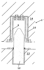
As shown in figures 4, 5 and 6, according to a
second preferred embodiment of the invention, the joining
element 1' comprises two coaxial cylindrical pieces 9 and
10 of different diameter, forming between them a volume 11
in which are housed four angularly equi-spaced bodies 2.
In this preferred embodiment there are four bodies, though
the design could always allow for six. These bodies 2 are
of substantially parallelepiped form arched according to
the curvatures of the cylinders that confine them along
their larger faces, as the breakdown of Figure 6 shows.
With this structure, the innermost piece 9 is
designed to receive a positioning element 12, as shown in
Figure 9, fitted by its lower part into a first lower
module 13 and with the outermost part 10 to be left fitted
into the module immediately above it 14, so that the four
bodies transmit the lateral forces between the pieces and
therefore between the first lower module 13 and the second
immediately higher module 14.
In this second embodiment, the above-mentioned
pieces each include covers 15 and 16 with at least one
CA 02723231 2010-10-28
orifice 17 on one of their ends, such that said
cylindrical pieces can be attached to each other by one or
more fastening screws, as shown in figures 4 and 6.
5 Third preferred embodiment
According to another embodiment, the joining
element 1' ' of the invention is of the type that includes
two bent plates 18 and 19 each provided with at least one
10 orifice, and each one for attachment to as many adjoining
modules 20, 21, with said orifices facing opposite each
other in order to take an attachment screw 22 and a
plurality of washers 23, as shown in Figure 7. More
specifically, this embodiment is characterised in that
said at least one body 2a or 2b is placed between at least
two of said washers 23, placed in such a way that said
body can transmit the horizontal loads between said
adjoining modules 20 and 21, as shown in Figure 8.
In order to be able to transmit forces in the
longitudinal direction of said screw in both directions,
the joining element can include two of said bodies placed
between two pairs of washers, with at least one of them 2a
situated between said two plates, and the other 2b on the
other side of one of the plates in relation to the
preceding one.
Accordingly, in a building formed of prefabricated
elements, the simultaneous use of the three forms of
preferred embodiment of the invention allows a flexible
and predictable structural response to be achieved with
the calculation, such that buildings many storeys high can
be assembled with structural solidity.