Note: Descriptions are shown in the official language in which they were submitted.
CA 02723266 2010-11-01
WO 2009/132778 PCT/EP2009/002808
Medication delivery device
The present invention relates to a medication delivery device, a use of the
device and
a method of manufacturing or assembling the device. The invention refers
particularly
to dosing mechanisms suitable for use in such medication delivery devices, in
particular in pen-type injectors, preferably having a dose setting member and
a drive
device enabling the dose setting and the administration of a medicinal product
from a
multi-dose medication cartridge. In particular, the present invention relates
to such
medication delivery devices where a user may set and dispense a dose of
medication
to be delivered from a multi-dose cartridge. Most preferably, the medication
delivery
device comprises a multi-dose medication cartridge which can be replaced when
the
medication has been fully dispensed.
The present invention further relates to a dosing mechanism for a medication
delivery
r,
device, and particularly to a dosing mechanism comprising a dose setting
limiting
mechanism with a dose limiting member which prevents the setting of a dose of
medication which exceeds a maximum amount of medicament to be dispensed from a
medication receptacle, essentially the total amount of medication contained in
the
medication receptacle of the medication delivery device. Most preferably the
dose
limiting member interacts (e.g. moves into abutment) with a stop element of
the piston
rod of the medication delivery device in order to limit the movement of a dose
setting
member for increasing a set dose of medication to be delivered when a user
tries to
set a dose exceeding the content remaining in the medication receptacle.
Such medication delivery devices have application where regular injections by
persons
without formal medical training occur, i.e., patients. This is increasingly
common
amongst those having diabetes where self-treatment enables such persons to
conduct
effective management of their diabetes.
These circumstances set a number of requirements for medication delivery
devices of
this kind. The device must be robust in construction, yet easy to use in terms
of the
CA 02723266 2010-11-01
WO 2009/132778 PCT/EP2009/002808
2
manipulation of the parts, understanding by a user of its operation and the
delivery of
the required dose of medicament. Dose setting must be easy and unambiguous. In
the
case of those with diabetes, many users will be physically infirm and may also
have
impaired vision requiring the dosing mechanism to have a drive device which
requires
a low dispensing force and the medication delivery device to have an easy to
read
dose setting display.
As a result of environmental and economical reasons this kind of medication
delivery
device has been developed to allow only a part of the device to be discarded
after all
the medicament has been delivered, usually the medication cartridge only. This
provides the additional requirement for such a medication delivery device that
the
resetting of the drive mechanism, when a new cartridge is attached to or
inserted into
the medication delivery device, needs to be easy and unambiguous without the
need
for the user to touch any component of the drive mechanism directly, thereby
reducing
the possibility of damage to the drive mechanism through e.g. contamination.
A further requirement of multi-dose medication delivery devices with means for
setting
variable doses to be delivered is to indicate to a user if he is attempting to
set a dose
of medication having a larger size than what is remaining in the medication
receptacle
(e.g. a medication cartridge). The user should further be prevented from
setting a dose
which exceeds the amount of medication left in the cartridge of the medication
delivery
device to avoid the potentially dangerous situation of the user believing that
the set
dose has been entirely injected, even though this is not the case, because the
set dose
exceeded the amount of medication left in the medication receptacle.
User operated medication delivery devices are well known within the medical
field.
Furthermore some medication delivery devices with special end-of-content
mechanisms are also known in the art.
EP 1250167 131 discloses a limiting mechanism that prevents setting of a dose
that
exceeds the amount of liquid left in a cartridge of an injection device. WO
2006/128794
A2 describes an injection device comprising a track and a track follower which
track
CA 02723266 2010-11-01
WO 2009/132778 PCT/EP2009/002808
3
follower is moved along in the track when setting a dose and engages an end-
wall of
the track when the summarized set doses equal the initial amount of liquid in
the
reservoir thereby preventing a user from setting a dose larger than the
remaining
content of the reservoir. WO 2007/017052 Al is also directed towards a
mechanism
for preventing setting of a dose which exceeds the amount of medicament in a
reservoir in an injection device.
All of these dose setting limiting mechanisms known in the art have the
drawback e.g.
that they do not allow or at least hinder the resetting of the medication
delivery device
after the empty reservoir has been replaced by a full reservoir. For resetting
such a
device the piston rod and the limiting mechanism have to be moveable back into
their
initial positions without having to overcome a large resistance and with the
smallest
possible effort for the user.
The object of the invention is to avoid the disadvantages of known medication
delivery
devices, particularly to provide an alternative dose setting limiting
mechanism, most
preferably an end-of-content mechanism which can be integrated into a flexible
reset
mechanism for use in a medication delivery device by means of which the
medication
delivery device can be reset for re-use when the medication cartridge is
replaced.
Another object of the invention is to provide a dose setting limiting
mechanism which
securely limits the dose setting corresponding to the amount of medicament
left in the
medication receptacle of the medication delivery device, in particular by
locking the
dose setting member with the housing, thereby preventing the further movement
of the
dose setting member in a dose increasing direction with respect to the
housing.
The medication delivery device according to the present invention provides a
valuable
technical alternative for known medication delivery devices. The medication
delivery
device according to the present invention e.g. has the advantage that the dose
setting
limiting mechanism securely and precisely limits the setting of a dose
corresponding to
the maximum amount of medicament to be dispensed from a medication receptacle,
especially by the direct interaction of the dose limiting member with the
piston rod the
CA 02723266 2010-11-01
WO 2009/132778 PCT/EP2009/002808
4
position of which is directly related to the amount of medicament left in the
medication
receptacle. Another advantage of the present invention is that the piston rod
can be
driven back into the device body when a new cartridge is attached, without the
user
having to touch any part of the dosing mechanism in particularly without
touching any
component of the dose setting limiting mechanism, e.g. the dose limiting
member. The
medication delivery device according to instant invention further provides the
advantage of an easy replacement of the medication cartridge almost without
application of pressure on the bung of the cartridge during resetting of the
device and
therefore without pressurization of the medication within the cartridge before
the first
setting and dispensing of a dose.
According to the invention, a medication delivery device is provided,
comprising:
o a medication receptacle,
o a dosing mechanism comprising
o a piston rod which is moveable in a distal direction for medication
delivery
o a drive device for moving the piston rod in the distal direction for
medication delivery,
o a dose setting member for setting a dose of medication to be
delivered and
o a dose limiting member which prevents the setting of a dose of
medication which exceeds an amount of medication contained in the
medication receptacle and
o a housing which houses at least part of the dosing mechanism.
The dose limiting member is designed for axial movement in a proximal
direction with respect to the piston rod during dose setting and the dose
limiting
member comprises a first stop element and the piston rod comprises a second
stop element, the first and second stop elements stopping an axial movement of
the dose limiting member in the proximal direction with respect to the piston
rod
when the first and second stop elements catch, thereby limiting a movement of
the dose setting member for increasing a set dose of medication to be
delivered,
CA 02723266 2010-11-01
WO 2009/132778 PCT/EP2009/002808
wherein the dose limiting member and the piston rod only interact directly,
when
the first and second stop elements catch.
Accordingly, the dose limiting member and the piston rod do not interact
directly during
5 the normal use (dose setting and dose delivery) of the medication delivery
device as
long as the amount of medication within the medication receptacle is
sufficient. Only
when the user attempts to set a dose which exceeds the amount of medication
left in
the medication receptacle, the first and second stop elements of the dose
limiting
member and the piston rod, respectively, catch (e.g. engage or abut),
resulting in a
direct interaction of the dose limiting member and the piston rod. This
interaction of the
piston rod and the dose limiting member only in this one case of the "last
dose
situation" of the device has the advantage, that there is also no interaction
between the
dose limiting member and the piston rod during resetting of the device (i.e.
moving
back the piston rod to its initial position when inserting a new cartridge
into the device).
Therefore, the dose limiting member does not prevent or hinder the resetting
of the
medication delivery device.
According to a preferred embodiment of the present invention the dose limiting
member is engaged with the dose setting member, the dose limiting member
stopping
a dose increasing movement of the dose setting member when the axial movement
of
the dose limiting member is stopped. The direct engagement has the advantage
of the
dose limiting member being able to stop the dose increasing movement of the
dose
setting member directly and not indirectly via other components of the device.
Preferably, the dose limiting member is engaged with the dose setting member
by
means of a thread or splines.
Alternatively and according to another preferred embodiment, the dose limiting
member can e.g. be engaged with an insert of the dose setting member which is
prevented from moving with respect to the dose setting member or which is
provided
for limited movement (i.e. limited axial and/or rotational movement) with
respect to the
dose setting member. Preferably, the dose limiting member is engaged with the
insert
of the dose setting member by means of a thread or splines.
CA 02723266 2010-11-01
WO 2009/132778 PCT/EP2009/002808
6
According to a preferred embodiment of the present invention the dose limiting
member is coupled to or engaged with the dose setting member
= so that the dose limiting member is moved in the proximal direction with
respect to the housing and with respect to the piston rod during dose setting
when the set dose of medication to be delivered is increased and
= so that the dose limiting member is moved in the distal direction with
respect
to the housing during medication delivery.
The dose limiting member can e.g. be engaged with the dose setting member via
an
internal thread of the dose setting member or engaged with a threaded insert
of the
dose setting member.
Preferably, the dose setting member is a dose dial sleeve which is threadedly
engaged
..,;+h the hni icinn and therefore rotates and moves proximally with respect
to the
1%! with uw .,v.wv...y .....
housing during setting of a higher dose, rotates and moves distally with
respect to the
housing during reducing the set dose and rotates and moves distally with
respect to
the housing during dose delivery.
The dose limiting member is preferably threadedly engaged with the dose
setting
member or with an insert of the dose setting member, it most preferably
comprises an
essentially tubular sleeve which is threadedly engaged with the dose setting
member
or with an insert of the dose setting member.
Preferably, the dose limiting member comprises an opening, wherein the piston
rod
extends through the opening and the first stop element is provided as a
surface
surrounding the opening. Most preferably, the dose limiting member comprises
an
internal flange which has an opening, wherein the piston rod extends through
the
opening and wherein the internal flange comprises the first stop element. The
first stop
element is preferably an abutment surface of the internal flange of the dose
limiting
member. As long as the first stop element does not catch the second stop
element of
the piston rod, a relative axial movement of the piston rod (within/through
the opening
CA 02723266 2010-11-01
WO 2009/132778 PCT/EP2009/002808
7
of the flange) and the dose limiting member is allowed without interaction of
the piston
rod and the dose limiting member.
In some embodiments of the present invention the first stop element can
comprise a
set of teeth or an abutment surface on a flange.
In some embodiments the second stop element is a protrusion which extends
radially
from the piston rod, the axial position of the protrusion on the piston rod
being related
to the total amount of medicament to be dispensed from the medication
receptacle.
The protrusion may e.g. be an outer rim or lug. It is preferably designed such
that it
catches an abutment surface (e.g. of an internal flange) of the dose limiting
member
when a setting of a dose is attempted which exceeds the amount of medication
contained in the medication receptacle, thereby stopping an axial movement of
the
dose limiting member in the proximal direction with respect to the piston rod.
According to a particularly advantageous embodiment of the invention the
second stop
element is the end of a thread on the piston rod. Preferably, the piston rod
comprises
two threaded regions, a first threaded region which does not influence axial
movement
of the dose limiting member and a second threaded region, wherein one end of a
thread in the second threaded region forms the second stop element. In this
embodiment the cross section of the second thread is preferably larger than
the cross
section of the first thread, the first thread passing through an opening of
the dose
limiting member without interaction of the piston rod with the dose limiting
member and
the second thread not passing through the opening but abutting the surrounding
edge
of the opening. Most preferably, the piston rod comprises two threaded
regions, the
two threaded regions having threads which are oppositely disposed.
According to a preferred embodiment of the present invention the dose limiting
member is allowed to move axially and is prevented from rotation with respect
to the
housing. Preferably, the dose limiting member is splined to the housing and is
thereby
prevented from rotation with respect to the housing. Preferably, the dose
limiting
CA 02723266 2010-11-01
WO 2009/132778 PCT/EP2009/002808
8
member is non-rotatable with respect to the housing and piston rod rotates
during dose
delivery with respect to the housing and with respect to the dose limiting
member.
Preferably, the dose limiting member is positioned in the same position with
respect to
the housing prior to dose setting and after dose delivery, most preferably
moving
axially in one direction during the setting of a higher dose and in the other
direction
during the setting of a lower dose and/or during dose delivery. Preferably the
distance
of axial travelling of the dose limiting member in one direction with respect
to the
housing from an initial position to the set dose position during dose setting
and the
distance of axial travelling of the dose limiting member in the other
direction with
respect to the housing from the set dose position to the initial position
during dose
delivery are essentially the same. According to a particularly advantageous
embodiment of the invention, the dose limiting member and the piston rod
travel
essentially the same distance in the distal direction during medication
delivery.
In some embodiments the medication delivery device according to the present
invention further comprises a drive device which is engaged with the piston
rod and
releasably engaged with the dose setting member. Preferably, the piston rod
comprises two threaded regions, the two threaded regions having threads which
are
oppositely disposed, wherein a second threaded region is provided for threaded
engagement with the drive device, preferably a drive sleeve. The first
threaded region
can e.g. be provided for threaded engagement with a nut means which is non-
rotatably
attached with or integral of the housing. The releasable engagement between
the drive
device and the dose setting member (e.g. a drive sleeve and a dose dial
sleeve) can
e.g. be achieved by means of a clutch mechanism.
In some embodiments the medication delivery device according to the present
invention further comprises a clutch means located between the dose setting
member
and the drive device (preferably between the dose dial sleeve and the drive
sleeve)
which is provided to releasably couple the drive device with the dose setting
member,
wherein when the dose setting member and the drive device are coupled, both
are
allowed to rotate with respect to the housing and when the dose setting member
and
CA 02723266 2010-11-01
WO 2009/132778 PCT/EP2009/002808
9
the drive device are decoupled, rotation of the dose setting member with
respect to the
housing is allowed, whilst rotation of the drive device with respect to the
housing is not
allowed and axial movement of the drive device is allowed so that a force is
transferred
to the piston rod in the distal direction. When the dose setting member and
the drive
device are decoupled, rotation of the drive device with respect to the housing
can e.g.
be prevented by the drive device engaging another component of the medication
delivery device which is non-rotateable with respect to the housing.
The medication delivery device according to the present invention can e.g. be
designed such that the dose limiting member comprises a tubular part which
surrounds
the piston rod, the drive sleeve and the clutch means and which is surrounded
by a
dose dial sleeve.
According to a preferred embodiment of the present invention, the dosing
mechanism
comprises at least one locking member for locking the dose setting member with
the
housing, thereby preventing further rotation of the dose setting member with
respect to
the housing in a dose increasing direction, the locking member being activated
when
the first stop element of the dose limiting member catches the second stop
element of
the piston rod and when a force (e.g. a torque) is exerted on the dose setting
member
in the dose increasing direction. The catching of the two stop elements
results in
stopping the axial movement of the dose limiting member in the proximal
direction and
thus the dose limiting member stopping the dose increasing movement of the
dose
setting member. Any further force/torque exerted by the user on the dose
setting
member is transferred to the at least one locking member and moves the at
least one
locking member into a locking position in which it locks the dose setting
member with
the housing. This locking action is an additional feature to prevent a further
dose
increasing movement of the dose setting member (the dose setting member being
stopped by the dose limiting member and by the locking member).
Preferably the locking member interacts directly with or is connected to (i.e.
attached to,
engaged with or an integral part of) an insert (preferably a threaded insert)
of the dose
setting member, which insert is in engagement (preferably in threaded
engagement)
CA 02723266 2010-11-01
WO 2009/132778 PCT/EP2009/002808
with the dose limiting member and designed for (preferably limited) movement
(i.e.
axial movement and/or rotational movement) with respect to the dose setting
member.
This means that the insert and the dose setting member are moveable with
respect to
each other, but are preferably held in a certain position with respect to each
other (e.g.
5 by a biasing means) before the first and second stop elements catch. When
the two
stop elements abut (thereby preventing a further axial movement of the dose
limiting
member in the proximal direction), a further force/torque exerted by the user
on the
dose setting member in the dose increasing direction is preferably transmitted
to the
insert, thereby moving the insert so that it activates the locking member. The
dose
10 setting member can e.g. be allowed to perform a movement (preferably only a
small
movement) in a dose increasing direction with respect to the insert when the
first and
second stop elements abut, thereby moving the at least one locking member and
at
least one locking feature of the housing into engagement.
The medication delivery device may e.g. comprise at least one locking member
which
IJ I II IIIGU wuuv. ...... ~
interacts directly with or is connected to (i.e. attached to, engaged with or
an integral
part of) the dose setting member. The locking member(s) can e.g. be separate
parts
which are each connected to the dose setting member via a swivel axis.
Preferably, the at least one locking member or at least one locking feature of
the
housing is held in a first deactivated position by a biasing means. In some .
embodiments the at least one locking member is swivelled out by means of at
least
one ramp feature when activated, thereby engaging at least one locking feature
of the
housing. For example, an insert of the dose setting member comprises the at
least one
ramp feature and the at least one locking member is connected to the dose
setting
member via a swivel axis. The dose setting member has at least one opening
adjacent
to the at least one locking member through which the at least one locking
member and
the at least one ramp feature of the insert can interact. The dose setting
member
performs a rotational movement in a dose increasing direction with respect to
the insert
when the end-of content mechanism is activated (e.g. when the first and second
stop
elements abut, the dose limiting member stopping a further movement of the
insert)
and the user exerts a further force/torque on the dose setting member in the
dose
CA 02723266 2010-11-01
WO 2009/132778 PCT/EP2009/002808
11
increasing direction, thereby moving the dose setting member with respect to
the insert
and thus the at least one locking member (preferably against the force of a
biasing
means) over the at least one ramp feature of the insert, the locking member
thereby
swivelling out and engaging at least one locking feature of the housing. The
at least
one locking member is moved into engagement with the locking feature by the
ramp
feature preferably because the ramp feature slides along a protrusion of the
locking
member (which can e.g. also be ramp-shaped).
The locking member is preferably automatically (e.g. by the force of a biasing
means)
disengaged from the locking feature of the housing as soon as the set dose is
reduced
and/or the user no longer exerts a force/torque on the dose setting member in
the dose
increasing direction (e.g. when the set dose is dispensed). Preferably a
biasing means
is provided which holds the locking member in its (de-activated) initial
position as long
as the end-of-content mechanism is not activated. Most preferably the biasing
means
4r_ thereby also prevents the insert from being moved (e.g. rotated) with
respect to the
dose setting member (and vice versa) as long as the end-of-content mechanism
is not
activated, e.g. by pressing a locking member against the ascending slope of a
ramp
feature of the insert.
The locking members can, alternatively, be integral parts of an insert of the
dose
setting member, the locking members extending (radially) through openings in
the
dose setting member. The locking members can for example be made of a flexible
material, e.g. a flexible polymeric material. The dose setting member performs
a
rotational movement in the dose increasing direction with respect to the
insert when
the end-of content mechanism is activated (e.g. when the first and second stop
elements abut) and the user exerts a force on the dose setting member in the
dose
increasing direction, thereby moving the locking members against an edge of
the
openings, the locking members thereby swivelling out and engaging locking
features of
the housing.
According to a preferred embodiment of the present invention the at least one
locking
member is engaged with grooves or splines in the housing when the locking
member is
CA 02723266 2010-11-01
WO 2009/132778 PCT/EP2009/002808
12
activated, thereby preventing rotation of the dose setting member with respect
to the
housing in the dose increasing direction.
According to one embodiment the at least one locking member is a hook which is
hooked into a hooking feature of the housing when the locking member is
activated,
thereby preventing rotation of the dose setting member with respect to the
housing in
the dose increasing direction.
In some embodiments the locking member comprises at least one tooth,
preferably a
plurality of teeth, for engaging a locking feature of the housing, e.g. a
component with
a tooth, preferably with a plurality of teeth. The locking member is connected
to (i.e.
attached to, engaged with or an integral part of) or interacts directly with
the dose
setting member. The locking feature is connected to (i.e. attached to, engaged
with or
an integral part of) or interacts directly with the housing or with an insert
of the housing
such that a movement (i.e. a rotational and/or axial movement, preferably a
rotational
movement) of the locking feature with respect to the housing in a dose
increasing
direction is prevented. Therefore, a movement (i.e. a rotational and/or axial
movement,
preferably a rotational movement) of the locking member in the dose increasing
direction with respect to the housing is prevented when the locking member and
the
locking feature are engaged, e.g. when the teeth of the locking member and the
teeth
of the dose limiting member are engaged, thereby preventing a further movement
(i.e.
a rotational and/or axial movement, preferably a rotational movement) of the
dose
setting member with respect to the housing in a dose increasing direction.
In this embodiment a biasing means is preferably located between the locking
member
and the locking feature for keeping the locking member and the locking feature
disengaged, preferably the teeth of the locking member and the teeth of the
locking
feature disengaged, until the locking member is activated (e.g. when the first
stop
element of the dose limiting member abuts the second stop element of the
piston rod
and when a further force or torque is exerted on the dose setting member in
the dose
increasing direction).
CA 02723266 2010-11-01
WO 2009/132778 PCT/EP2009/002808
13
According to a preferred embodiment of the present invention the locking
member is a
first toothed ring connected to a dose dial sleeve and the locking feature is
a second
toothed ring, the second toothed ring being prevented from rotation with
respect to the
housing, thereby preventing rotation of the dose dial sleeve with respect to
the housing
when the two toothed rings are engaged.
The dose dial sleeve preferably has a threaded insert which is engaged with
the dose
limiting member, the second toothed ring being prevented from moving axially
with
respect to the threaded insert and the threaded insert being provided for
axial
movement with respect to the dose dial sleeve when the first and second stop
members catch and a further force is exerted on the dose dial sleeve in a dose
increasing direction, the first and second toothed rings thereby being moved
into
engagement.
,-cording to a preferred embodiment of the present invention the dose delivery
device
r
further comprises a cartridge which contains the medication, the cartridge
comprising a
piston which is moved in a distal direction by the piston rod for medication
delivery,
wherein the dose limiting member and/or the at least one locking member is
provided
to prevent setting of a dose of medication which exceeds a maximum amount of
medication to be dispensed from the cartridge.
The present invention further refers to a medication delivery device
comprising
o a medication receptacle (e.g. a cartridge filled with a liquid medication),
o a dosing mechanism comprising
o a dose setting member for setting a dose of medication to be
delivered and
o a dose setting limiting mechanism (end-of-content mechanism) which
prevents the setting of a dose of medication which exceeds a
maximum amount of medication to be delivered from the medication
receptacle and
o a housing which houses at least part of the dosing mechanism,
CA 02723266 2010-11-01
WO 2009/132778 PCT/EP2009/002808
14
wherein the dose setting limiting mechanism comprises at least one locking
member
for locking the dose setting member with the housing, thereby preventing
movement of
the dose setting member with respect to the housing in a dose increasing
direction.
The at least one locking member of this variant of the present invention can
be
activated e.g. when two components (for example two stop elements as described
above or a track follower and an end wall) of the medication delivery device
are moved
into abutment or engagement during dose setting and when the user then exerts
a
further force on the dose setting member to move it further in the dose
increasing
direction. This force is preferably transferred to the locking member in order
to be
activated and to be brought into a locking state in which the locking member
locks the
dose setting member with the housing of the dose delivery device, thereby
preventing
movement (preferably preventing rotation) of the dose setting member with
respect to
the housing in the dose increasing direction.
In the locking state the at least one locking member can e.g. be radially
engaged with
the surrounding housing of the medication delivery device (preferably with a
locking
feature of the housing) or with another component of the device which is not
allowed to
move in the dose increasing direction with respect to the housing.
Alternatively the at
least one locking member can in a locking state be prevented from moving in a
dose
increasing direction (e.g. not allowed to rotate) with respect to the housing
e.g. when
the locking member is axially engaged with a locking feature of the housing,
the
locking member preferably being
= engaged with the dose setting member directly or
= an integral part of the dose setting member or
= engaged with another component which is engaged with the dose setting
member.
The at least one locking member according to this embodiment of the present
invention is preferably designed similarly to the locking members described
above.
The locking feature of the housing can e.g. be
CA 02723266 2010-11-01
WO 2009/132778 PCT/EP2009/002808
= engaged with the housing directly or
= an integral part of the housing or
= engaged with another component which is engaged with the housing.
According to one preferred embodiment, the locking feature of the housing is
further
5 engaged with a moveable insert of the dose setting member, the locking
feature being
prevented from moving axially with respect to the insert.
The term "medication delivery device" according to instant invention shall
mean a
single-dose or multi-dose, disposable or re-useable device designed to
dispense a
10 dose of a medicinal product, preferably multiple selected doses, e.g. of
insulin, growth
hormones, low molecular weight heparins, and their analogues and/or
derivatives etc.
Said device may be of any shape, e.g. compact or pen-type. Dose delivery may
be
provided through a mechanical (optionally manual) dosing mechanism or
electrical
dosing mechanism or electro-mechanical dosing mechanism or stored energy
dosing
15 mechanism, such as a sprin^ etr nose selection may be provided through a
manual
mechanism or electronic mechanism or electro-mechanical mechanism.
Additionally,
said device may contain components designed to monitor physiological
properties
such as blood glucose levels, etc. Furthermore, the said device may comprise a
needle or may be needle-free. Preferably, the term "medication delivery
device" shall
mean a re-useable multi-dose pen-type device having mechanical and manual dose
selection and dose delivery mechanisms, which is designed for regular use by
persons
without formal medical training such as patients. Preferably, the medication
delivery
device is of the injector-type. Most preferably the medication delivery device
is
designed to deliver a fluid medication.
The term "dose setting limiting mechanism" or "end-of-content mechanism"
according
to the present invention shall preferably mean any component and/or components
and/or assembly designed to prevent the setting of a dose which exceeds a
maximum
amount of medication to be dispensed from the medication receptacle of the
medication delivery device. Most preferably the term "dose setting limiting
mechanism"
or "end-of-content mechanism" according to the present invention shall
preferably
mean any component and/or components and/or assembly designed to prevent the
CA 02723266 2010-11-01
WO 2009/132778 PCT/EP2009/002808
16
setting of a dose which exceeds the amount of medication left in the
medication
receptacle at the time when the dose is set.
The term "medication receptacle" in the context of the present invention shall
preferably mean a cartridge containing a medication or a cartridge assembly,
most
preferably a cartridge holder for receiving a cartridge containing a
medication.
Furthermore, the terms "medication receptacle" and "cartridge" and "cartridge
assembly" are exchangeable in the context of the present invention. This means
that
by using the term "medication receptacle", any meaning of the terms
"cartridge" or
"cartridge assembly" is included, and vice versa.
The term "cartridge holder" according to instant invention shall mean any
component
and/or components designed to house a medicament cartridge containing a
medication to be delivered by the medication delivery device. Said cartridge
holder
may be of any shape, e.g. cylindrical and/or tubular. In general, the
cartridge holder
may be unitary or a multipart component of a cylindrical tubular or non-
tubular shape. It
may be made of any suitable material known by a person skilled in the art,
e.g. of a
transparent material. Further the cartridge holder or an insert of the
cartridge holder is
preferably provided with engagement means, e.g. helical threads or part
threads or
bayonet or the like, on an external and/or internal surface of the distal end
and/or
proximal end of the cartridge holder or the insert designed for engagement
with
corresponding engagement means located on an exterior and/or interior surface
of a
housing, an insert of the housing and/or a needle assembly. In a preferred
embodiment the cartridge holder is of a unitary tubular design having an
external
thread located at its proximal end.
The term "housing" according to instant invention shall preferably mean any
exterior
housing ("housing", "body", "shell") or interior housing ("insert", "inner
body") having an
engaging means, such as a helical thread, spline or any other suitable means
known
by a person skilled in the art. The housing may be designed to enable the
safe, correct,
and comfortable handling of the medication delivery device or any of its
mechanisms.
Usually, it is designed to engage with any of the inner components of the
medication
CA 02723266 2010-11-01
WO 2009/132778 PCT/EP2009/002808
17
delivery device (e.g., a dosing mechanism, cartridge, plunger, piston rod),
house, fix,
guide, and/or protect by limiting the exposure to contaminants, such as
liquid, dust, dirt
etc. In general, the housing may be unitary or a multipart component of
tubular or non-
tubular shape. The exterior housing may also serve to house a cartridge from
which a
number of doses of a medicinal product may be dispensed.
The terms "stop element" or "stop means" according to instant invention shall
mean
any feature(s) and/or component(s) of the medication delivery device designed
to
prevent axial and/or rotational movement of any component and/or components at
least in one direction. In a preferred embodiment of instant invention, the
term "stop
element" shall mean any feature perpendicular to the distal-proximal axis of
the
medication delivery device (particularly any planar surface feature
perpendicular to the
distal-proximal axis of the medication delivery device) designed to prevent
axial
movement of a component in one direction when this component abuts the
perpendicular feature. According to another preferred embodiment of the
present
ra=r-
invention the term "stop element" shall mean any feature which provides a
radial or
rotational stop designed to prevent rotational movement of a component in one
rotational direction when an abutment element of the component abuts the
radial or
rotational stop feature.
The term "dose limiting member" according to the present invention shall
preferably
mean a component ("end stop") of the dosing mechanism which prevents the
setting of
a dose which exceeds the amount of medication left in the medication
receptacle.
Preferably the dose limiting member is a component which is secured against
rotation
but allowed to move axially with respect to a housing and which shall prevent
at least
one component of the dosing mechanism from rotational and/or axial movement
when
a final dose has been set, thereby preventing the setting of a dose which
exceeds the
amount of medication left in the cartridge. Furthermore, the "dose limiting
member"
shall preferably have a helical thread on an exterior surface designed to
engage with
an interior helical thread of a dose dial sleeve of the dosing mechanism or of
an insert
of a dose dial sleeve of the dosing mechanism. Preferably the lead of an
external
helical thread of the said dose dial sleeve for threaded engagement with the
housing
CA 02723266 2010-11-01
WO 2009/132778 PCT/EP2009/002808
18
shall be greater than the lead of the internal helical thread of the dose dial
sleeve for
threaded engagement of the said dose limiting member.
The term "engaging" according to instant invention shall mean the interlocking
of two
or more components of the dosing mechanism/medication delivery device, by
means
of e.g. a spline, thread, or meshed teeth connection, preferably the
interlocking of
threads of components ("threadedly engaged").
The term "engagement means" according to the present invention shall
preferably
mean any means known to those skilled in the art which can be used to engage
two or
more components of a medication delivery device, e.g. full or part threads,
grooves,
engaging elements which mesh with threads and/or grooves or means which form a
bayonet lock.
The term "disengaging" according to instant invention shall mean the unlocking
of two or more components of the dosing mechanism/medication delivery device.
According
to one example the term "disengaging" according to instant invention shall
mean the
unlocking of two or more components of the dosing mechanism/medication
delivery
device under the force of a biasing means. Two components can also be
disengaged
by the force of a user of the device, e.g. by a patient unscrewing the
medication
receptacle from the housing.
The terms "to interact directly" or "direct interaction" according to the
present invention
shall mean any direct interaction of two components of the medication delivery
device
which leads to a load/force transmission from one of the components to the
other. The
term "to interact directly" particularly comprises interactions of two
components like
one component driving a movement (axial movement and/or rotation) of the other
component or like one component stopping or preventing a movement (axial
movement and/or rotation) of the other component. Such a direct interaction
requires
an engagement or at least an abutment of the two components. However, if one
component only moves along another component this mere contact between the two
CA 02723266 2010-11-01
WO 2009/132778 PCT/EP2009/002808
19
components is not interpreted as causing a direct interaction between the two
components in the context of the present invention.
The term "biasing means" according to instant invention shall preferably mean
any
component that is provided for exerting a force on a component and/or
components to
ensure that the component and/or components are forced together (e.g. into
engagement) or forced apart (e.g. out of engagement). Preferably the biasing
means
may be manufactured from any suitable flexible energy storage material known
by a
person skilled in the art (e.g. metal, rubber or plastics) and may take any
suitable form,
e.g., a spring.
The term "distal end" according to instant invention shall mean the end of the
device or
a component of the device which is closest to the dispensing end of the
device.
Preferably a needle assembly is provided at the distal end of the medication
delivery
device of +he mcant invention the needle of which can be inserted into the
skin of a
I J ucvwc of a 1... r., es.,.... .. _
patient for medication delivery. The distal direction is therefore the
direction from the
proximal towards the distal end.
The term "proximal end" according to instant invention shall mean the end of
the
device or a component of the device which is furthest away from the dispensing
end of
the device. Preferably a button is provided at the proximal end of the
medication
delivery device of the present invention which is pushed for dose delivery.
The
proximal direction is therefore the direction from the distal towards the
proximal end.
The term "dose increasing direction" according to the present invention shall
preferably
mean a direction of movement of the dose setting member with respect to the
housing
when the set dose is increased. This movement may be an axial and/or a
rotational
movement of the dose setting member. Preferably the movement is an axial
movement
in the proximal direction, most preferably an axial movement in the proximal
direction
in combination with a rotational movement in one rotational direction
(clockwise or
counterclockwise). In the latter case the movement of the dose setting member
in the
dose increasing direction can be limited by stopping the movement in the
proximal
CA 02723266 2010-11-01
WO 2009/132778 PCT/EP2009/002808
direction and/or by stopping the movement in the rotational direction. A force
which is
exerted by a user on the dose setting member in the dose increasing direction
can e.g.
be a torque exerted on the dose setting member with respect to the housing if
the dose
is increased by winding the dose setting member out of the housing.
5
The term "dosing mechanism" according to instant invention shall mean any
component and/or components and/or assembly designed to allow a user to select
and/or set a dose to be dispensed and/or to provide and/or to transmit a force
necessary to dispense a dose of a medication. Said dosing mechanism may be
10 composed of mechanical and/or electro-mechanical and/or electronic
components.
Additionally, the dosing mechanism may be housed by and/or engaged with the
device
housing or may be an independent assembly. The dosing mechanism of instant
invention preferably comprises a piston rod and a drive device for moving the
piston
rod in the distal direction for medication delivery. Preferably, the dosing
mechanism of
15 instant invention comprises a drive sleeve and a dose dial sleeve. More
preferably, the
dosing mechanism of instant invention comprises a drive sleeve, a dose dial
sleeve, a
clutch means, a dose dial grip and a button means.
The term "piston rod" according to instant invention shall mean a component
adapted
20 to operate through/within the housing, designed to transmit axial movement
(preferably
towards the distal end) through/within the medication delivery device,
preferably from a
drive sleeve to the piston of the cartridge, for the purpose of
discharging/dispensing a
medication from the cartridge, preferably an injectable product. Said piston
rod may be
flexible or not. It may be a simple rod, a lead-screw, a part of a rack and
pinion system,
a part of a worm gear system, or the like. The "piston rod" shall further mean
a
component having a circular or non-circular cross-section. It may be made of
any
suitable material known by a person skilled in the art.
In a preferred embodiment, the piston rod comprises at least two, more
preferably two,
external and/or internal helical threads (threaded sections). In another
preferred
embodiment of the piston rod according to instant invention, a first helical
thread (first
threaded section) is located at a distal end and a second helical thread
(second
CA 02723266 2010-11-01
WO 2009/132778 PCT/EP2009/002808
21
threaded section) is located at a proximal end of the said piston rod, whereby
the said
threads of the threaded sections have opposite dispositions. In another
preferred
embodiment the piston rod of instant invention comprises at least two threaded
sections with threads having the same leads and the same pitches at the distal
and the
proximal end. In yet another preferred embodiment of instant invention the
lead and
the pitch of the second helical thread of the piston rod shall be greater than
the lead
and the pitch of the first helical thread. More preferred, the ratio of the
leads of the
helical threads of the said first and the second helical threads is in the
range of 1:1,01
to 1:20, even more preferred in the range of 1:1,1 to 1:10, most preferred
1:2,3.
Preferably, one of the said threads (the thread of the second threaded
section) is
designed to engage with the drive sleeve. Preferably another of the said
threads (the
thread of the first threaded section) is designed to engage with a reset
element, more
preferably with a nut means. According- to a most preferred embodiment of the
present
invention, a first external threaded section of the piston rod with a thread
having a
smaller lead is designed to engage with an internal thread of a nut means and
a
second external threaded section of the piston rod with a thread having a
larger lead is
designed to engage with an internal thread of a drive sleeve. In a further
preferred
embodiment of instant invention, the piston rod is provided with a stop
element
designed to limit the proximal axial movement of a dose limiting member. The
stop
element may e.g. be the start of one of the external threads of the piston
rod.
The terms "dose setting member" and "dose dial sleeve" according to instant
invention
shall preferably mean a component of the medication delivery device which is
directly
or indirectly used to select/dial a dose of medication to be delivered.
Additionally or
alternatively the dose setting member or dose dial sleeve is designed to
indicate a
selected dose of a dispensable product (medication). This may be achieved by
use of
markings, symbols, numerals, etc., e.g. printed on the external surface of a
sleeve or
an odometer, or the like. Most preferably the dose setting member or dose dial
sleeve
is marked by means of laser printing. In a preferred embodiment of the present
invention, the dose setting member, in particular the dose dial sleeve is an
essentially
tubular component of essentially circular cross-section having either:
both an internal and external thread, or
CA 02723266 2010-11-01
WO 2009/132778 PCT/EP2009/002808
22
= an internal thread, or
= an external thread.
Preferably, the dose setting member, in particular the dose dial sleeve
comprises an
external thread for engaging an internal thread of the housing or of an insert
of the
housing. Preferably, the dose setting member, in particular the dose dial
sleeve
according to instant invention comprises an external helical thread having a
lead,
which is similar to, preferably the same as the lead of an internal helical
thread of the
drive sleeve. In a more specific embodiment of instant invention, the dose
setting
member or dose dial sleeve is provided with a plurality of radially extending
stop
members adapted to abut a corresponding plurality of radial stops provided
within the
housing or an insert of the housing. These radial stops are preferably
provided for
stopping a further winding of the dose setting member or dose dial sleeve out
of the
housing when a dose is set and/or for stopping the further winding of the dose
setting
member or dose dial sleeve into the housing when a dose has been dispensed.
IJ
The term "drive device" according to the present invention shall preferably
mean any
component and/or components and/or assembly designed to transmit a force to
the
piston rod for dispensing a dose of a medication. Said drive device may be
composed
of mechanical and/or electro-mechanical and/or electronic components. The
drive
device may be housed by and/or engaged with the housing or may be an
independent
assembly. Preferably, the drive device of instant invention comprises a drive
sleeve.
More preferably, the drive device of instant invention comprises a drive
sleeve, a clutch
means and a button means.
The term "drive sleeve" according to instant invention shall preferably mean
any
component for directly or indirectly driving the piston rod in a distal
direction for
medication delivery, most preferably for driving the piston rod directly.
According to a
preferred embodiment of the present invention, the drive sleeve is an
essentially
tubular component of essentially circular cross-section. In a preferred
embodiment the
drive sleeve is engaged with the piston rod. Preferably the drive sleeve
comprises an
internal thread for engaging an external thread of the piston rod. The drive
sleeve is
CA 02723266 2010-11-01
WO 2009/132778 PCT/EP2009/002808
23
further preferably releasably coupled to a dose dial sleeve, most preferably
by a clutch
means.
The term "locking member" according to the present invention shall preferably
mean
any component(s) integral of, engaged with or connected to the dose setting
member
(or an insert of the dose setting member) which can be brought from a first
deactivated
state into a second activated state in which it is (they are) engaged with a
locking
feature of the housing or a locking feature of any component integral of,
engaged with
or connected to the housing. The locking member can e.g. be activated by being
moved from a first into a second position in which it engages the locking
feature or vice
versa by the locking feature being moved from a first into a second position
in which it
engages the locking member. In this activated state the locking member
indirectly or
preferably directly locks the dose setting member with the housing, thereby
preventing
a dose increasing movement (preferably a dose increasing rotation) of the dose
setting
1 member With respect to the housing. Preferably the locking member is a
component
(e.g. a finger or hook) which is rotatable about an axis from the first
deactivated state
into the second activated state and vice versa. Alternatively the locking
member can
e.g. be a component integral of, engaged with or connected to the dose setting
member (or an insert of the dose setting member) which has at least one tooth,
preferably a plurality of teeth, and which can be engaged by a locking feature
of the
housing (preferably a ring having at least one tooth or tooth-shaped recess,
preferably
a plurality of teeth) which is axially moveable from a first position
(deactivated state)
into a second position (activated state) with respect to the dose setting
member and
vice versa.
The term "locking feature" according to the present invention shall preferably
mean any
component(s) integral of, engaged with or connected to the housing which is
prevented
from moving in a dose increasing direction with respect to the housing and
which can
be engaged by a locking member which is integral of, engaged with or connected
to
the dose setting member (or an insert of the dose setting member), thereby
preventing
a dose increasing movement (preferably a dose increasing rotation) of the dose
setting
member with respect to the housing. Preferably the locking feature is at least
one
CA 02723266 2010-11-01
WO 2009/132778 PCT/EP2009/002808
24
protrusion, groove, spline, hook, tooth or the like on the inner surface of
the housing or
on the inner surface of an insert of the housing.
The term "thread" or "helical thread" according to instant invention shall
preferably
mean a full or part thread, e.g., a cylindrical spiral rib/groove, located on
the internal
and/or external surface of a component of the medication delivery device,
having an
essentially triangular or square or rounded section designed to allow
continuous free
rotational and axial movement between components. Optionally, a thread may be
further designed to prevent rotational or axial movement of certain components
in one
direction by being non-overhaulable.
The term "lead" according to instant invention shall preferably mean the axial
distance
a nut would advance in one complete revolution; preferably "lead" shall mean
the axial
distance through which a component having a helical thread, i.e. dose dial
sleeve,
drive sleeves piston rod fi, etc., of the dosing mechanism travels during one
rotation.
drive .7iccv~., ~I.SØ.. g
Therefore the lead is a function of the pitch of the thread of the relevant
component.
The term "pitch" according to instant invention shall preferably mean the
distance
between consecutive contours on a helical thread, measured parallel to the
axis of the
helical thread.
One aspect of the present invention provides a medication delivery device
according to
instant invention for dispensing a medicinal product preferably for dispensing
a
pharmaceutical formulation (e.g. solution, suspension etc.) comprising an
active
compound selected from the group consisting of insulin, growth hormone, low
molecular weight heparin, their analogues and their derivatives.
The medication delivery device according to the present invention can be a pen-
type
device and/or an injector-type device. The medication delivery device can
comprise a
needle or be a needle-free device.
CA 02723266 2010-11-01
WO 2009/132778 PCT/EP2009/002808
The invention further refers to a method of manufacturing or assembling a
medication
delivery device according to one of the above-mentioned embodiments. This
method
preferably comprises the step of providing a dose limiting member as described
above
which is installed within a dosing mechanism.
5
According to the invention, the use of a medication delivery device according
to one of
the above-mentioned embodiments of a medication delivery device for dispensing
a
medicinal product is also provided. The use preferably comprises the
dispensing of a
pharmaceutical formulation (e.g. a liquid medication like a solution, a
suspension etc.)
10 comprising an active compound selected from the group consisting of
insulin, growth
hormone, low molecular weight heparin, their analogues, and their derivatives.
Without any limitation, the present invention will be explained in greater
detail below
with reference to the drawings in which:
= figures 1a to 1c show a cross-sectional view of one embodiment of a
medication
delivery device according to the invention in three different states;
= figures 1d and le show the medication delivery device according to figures
1a to
1c in a state in which the dose limiting member and the piston rod interact in
order to prevent the setting of a higher dose.
figures 2a and 2b show schematically a cut-out of a medication delivery device
according to the present invention comprising at least one locking member.
= figure 3 shows a cut-out of cross-section of another embodiment of a
medication
delivery device according to the present invention comprising a locking
member.
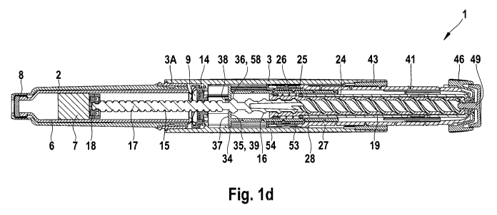
Referring first to Figures 1a to 1c, there is shown a medication delivery
device in
accordance with the present invention in three different positions.
CA 02723266 2010-11-01
WO 2009/132778 PCT/EP2009/002808
26
The medication delivery device 1 comprises a cartridge holder 2 and a
(exterior)
housing 3. Preferably the housing 3 is lacquered. The distal end of the
housing 3 is
provided with an insert 3A which is immovably attached to the housing. The
insert 3A
is provided with second engagement means 4 for engaging first engagement means
5
of the cartridge holder 2. The proximal end of the cartridge holder 2 is
provided with
first engagement means 5 for engaging the second engagement means 4 of the
insert
3A.
A cartridge 6 filled with medication from which a number of doses of the
medication
may be dispensed is provided in the cartridge holder 2. A piston 7 is retained
in the
cartridge 6.
A removable cap (not shown) can be releasably retained over the distal end of
the
cartridge holder 2. Preferably the cap comprises a clip which is snapped onto
the cap.
The cyan can also be lacquered.
The distal end of the cartridge holder 2 is provided with suitable engaging
means 8,
such as a helical thread, bayonet or the like, for engagement with a suitable
needle
assembly (not shown) to enable medicament to be dispensed from the cartridge 6
and
injected.
The medication delivery device 1 according to figures la to le comprises a
dosing
mechanism which includes a piston rod 17 which is moveable in the distal
direction for
medication delivery. The piston rod 17 is of generally circular cross-section.
A pressure
foot 18 is located at the distal end of the piston rod 17. The pressure foot
18 is
preferably made of two separate parts which are snapped together around a
distal end
portion of the piston rod 17. The pressure foot 18 is disposed to abut the
proximal face
of the piston 7 within the cartridge 6. The piston rod 17 is moveable in a
distal direction
by means of a drive device, thereby pushing the piston 7 to move axially
within the
cartridge 6 in the distal direction for medication delivery. A first thread 15
is formed at
the distal end of the piston rod 17 (first threaded section 15). A second
thread 16 is
formed at the proximal end of the piston rod 17 (second threaded section 16).
The first
CA 02723266 2010-11-01
WO 2009/132778 PCT/EP2009/002808
27
thread 15 and the second thread 16 are oppositely disposed. Preferably at
least one of
the first and second threads 15, 16 is a multi-start thread, most preferably
both are
two-start threads.
The drive device comprises a drive sleeve 19 which extends about the piston
rod 17.
The drive sleeve 19 is generally cylindrical. The drive sleeve 19 is provided
at a distal
end with a radially extending flange 20. A helical groove (thread) 21 extends
along the
internal surface of the drive sleeve 19. The second thread 16 of the piston
rod 17 is
adapted to work within the helical groove 21 of the drive sleeve 19.
A shoulder 22A and an extension 22B are formed at the proximal end of the
drive
sleeve 19. The extension 22B has reduced inner and outer diameters in
comparison to
the remainder of the drive sleeve 19. A proximal end of the extension 22B is
provided
with a radially outwardly directed flange 23.
A clutch 24 is disposed about the drive sleeve 19, between the drive sleeve 19
and a
dose limiting member 28 (described below). The clutch 24 is located adjacent
the
proximal end of the drive sleeve 19. The clutch 24 is generally cylindrical
and is
provided at the distal end with a series of circumferentially directed saw
teeth 29. Each
saw tooth comprises a longitudinally directed surface and an inclined surface.
Towards
the proximal end of the clutch 24 there is located a radially inwardly
directed flange 30.
The flange 30 of the clutch 24 is disposed between the shoulder 22A of the
drive
sleeve 19 and the radially outwardly directed flange 23 of the extension 22B.
The
proximal end of the clutch 24 is provided with a plurality of saw teeth 31.
The clutch 24
is keyed to the drive sleeve 19 by way of splines (not shown) to prevent
rotation
between the clutch 24 and the drive sleeve 19. The clutch 24 is provided with
a
plurality of flexible arms 32 (not shown) that engage a plurality of splines
on an interior
surface of a dose dial sleeve 27 (described below).
A clutch plate 25 and a biasing means 26 are located between the distal end of
the
clutch 24 and the proximal face of the radially extending flange 20 of the
drive sleeve
19. In the illustrated embodiment, the biasing means 26 is a spring. The
proximal face
CA 02723266 2010-11-01
WO 2009/132778 PCT/EP2009/002808
28
of the clutch plate 25 is provided with a series of circumferentially directed
saw teeth
33. The clutch plate 25 is secured against rotation with respect to the
housing 3. The
saw teeth 33 of the clutch plate 25 interact with the saw teeth 29 at the
distal end of
the clutch 24 during dose setting (described below).
The dosing mechanism further comprises a dose limiting member 28 which
prevents
the setting of a dose of medication which exceeds the amount of medication
contained
in the cartridge 6. The dose limiting member 28 is disposed about the drive
sleeve 19,
between the drive sleeve 19 and the dose dial sleeve 27. The dose limiting
member 28
is secured against rotation with respect to the housing 3 and is free to move
axially
with respect to the housing 3. At the distal end of the dose limiting member
28 a
radially extending flange 34 is provided designed to engage with spline
features (not
shown) on an interior surface of the housing 3. In the illustrated embodiment,
the
external surface of the dose limiting member 28 is provided with a helical
groove
(thread) that extends the full length of the dose limiting member 28. The
helical groove
(thread) is engaged with a threaded insert 53 of the dose dial sleeve 27. An
interior
surface of the dose limiting member 28 is provided with a number of spline
features
(not shown). The clutch plate 25 is engaged with these spline features and
thereby
secured against rotation with respect to the housing 3
A dose dial sleeve 27 is provided between the clutch 24 and the housing 3. A
helical
groove (thread) 41 is provided about an outer surface of the dose dial sleeve
27. The
housing 3 may be provided with a helical rib (thread) 42, adapted to be seated
in the
helical groove (thread) 41 of the dose dial sleeve 27. In the illustrated
embodiment, the
helical rib (thread) 42 is formed on an interior surface of an insert 43 of
the housing 3.
The threaded insert 43 is secured against rotation and axial movement with
respect to
the housing 3.The helical rib 42 extends for a single sweep of the inner
surface of the
insert 43. A proximal end of the dose dial sleeve 27 is provided with an
inwardly
directed flange in the form of a number of radially extending members 45.
The housing 3 is further provided with a window 40 (not shown) through which a
part of
the outer surface of the dose dial sleeve 27 may be seen. A visual indication
of the
CA 02723266 2010-11-01
WO 2009/132778 PCT/EP2009/002808
29
dose that may be dialed is provided on the outer surface of the dose dial
sleeve 27.
The window 40 conveniently only allows a visual indication of the dose
currently dialed
to be viewed. The window can be designed such that it allows an enlarged
visual
indication of the dose currently dialled to be viewed by acting as a
magnifying lens.
Preferably the window 40 is filled with a transparent polymer. Most preferably
the
window 40 is part of an insert of the housing 3 which is made by two component
injection moulding, wherein a section with a dark polymer surrounds a section
with a
transparent polymer. The insert is immovably fixed to the housing, e.g. by
means of an
adhesive tape.
The threaded insert 43 of the housing 3 is provided with a series of radial
stop features
55, 56 (not shown). A distal end of the dose dial sleeve 27 is provided with a
plurality
of stop features 44 (not shown) which abut the stop features 56 of the insert
43 to
prevent the dose dial sleeve 27 from being wound out of the housing 3 any
further
when a maximum dose has been set (e.g. 80 international units of insulin).
A dose dial grip 46 is disposed about an outer surface of the proximal end of
the dose
dial sleeve 27. An outer diameter of the dose dial grip 46 preferably
corresponds to the
outer diameter of the housing 3. The dose dial grip 46 is secured to the dose
dial
sleeve 27 to prevent movement therebetween. The dose dial grip 46 is provided
with
central opening 47. An annular recess 48, located in the proximal end of the
dose dial
grip 46, extends around the opening 47.
A button 49 is provided at the proximal end of the medication delivery device
1. In the
illustrated embodiment of instant invention, the button 49 is of generally 'T'
section,
with a stem 50. The button 49 is preferably free to rotate with respect to the
housing 3.
Preferably the button 49 contains a washer (not shown) made of a friction
reducing
material (e.g. a friction modified polymer material) in order to reduce the
friction
between the button and dose dial grip 46 during dose delivery. The stem 50 of
the
button 49 extends through the central opening 47 in the dose dial grip 46 and
through
the inner diameter of the extension 22B of the drive sleeve 19. The stem 50 of
the
button 49 is retained for limited axial movement in the drive sleeve 19 and
the clutch
CA 02723266 2010-11-01
WO 2009/132778 PCT/EP2009/002808
24. In the illustrated embodiment, a head 51 of the button 49 is generally
circular. A
skirt 52 depends from a periphery of the head 51. The skirt 52 is adapted to
be seated
in the annular recess 48 of the dose dial grip 46.
5 An internal surface at the distal end of the dose dial sleeve 27 may be
provided with a
helical thread (not shown). In the illustrated embodiment, the helical thread
of the dose
dial sleeve 27 is provided on an internal surface of the threaded insert 53.
The insert
53 is retained within the dose dial sleeve 27 by means of an end cap 54
secured to the
distal end of the dose dial sleeve 27. The end cap 54 is secured against both
rotational
10 and axial movement with respect to the dose dial sleeve 27. The helical
groove
(thread) of the dose limiting member 28 is engaged with the threaded insert 53
of the
dose dial sleeve 27.
The medication delivery device 1 further comprises nut means 11 which is a
reset
15 element and which has a series of face teeth 12 on a distal surface and a
threaded
circular opening 13. The first thread 15 of the piston rod 17 extends through
and is
threadedly engaged with the threaded circular opening 13 of the nut means 11.
The
nut means 11 is prevented from axial movement in the distal and/or proximal
direction
with respect to the housing 3, e.g. in the proximal direction by means of a
web 57
20 within the housing 3. The web 57 can be a separate component or can be
formed as
part of the housing 3. In the devices shown in figures 1 a to 1 c the nut
means 11 is in
an operational state in which the nut means 11 is prevented from rotation with
respect
to the housing 3 by means of a locking means 9 and therefore prevents proximal
movement of the piston rod 17 during dose setting and dose delivery.
In the illustrated embodiment, the medication delivery device 1 is further
provided with
a locking means 9. The locking means 9 is secured against rotational movement
with
respect to the housing 3, but the locking means 9 is free for limited axial
movement
with respect to the housing 3 when the housing 3 is engaged with or disengaged
from
the cartridge holder 2. The locking means 9 is provided on a proximal surface
with a
series of face teeth 10 for engaging the face teeth 12 of the nut means 11. A
biasing
CA 02723266 2010-11-01
WO 2009/132778 PCT/EP2009/002808
31
means 14, in the form of a spring, is provided between the proximal face of
the locking
means 9 and a web 57 within the housing.
In the shown embodiments according to figures 1 a to 1 c the cartridge holder
2
(medication receptacle) comprises actuation means with ramps, the inclined
surfaces
of the ramps interacting with inclined surfaces of the locking means 9 when
the
cartridge holder 2 is being connected with the housing 3. By this interaction
the locking
means 9 is moved into engagement with the nut means 11. The actuation means
thereby brings the nut means 11 in the operational state.
Accordingly, when the cartridge holder 2 (medication receptacle) is engaged
with the
distal end of the housing 3 the reset element 11 is in the operational state
and when
the cartridge holder 2 (medication receptacle) is disengaged from the distal
end of the
housing 3 the reset element 11 is in a resetting state
It
In the operational state the reset element 11 is prevented from rotation with
respect to
the housing 3, the piston rod 17 being prevented from moving in a proximal
direction,
and in the resetting state the reset element 11 is allowed to rotate with
respect to the
housing 3, the medication delivery device being resettable by rotating the
piston rod 17
in a second rotational direction and moving the piston rod 17 in the proximal
direction.
Operation of the medication delivery device 1 in accordance with the present
invention
will now be described.
To dial a dose a user rotates the dose dial grip 46, thereby rotating the dose
dial
sleeve 27. During dose dialling the clutch 24 is engaged with the dose dial
sleeve 27
via the saw teeth 31 at the proximal end of the clutch 24. As the clutch 24 is
engaged
with the rotating dose dial sleeve 27, the clutch 24 and the drive sleeve 19
rotate with
the dose dial sleeve 27 because of the splined engagement of the clutch 24 and
the
drive sleeve 19.
CA 02723266 2010-11-01
WO 2009/132778 PCT/EP2009/002808
32
Audible and tactile feedback of the dose being dialled is provided by the
clutch plate 25
and the clutch 24. This feedback is provided by the saw teeth 29 of the clutch
24
gliding over the saw teeth 33 of the clutch plate 25 during the rotational
movement of
the clutch 24 with respect to the housing 3. During dose dialling, the clutch
plate 25 is
pushed axially towards the proximal end of the device by the biasing means 26,
thus
ensuring that the saw teeth 29 and 33 of clutch plate 25 and clutch 24
maintain contact.
As the clutch plate 25 is secured against rotation by spline features on the
interior
surface of the dose limiting member 28, which is secured against rotation with
respect
to the housing, the clutch 24 rotates relative to the clutch plate 25 during
dose setting.
Due to the profile of the saw teeth 29 and 33, preferably triangular, the saw
teeth 29 of
the clutch 24 are able to glide over the saw teeth 33 of the clutch plate 25
as the clutch
24 rotates. Preferably, the ratio of the angular spacing of the saw teeth 29
of the clutch
24 and the saw teeth 33 of the clutch plate 25 is such that each tooth pitch
corresponds to a conventional unit dose, or the like.
The dose dial sleeve 27 is wound out of the housing 3 (rotational movement and
axial
movement in the proximal direction) when a dose to be dispensed is increased
because of its engagement with (insert 43 of) the housing 3 via the threads
41, 42. The
helical groove 41 of the dose dial sleeve 27 and the internal thread 21 of the
drive
sleeve 19 have the same lead. This allows the dose dial sleeve 27 to extend
from the
housing 3 and the drive sleeve 19 to climb along the second thread 16 of the
piston
rod 17 in the proximal direction at the same rate (rotational movement and
axial
movement in the proximal direction with respect to the housing 3 and with
respect to
the piston rod 17).
At the limit of travel, a radial stop (not shown) on the dose dial sleeve 27
engages with
a stop feature 56 provided on the insert 43 of the housing 3 to prevent
further
movement. During dose setting rotation of the piston rod 17 is prevented due
to the
opposing directions of the first and second threads 15, 16 on the piston rod
17, the first
thread 15 being engaged with the nut means 11 and the second thread 16 being
engaged with the drive sleeve 19.
CA 02723266 2010-11-01
WO 2009/132778 PCT/EP2009/002808
33
The dose limiting member 28 which is prevented from rotating with respect to
the
housing 3, preferably by means of spline features (not shown), moves axially
towards
the proximal end of the housing 3 when the dose dial sleeve 27 rotates and
moves in
the proximal direction during dose setting. When a dose is set that can
maximally be
dispensed from the cartridge 6, the radially extending flange 34 abuts a
radial stop
element 60 (protrusion 58) formed on the piston rod 17, preventing the dose
limiting
member 28 from further proximal axial movement and both the dose dial sleeve
27 and
the drive sleeve 19 from rotating further in the direction for setting a
larger dose. This
dose limiting mechanism will be explained in further detail below with respect
to figures
l d and le.
Should a user inadvertently dial beyond the desired dosage, the medication
delivery
device allows the dosage to be dialed down without dispense of medicinal
product
from the cartridge 6. The dose dial grip 46 is counter rotated for this
purpose. This
causes the system. to act in reverse. The dose dial sleeve 27, the clutch 24
and the
drive sleeve 19 rotate together in the reverse direction. The reverse rotation
of the
clutch 24 causes the saw teeth 29 and 33 of the clutch 24 and the clutch plate
25 to
ride over one another to create the clicks corresponding to dialled dose
reduction.
Preferably the saw teeth 29 and 33 are so disposed that the circumferential
extent of
each saw tooth corresponds to a unit dose.
Figure 1 a shows the medication delivery device in a state before a first dose
has been
set. Figure 1b shows the medication delivery device 1 according to figure 1a
in a state
in which a dose has been set. The dose dial sleeve 27 is extending proximally
from the
housing 3.
When the desired dose has been dialled, the user may then dispense this dose
by
depressing the button 49. This displaces the clutch 24 axially towards the
distal end of
the device with respect to the dose dial sleeve 27, thereby decoupling the
clutch 24
from the dose dial sleeve 27. However, the clutch 24 remains keyed in rotation
to the
drive sleeve 19. Therefore the decoupling of the clutch 24 results in a
decoupling of the
dose dial sleeve 27 and the drive sleeve 19 The dose dial sleeve 27 and
associated
CA 02723266 2010-11-01
WO 2009/132778 PCT/EP2009/002808
34
dose dial grip 46 are free to rotate, guided by the helical rib 42 of the
insert 43 located
in the helical groove 41 of the dose dial sleeve 27. During dose delivery the
dose dial
sleeve 27 is wound back into the housing 3 in the distal direction. Audible
and tactile
feedback or the dose dispensed is provided by the flexible arms of the clutch
24 and
the internal splines of the dose dial sleeve 27 because of the rotational
movement of
the dose dial sleeve 27 with respect to the clutch 24.
The pressure of the user on the button 49 further results in an axial movement
of the
clutch 24 in the distal direction without rotation with respect to the housing
3. The axial
movement of the clutch 24 moves the clutch plate 25 distally against the force
of the
biasing means 26 until the clutch plate 25 abuts a shoulder on the drive
sleeve 19 and
the clutch 24 and clutch plate 25 are engaged such that relative rotation
between the
clutch 24 and the clutch plate 25 is prevented, thus preventing rotation of
the clutch 24
and the drive sleeve 19 with respect to the housing 3 during dose delivery. As
the
clutch plate 25 is splined to the dose limiting member 28 to prevent rotation
of the
clutch plate 25 with respect to the housing 3, the clutch plate 25, the clutch
24 and the
drive sleeve 19 travel together distally but do not rotate.
The axial movement of the clutch 24 causes the drive sleeve 19 to move axially
in the
distal direction. The distal longitudinal axial movement of the drive sleeve
19 further
causes (by means of the internal thread 21 of the drive sleeve 19 and the
second
thread 16 of the piston rod 17) the piston rod 17 (first threaded section 15)
to rotate
and thus to wind through the opening 13 in the nut means 11, thereby to
advance the
piston 7 in the cartridge 6.
Once the dialled dose has been dispensed, the dose dial sleeve 27 is prevented
from
further rotation by a plurality of rotational stop features (not shown)
extending from the
dose dial grip 46 engaging with stop features 55 located on the insert 43 of
the housing
3. In the illustrated embodiment, the rotational stop features extend axially
from the
dose dial grip 46 and have an inclined end surface. The zero position is
determined by
the abutment of one of the axially extending edges of the rotational stop
features (not
shown) with a corresponding stop 55 on the insert 43.
CA 02723266 2010-11-01
WO 2009/132778 PCT/EP2009/002808
The rotational movement of the dose dial sleeve 27 during dose delivery causes
the
dose limiting member 28 to move axially in a distal direction back to its
initial postion
within the housing 3.
5
Figure 1 c shows the medication delivery device according to figures 1 a and 1
b after a
dose has been dispensed. The piston rod 17 and the piston 7 in the cartridge 6
have
been advanced in the distal direction. The dose dial sleeve 27 and the dose
limiting
member 28 are in their original position with respect to the housing 3.
When the final dose has been dispensed, the spent cartridge 6 may be removed
and
disposed of. To remove the cartridge 6, the cartridge holder 2 is disengaged
from the
housing 3 by disengaging the first and second engagement means 5, 4. Once the
cartridge holder 2 is disengaged from the housing 3, the spent cartridge 6 can
be
removed from the cartridge holder 2 and a new cartridge 6 can be placed in the
cartridge holder 2.
For reusing the medication delivery device 1 it has to be reset by moving the
piston rod
17 proximally into its initial position. As long as the nut means 11 is in the
operational
state, the proximal movement of the piston rod 17 is prevented. Therefore the
nut
means 11 has to be brought into the resetting state, in which it is allowed to
rotate with
respect to the housing 3 so that the piston rod 17 can be moved in the
proximal
direction.
Disengagement of the cartridge holder 2 from the housing 3 causes the locking
means
9, under the force of the biasing means 14, to disengage from the nut means
11. The
locking means 9 then does not prevent rotation of the nut means 11 anymore.
The nut
means 11 is thus not in the operational state anymore, it is in the resetting
state. This
allows the nut means 11 to rotate freely and therefore the piston rod 17 to be
wound
back up in the proximal direction.
CA 02723266 2010-11-01
WO 2009/132778 PCT/EP2009/002808
36
In order to attach the cartridge holder 2 containing the new cartridge 6 on
the housing
3, the piston rod 17 has to be moved axially in the proximal direction. This
proximal
movement may be caused by the piston 7 of the cartridge 6 abutting the end of
the
piston rod 17 and being moved proximally with respect to the housing 3 when
the
cartridge holder 2 with the cartridge 6 is moved towards the housing 3 by the
user. The
pushing back of the piston rod 17 by means of the piston 7 of the new
cartridge 6
which is pushed against the pressure foot 18 of the piston rod 17 has the
advantage,
that the pressure foot 18 of the piston rod 17 already abuts the piston 7 of
the cartridge
6 when the device is reset. Therefore, the priming movement of the piston rod
17 (to
remove air from the cartridge 6) can be very small and the loss of medication
due to
priming thus be kept to a minimum. Alternatively the user may push the piston
rod 17
in the proximal direction e.g. by means of a finger and then attach the
cartridge holder
2 with cartridge 6 to the housing 3. As the nut means 11 (which is threadedly
engaged
with the piston rod 17) is free to rotate with respect to the housing 3 in the
resetting
A r-- state the piston rod 17 is free to rotate and translate proximally until
the locking means
1.7 slate L11%,- VeQL-
9 and the nut means 11 engage. The dose limiting member 28 does not affect the
resetting of the piston rod 17.
Thus the dosing mechanism of the medication delivery device 1 according to the
present invention is reset into a zero (or no dose delivered) position as
indicated in
Figure 1 a.
Figures 1d and le show the medication delivery device according to figures 1a
to 1c in
a state in which the dose limiting member 28 and the piston rod 17 interact in
order to
prevent the setting of a higher dose.
The dose limiting member 28 is designed for axial movement in a proximal
direction
with respect to the piston rod 17 during setting of a higher dose and for
axial
movement in the distal direction together with the piston rod 17 during dose
delivery.
The dose limiting member 28 is allowed to move axially and is prevented from
rotation
with respect to the housing 3. It is splined to the housing 3 and is thereby
prevented
CA 02723266 2010-11-01
WO 2009/132778 PCT/EP2009/002808
37
from rotation with respect to the housing 3. The piston rod 17 rotates during
dose
delivery with respect to the housing 3 and with respect to the dose limiting
member 28.
The dose limiting member 28 comprises a first stop element 35 and the piston
rod 17
comprises a second stop element 36, the first and second stop elements 35, 36
stopping an axial movement of the dose limiting member 28 in the proximal
direction
with respect to the piston rod 17 when the first and second stop elements 35,
36 catch,
thereby limiting a movement of the dose dial sleeve 27 for increasing a set
dose of
medication to be delivered, The dose limiting member 28 is provided to stop a
dose
increasing movement of the dose dial sleeve 27 when the axial movement of the
dose
limiting member 28 is stopped. The dose limiting member 28 and the piston rod
17
only interact directly, when the first and second stop elements 35, 36 catch.
Accordingly, the dose limiting member 28 and the piston rod 17 do not interact
directly
during the normal use (dose setting and dose delivery) of the medication
delivery
device as long as the amount of medication within the cartridge 6 is
sufficient. They are
just moved along one another during dose setting. Only when the user attempts
to set
a dose which exceeds the amount of medication left in the cartridge 6, the
first and
second stop elements 35, 36 of the dose limiting member 28 and the piston rod
17,
respectively, catch (e.g. engage or abut), resulting in a direct interaction
of the dose
limiting member 28 and the piston rod 17. This interaction of the piston rod
17 and the
dose limiting member 28 only in this one case of the "last dose situation" of
the device
has the advantage, that there is also no interaction between the dose limiting
member
28 and the piston rod 17 during resetting of the device (i.e. moving back the
piston rod
17 to its initial position when inserting a new cartridge 6 into the device).
Therefore, the
dose limiting member 28 does not prevent or hinder the resetting of the
medication
delivery device.
The dose dial sleeve 27 is threadedly engaged with the housing 3 and therefore
rotates and moves proximally with respect to the housing 3 during setting of a
higher
dose, rotates and moves distally with respect to the housing 3 during reducing
of a set
dose and rotates and moves distally with respect to the housing 3 during dose
delivery.
CA 02723266 2010-11-01
WO 2009/132778 PCT/EP2009/002808
38
The dose limiting member 28 is connected with the dose dial sleeve 27 via the
threaded insert 53 of the dose dial sleeve 27. The dose limiting member 28
comprises
an essentially tubular sleeve which is threadedly engaged with the insert 53
of the
dose dial sleeve 27.
The threaded insert 53 is secured against axial movement with respect to the
dose dial
sleeve 27 by means of an end cap 54 secured to the distal end of the dose dial
sleeve
27. The end cap 54 is secured against both rotational and axial movement with
respect
to the dose dial sleeve 27. The threaded engagement of the dose limiting
member 28
with the insert 53 and the splined engagement of the dose limiting member 28
with the
housing 3 which allows only axial movement of the dose limiting member 28 with
respect to the housing 3 have the effect
= that the dose limiting member 28 is moved in the proximal direction (without
rotation) with respect to the housing 3 and with respect to the piston rod 17
during dose setting when the set dose of medication to be delivered is
increased and
= that the dose limiting member 28 is moved in the distal direction (without
rotation) with respect to the housing during medication delivery.
The dose limiting member 28 (and its first stop element 35) therefore
preferably
changes its position with respect to the piston rod 17 (and its second stop
element 36)
during setting of a dose and keeps its relative position during the dispensing
of a dose.
The lead of the thread between the dose dial sleeve 27 and the housing 3 is
greater
than the lead of the thread between the insert 53 and the dose limiting member
28.
Therefore the distance which the dose dial sleeve 27 travels (during the
setting of a
dose and during the dispensing of a dose) is greater than the distance which
the dose
limiting member 28 travels at the same time. The maximum distance which the
dose
limiting member can travel proximally along the piston rod 17 is limited by
the axial
distance of the first and second stop members 35, 36 which preferably relates
to the
remaining amount of medication to be dispensed from the medication receptacle
of the
medication delivery device.
CA 02723266 2010-11-01
WO 2009/132778 PCT/EP2009/002808
39
The dose limiting member 28 comprises an internal flange 37 which surrounds an
opening 38, wherein the piston rod 17 extends through the opening 38 and
wherein the
internal flange 37 comprises the first stop element 35 (the abutment surface
39 of the
internal flange 37). As long as the first stop element 35 does not catch the
second stop
element 36 of the piston rod 17, a relative axial movement of the piston rod
17
(through the opening 38 of the flange 37) and the dose limiting member 28 is
allowed
without interaction of the piston rod 17 and the dose limiting member 28.
The second stop element 36 is a protrusion 58 which extends radially from the
piston
rod 17, the axial position of the protrusion 58 on the piston rod 17 being
related to the
total amount of medicament to be dispensed. It is designed such that it
catches the
internal flange 37 of the dose limiting member 28 when the setting of a dose
is
attempted which exceeds the amount of medication contained in the cartridge 6,
thereby stunning an axial movement of the dose limiting member 28 in the
proximal
direction with respect to the piston rod 17. The piston rod 17 is prevented
from moving
proximally at all times (except during resetting of the medication delivery
device, when
the cartridge holder 2 is disengaged from the housing 3 and the piston rod 17
can be
moved back into its initial position).
The protrusion 58 which forms the second stop element is the end of a thread
on the
piston rod 17. The piston rod 17 comprises two threaded regions 15, 16, a
first
threaded region 15 which does not influence axial movement of the dose
limiting
member 28 and a second threaded region 16, wherein one end of the thread in
the
second threaded region 16 forms the second stop element 36. In this embodiment
the
cross section of the second thread 16 is larger than the cross section of the
first thread
15, the first thread 15 passing through an opening 38 of the dose limiting
member 28
without interaction of the piston rod 17 with the dose limiting member 28 and
the
second thread 16 not passing through the opening 38 but abutting the
surrounding
edge of the opening 38 (abutment surface 39).
CA 02723266 2010-11-01
WO 2009/132778 PCT/EP2009/002808
The dose limiting member 28 is positioned in the same position with respect to
the
housing 3 prior to dose setting and after dose delivery. It moves axially in
one direction
during the setting of a higher dose and in the other direction during the
setting of a
lower dose and/or during dose delivery. The distance of axial travelling of
the dose
5 limiting member 28 in one direction with respect to the housing 3 from an
initial position
to the set dose position during dose setting and the distance of axial
travelling of the
dose limiting member 28 in the other direction with respect to the housing 3
from the
set dose position to the initial position during dose delivery are essentially
the same
and the dose limiting member 28 and the piston rod 17 travel essentially the
same
10 distance in the distal direction during medication delivery.
Fig. 1 d shows the medication delivery device 1 in a state in which a last
dose has been
set and in which the dose limiting member 28 prevents the setting of a higher
dose.
Similar to fig. 1 b the dialling of this last dose has resulted in the drive
sleeve 19 being
1-0 wound pro.,,.~~ a!!y in thin piston rod 17, the dose dial sleeve 27 being
wound proximally
iu ximõu,,, ,.r...
out of the housing 3 and the dose limiting member 28 also being moved in the
proximal
direction with respect to the housing 3. The dose limiting member 28 therefore
moves
proximally with respect to the piston rod 17. The movement of the dose
limiting
member 28 in the axial proximal direction along the piston rod 17 during dose
dialling
20 ends in the abutment of the first and second stop elements 36, 36. This
abutment of
the internal flange 37 on the protrusion 58 which is formed by the distal end
of the
second thread 15 of the piston 'rod 17 stops the further axial movement of the
dose
limiting member 28 in the proximal direction and thereby stops the further
winding of
the dose dial sleeve 27 out of the proximal end of the housing 3 and therefore
prevents
25 the setting of a larger dose. However, in this state the dose limiting
member 28 can still
be moved in the dose decreasing direction (wound back distally into the
housing 3) in
order to decrease the set dose. A further movement of the dose dial sleeve 27
in the
dose increasing direction is stopped by the dose limiting member 28 (the axial
movement of which is stopped by the abutting stop elements 35, 36) because of
the
30 threaded engagement between the dose limiting member 28 and the dose dial
sleeve
27 (in the shown embodiment a threaded engagement of the dose limiting member
28
with the threaded insert 53 of the dose dial sleeve 27).
CA 02723266 2010-11-01
WO 2009/132778 PCT/EP2009/002808
41
After this last dose has been delivered, the medication delivery device is in
a state as
shown in figure 1 e. The dose limiting member 28 has moved back distally into
its initial
position. The piston rod 17 has at the same time moved distally (essentially
the same
distance as the dose limiting member 28) for medication delivery. Therefore
the first
and second stop elements 35, 36 have remained in their abutting state and thus
still
prevent an axial movement of the dose limiting member 28 in the proximal
direction
and thereby the a dose increasing movement of the dose dial sleeve 27 with
respect to
the housing 3. Accordingly it is not possible to set another dose to be
dispensed when
the medication delivery device is in this end-of-content position as shown in
figure le.
The cartridge 6 has to be replaced and the medication delivery device 1 reset
in order
to use the device again for medication delivery.
Figures 2a and 2b show schematically a cut-out of cross-section of one
embodiment of
a medication delivery device according to the present invention comprising at
least one
locking member. This delivery device can e.g. be designed as shown in figures
1 a to
1 e.
The cut-out shows an insert 53 of a dose dial sleeve 27, a biasing means 63
and a
housing 3.
The medication delivery device further comprises at least one (preferably two,
three or
four) locking member(s) 64 for locking the dose dial sleeve 27 with the
housing 3,
thereby preventing rotation of the dose dial sleeve 27 with respect to the
housing 3 in a
dose increasing direction, the locking member 64 being activated e.g. when the
first
stop element 35 (not shown) of the dose limiting member 28 (not shown) catches
the
second stop element 36 (not shown) of the piston rod (not shown) and when
further
torque is exerted on the dose dial sleeve 27 in the dose increasing direction.
The
catching of the two stop elements 35, 36 results in stopping the axial
movement of the
dose limiting member 27 in the proximal direction (as described above with
reference
to the embodiments shown figures 1a to le) and thus the dose limiting member
28
stopping the dose increasing movement of the dose dial sleeve 27. Any further
CA 02723266 2010-11-01
WO 2009/132778 PCT/EP2009/002808
42
force/torque exerted by the user on the dose dial sleeve 27 is transferred to
the at least
one locking member 64 and moves the at least one locking member 64 into a
locking
position in which it locks the dose dial sleeve 27 with the housing 3. This
locking action
is an additional feature to prevent a further dose increasing movement of the
dose dial
sleeve 27 (the dose dial sleeve 27 being stopped by the dose limiting member
27 and
by the locking member 64). However, it could also be provided as the only
feature for
this purpose.
The medication delivery device shown in figures 2a and 2b comprises locking
members 64 which are connected to the dose dial sleeve 27. The locking members
64
are separate fingers which are each connected to the dose dial sleeve 27 via a
swivel
axis. The locking members 64 are held in a first deactivated position (as
shown in
figure 2a) by the biasing means 63 as long as they are not activated. When the
locking
members 64 are activated (as shown in figure 2b) they are each swivelled out
by
means of a ramp feature 65, the locking members 64 thereby engaging at least
one
locking feature 66 of the housing 3. In the embodiment shown in figures 2a and
2b the
threaded insert 53 comprises the ramp features 65, the insert 53 being located
within
the dose dial sleeve 27. The dose dial sleeve 27 is allowed to perform a
rotational
movement about a certain angle in a dose increasing direction 67 with respect
to the
insert 53 when the first and second stop elements 35, 36 abut and the user
exerts a
force on the dose dial sleeve 27 in the dose increasing direction, thereby
rotating the
dose dial sleeve 27 with respect to the insert 53. This relative rotational
movement
moves the at least one locking member 64 over the at least one ramp feature 65
of the
insert 53 (which is prevented from following the rotational movement of the
dose dial
sleeve 27 e.g. by a dose limiting member 28 which is engaged with the insert
53), the
locking member 64 thereby swivelling out and engaging at least one locking
feature 66
of the housing 3. In the embodiment shown in figures 2a and 2b the locking
features
66 of the housing 3 are numerous splines which run axially along the inner
surface of
the housing 3 and which have a saw-tooth shaped cross-section.
The function of the locking mechanism according to figures 2a and 2b has been
described in the context of the embodiment of the medication delivery device
CA 02723266 2010-11-01
WO 2009/132778 PCT/EP2009/002808
43
according to the present invention as shown in figures 1a to 1e. However, such
a
locking mechanism can be activated by other means in a medication delivery
device
than by stop members and a dose limiting member. The medication delivery
device
can therefore comprise
o a cartridge (not shown),
o a dosing mechanism comprising
o a dose dial sleeve 27 for setting a dose of medication to be delivered
and
o a dose setting limiting mechanism which prevents the setting of a
dose of medication which exceeds a maximum amount of medication
to be delivered from the cartridge and
o a housing 3 which houses at least part of the dosing mechanism,
wherein the dose setting limiting mechanism comprises at least one locking
member
64 for locking the dose dial sleeve 27 with the housing 3, thereby preventing
movement of the dose dial sleeve 27 with respect to the housing 3 in a dose
increasing
direction 67. The at least one locking member 64 of the present invention can
be
activated e.g. when two components (not shown) of the medication delivery
device are
moved into abutment or engagement during dose setting and when the user then
exerts a force on the dose dial sleeve 27 to move it further in the dose
increasing
direction 67. This force is transferred to the locking member 64 in order to
be activated
and to be brought into a locking state in which the locking member 64 locks
the dose
dial sleeve 27 with the housing 3 of the dose delivery device, thereby
preventing
movement (preferably preventing rotation) of the dose dial sleeve 27 with
respect to
the housing 3 in the dose increasing direction 67.
Figure 3 shows a cut-out of another embodiment of a medication delivery device
according to the present invention comprising a locking member.
The medication delivery device comprises a locking member 64 which is a clutch
ring
68. The clutch ring 68 is connected to or an integral part of the dose dial
sleeve 27.
Preferably, the clutch ring 68 is connected to the dose dial sleeve by laser
welding.
Therefore it follows each movement (axially and rotationally) of the dose dial
sleeve 27.
CA 02723266 2010-11-01
WO 2009/132778 PCT/EP2009/002808
44
The clutch ring 68 is a toothed ring with a ring of teeth 73 which are
pointing in the
proximal direction.
The medication delivery device further comprises a locking feature 66 which is
a
locking ring 69. The locking ring 69 is splined to the housing 3 and therefore
prevented
from rotation with respect to the housing 3 while axial movement of the
locking ring 69
is allowed. The locking ring 69 is a toothed ring with teeth 78 which are
pointing in the
distal direction.
An insert 74 is provided within the dose dial sleeve 27. The insert 74 is non-
rotatably
attached to the dose dial sleeve 27, e.g. by means of splines. The insert can
move
axially a certain distance with respect to the dose dial sleeve 27 as will be
described
below. The insert 74 carries an engaging feature 75 which is in engagement
with the
locking ring 69 such that the insert 74 is allowed to rotate with respect to
the locking
ring 69 hi it prevented from moving axially with respect to the locking ring
69. Therefore,
the locking ring 69 follows the axial movement of the insert 74.
Furthermore, the insert 74 is threadedly engaged with a dose limiting member
28
(thread 77). The dose limiting member can only be moved axially without
rotating with
respect to the housing 3. A rotational movement of the insert 74 with respect
to the
housing moves the dose limiting member 28 axially with respect to the housing
3 due
to the threaded engagement between the insert 74 and the dose limiting member
28.
The clutch ring 68 is provided as a locking member 64 for locking the dose
dial sleeve
27 with the housing 3, thereby preventing further rotation of the dose dial
sleeve 27
with respect to the housing 3 in a dose increasing direction, the locking
member 64
being activated when the first stop element 35 of the dose limiting member 28
catches
the second stop element 36 of the piston rod 17 and when a further force (a
torque) is
exerted on the dose dial sleeve 27 in the dose increasing direction. The
catching of the
two stop elements 35, 36 results in stopping the axial movement of the dose
limiting
member 28 in the proximal direction and thus the dose limiting member 28
stopping
the dose increasing movement of the dose dial sleeve 27. Any further
force/torque
CA 02723266 2010-11-01
WO 2009/132778 PCT/EP2009/002808
exerted by the user on the dose dial sleeve 27 is transferred to the at least
one locking
member 64 and moves the at least one locking member 64 with respect to the
insert
74 and the locking feature 66 into a locking position in which it engages the
locking
feature 66 and thereby locks the dose dial sleeve 27 with the housing 3.
5
The insert 74 and the dose dial sleeve 27 are axially moveable with respect to
each
other, but are held in a certain axial position with respect to each other by
a biasing
means 76 until the first and second stop elements 35, 36 catch. Until then,
the locking
member 64 is held in a first deactivated position by the biasing means 76.
When the
10 two stop elements 35, 36 abut (thereby preventing a further axial movement
of the
dose limiting member 28 and the locking feature 66 in the proximal direction
with
respect to the housing 3), a further force/torque exerted by the user on the
dose dial
sleeve 27 in the dose increasing direction results in the dose limiting member
28
holding the insert 74 and the locking feature 66 in a certain axial positon
with respect
15 to the housing while the dose dial sleeve 27 is moved in the proximal
direction with
respect to the insert 74 and the locking feature 66 so that it activates the
locking
member 64. Locking member 64 is activated by moving the locking member 64
(clutch
ring 68) and the locking feature 66 (locking ring 69) into engagement (teeth
73, 78
engaged).
In this locked state a movement (i.e. a rotational and axial movement) of the
locking
member 64 in the dose increasing direction with respect to the housing 3 is
prevented,
the locking member 64 and the locking feature 66 being engaged, thereby
preventing a
further movement (i.e. a rotational and axial movement) of the dose dial
sleeve 27 with
respect to the housing 3 in a dose increasing direction.
The locking member 64 is automatically (by the force of the biasing means 76)
disengaged from the locking feature 66 of the housing 3 as soon as the set
dose is
reduced and/or the user no longer exerts a force/torque on the dose dial
sleeve 27 in
the dose increasing direction (e.g. when the set dose is dispensed).
CA 02723266 2010-11-01
WO 2009/132778 PCT/EP2009/002808
46
In this embodiment a biasing means 76 is preferably located between the
locking
member 64 and the locking feature 66 for keeping the locking member 64 and the
locking feature 66 disengaged, preferably the teeth 73 of the locking member
64 and
the teeth 78 of the locking feature 66 disengaged, until the locking member 64
is
activated (e.g. when the first stop element 35 of the dose limiting member 28
abuts the
second stop element 36 of the piston rod 17 and when a force or torque is
exerted on
the dose setting member 27 in the dose increasing direction).
CA 02723266 2010-11-01
WO 2009/132778 PCT/EP2009/002808
47
Reference Numbers
1 medication delivery device 29 saw teeth at distal end of clutch
2 cartridge holder 30 flange of clutch
3 housing 31 saw teeth at proximal end of
3A insert of the housing clutch
4 second engagement means 32 flexible arms
first engagement means 33 saw teeth of clutch plate
6 cartridge 34 flange at distal end of dose
7 piston limiting member
8 engaging means 35 first stop element of dose limiting
9 locking means member
face teeth of locking means 36 second stop element of piston
11 reset element / nut means rod
12 `---acc teeth of nu u+ means
i IuL 37 internal flange of dose limiting
i
13 opening of nut means member
14 biasing means 38 opening of internal flange
first thread of piston rod 39 abutment surface of internal
16 second thread of piston rod flange
17 piston rod 40 window
18 pressure foot 41 outer helical thread of dose dial
19 drive sleeve sleeve
flange of drive sleeve 42 helical thread of the insert
21 internal thread of drive sleeve 43 insert of the housing
22A shoulder 44 stop features on dose dial sleeve
22B extension 45 radially extending members
23 flange 46 dose dial grip
24 clutch 47 central opening of dose dial grip
clutch plate 48 annular recess of dose dial grip
26 biasing means 49 button
27 dose dial sleeve 50 stem of button
28 dose limiting member 51 head of button
CA 02723266 2010-11-01
WO 2009/132778 PCT/EP2009/002808
48
52 skirt of button 66 locking feature of the housing
53 threaded insert of dose dial 67 dose increasing direction
sleeve 68 clutch ring
54 end cap 69 locking ring
55 stop features on insert 43 73 teeth of clutch ring
56 stop features on insert 43 74 insert
57 web 75 engaging feature of the insert
58 protrusion on piston rod 76 biasing means
60 radial stop element on piston rod 77 thread between the dose limiting
63 biasing means member and the insert
64 locking member 78 teeth of the locking ring
65 ramp feature