Note: Descriptions are shown in the official language in which they were submitted.
CA 02723478 2010-11-04
WO 2009/135293 PCT/CA2009/000587
LABELLER
BACKGROUND OF THE INVENTION
The present invention is directed to a labeller for applying labels to
products, and more particularly to a labeller for indexing labels from a label
web and
tamping the labels onto the products.
Labellers are well known for applying labels to items such as fruits,
vegetables or other consumer goods. These devices typically include a label
wheel that
receives and holds a roll of label web, including a plurality of labels
supported
sequentially on a release liner. The label web is advanced from the wheel
through the
labeler to an edge, typically called a peel plate. The web is pulled over the
edge of the
peel plate to separate the labels from the support liner, allowing the labels
to be deposited
onto the items.
Many labellers including a tamping mechanism that can extend to deposit a
label onto an item. For instance, it is common for labellers to include one or
more
tamping bellows, which include a tamping face in communication with a vacuum
source
and a positive pressure source, and are moveable between a retracted position
and an
extended tamping position. The tamping face of the bellows may be moved to a
position
adjacent to the peel plate to receive a label as the label web is indexed over
the peel plate.
The tamping bellows may then carry the label, using the vacuum source to hold
the label
on the tamping face, to a position in which the bellows communicates with a
positive
pressure source to extend the bellows and tamp the label onto an item to be
labeled.
Although prior art labellers are generally acceptable, problems arise in a
number of aspects of these labellers. For instance, difficulties arise with
the release liner
after the labels have been removed. The amount of this waste release liner
continues to
grow as additional labels are deposited onto items, creating a messy "tail" of
release liner
that can obstruct the user and the labeller until the user tears off or moves
the tail - only to
have the tail quickly grow back again.
Additional problems with prior art label webs include the replacement of
label webs for labelling different types of products. In most cases, the
labels on each label
web are provided in a roll and are all preprinted with the same printed
material for
identifying a specific type of product. As a result, each time the labeller
will be used to
1
SUBSTITUTE SHEET (RULE 26)
CA 02723478 2010-11-04
WO 2009/135293 PCT/CA2009/000587
label a different type of product, the label web must be removed and replaced
with another
label web with the appropriate printed material for the new product to be
labeled. In
situations where many different types of items must be labeled and many label
web
changes need to be made, this type of labeller becomes inefficient.
SUMMARY OF THE INVENTION
The present invention provides a labeller that includes a waste liner rewind
wheel for taking up the release liner after it has been separated from the
labels, and a print
mechanism positioned along the label path for real-time printing of a desired
print material
on the labels.
In one embodiment, the labeller includes a frame for supporting a plurality
of labeller components, an extendable tamping bellows connected to the frame,
a label
wheel mounted on a rotatable shaft extending from said frame, the label wheel
capable of
supporting a label web, a peel plate mounted to the frame adjacent to the
tamping bellows,
a drive wheel mounted to the frame that is capable of pulling the release
liner from the
label wheel and around the peel plate, and a waste liner rewind wheel mounted
on the
shaft.
The waste liner rewind wheel may include a mechanism for adjusting the
speed of the rewind wheel as the amount of waste liner on the rewind wheel
increases
while maintaining sufficient tension on the waste liner to pull the waste
liner onto the
rewind wheel. In one embodiment, the rewind wheel includes a core that
receives the
shaft, and a hub extending around the core. The hub frictionally engages the
core such
that the hub is capable of slipping with respect to the core as when a
threshold amount of
tension is applied by the waste liner.
In another embodiment, the print mechanism is mounted to the frame along
the label path, such that the print mechanism is capable of printing on the
labels as they
are moved past the print mechanism. The labeller may additionally include an
encoder for
registering the position of the label web with respect to the print mechanism.
In one
embodiment, the print mechanism is moveable on the frame to provide for
adjustment of
the location at which the labels are printed.
In yet another embodiment, the labeller includes a rotating turret mounted
to the frame. The turret includes an outer circumferential surface that
supports a plurality
of the tamping bellows. The turret may include an inner surface that faces the
frame, and
2
SUBSTITUTE SHEET (RULE 26)
CA 02723478 2010-11-04
WO 2009/135293 PCT/CA2009/000587
includes a plurality of port holes, with each port hole in fluid communication
with one of
the tamping bellows. The frame may include a positive pressure port and a
vacuum port
that are defined in the surface of the frame and extend around portions of the
turret axis.
As the turret rotates, the port holes on the turret communicate with the
positive pressure
port and the vacuum port. The vacuum port and the positive pressure port are
positioned
to provide a vacuum source to the bellows around substantially all of the
bellows' rotation,
and to provide a brief positive pressure source to the bellows at the position
in which the
bellows must extend to tamp a label onto a product.
The waste liner rewind wheel increases the efficiency of the labeller by
reducing the need for a user to tear off or otherwise dispose of the waste
release liner
during operation of the labeller. The print mechanism mounted to the labeller
enables a
user to label one or more labels with a desired printed material in real-time,
and to change
the printed material as desired. The communicating ports on the turret and
frame provide
an integrated method for delivering the positive pressure source and the
vacuum source to
the tamping bellows.
BRIEF DESCRIPTION OF THE DRAWINGS
Fig. 1 is a front view of a labeller according to one embodiment of the
present invention.
Fig. 2 is a perspective view of the labeller.
Fig. 3 is a rear view of the labeller.
Fig. 4 is a rear perspective view of the labeller with the rear cover removed.
Fig. 5 is a rear view of the labeller.
Fig. 6 is a rear perspective view of the labeller.
Fig. 7 is a left side view of the labeller.
Fig. 8 is a right side view of the labeller.
Fig. 9 is a bottom view of the labeller.
Fig. 10 is a top view of the labeller.
Fig. 11 is a front view of the turret assembly.
Fig. 12 is a right side view of the turret assembly.
Fig. 13 is a is a front perspective view of the turret assembly.
Fig. 14 is a rear view of the turret assembly.
Fig. 15 is a right side view of the port assembly.
3
SUBSTITUTE SHEET (RULE 26)
CA 02723478 2010-11-04
WO 2009/135293 PCT/CA2009/000587
Fig. 16 is a front view of the port assembly.
Fig. 17 is a left side view of the port assembly.
Fig. 18 is a front perspective view of the port assembly.
Fig. 19 is an exploded view of the port assembly.
Fig. 20 is a front view of the turret assembly.
Fig. 21 is a cross-sectional view of the turret along line A-A in Fig. 20.
Fig. 22 is a top view of a turret.
Fig. 23 is rear view of a turret.
Fig. 24 is a cross-sectional view of a turret taken along line A-A in Fig.
23.
Fig. 25 is a bottom view of the turret.
Fig. 26 is a perspective view of the turret.
Fig. 27 is an exploded view of the rewind wheel assembly.
Fig. 28 is a side view of the rewind wheel assembly.
Fig. 29 is a front view of the rewind wheel assembly.
Fig. 30 is a cross-sectional view of the rewind wheel assembly.
Fig. 31 is a front perspective view of the rewind wheel assembly.
Fig. 32 is a front view of a labeller according to a second embodiment of
the present invention.
Fig. 33 is a right side view thereof.
Fig. 34 is a front perspective view thereof.
Fig. 35 is a front view of labeller according to a third embodiment of the
present invention.
Fig. 36 is a right side view thereof.
Fig. 37 is a front perspective view thereof.
Fig. 38 is a front line drawing thereof.
DETAILED DESCRIPTION OF THE CURRENT EMBODIMENTS
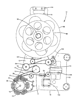
A labeller according to one embodiment of the present invention is shown
in Fig. 1 and generally designated 10. The labeller 10 includes a frame 12
supporting a
plurality of labeller components, including a label wheel 86, a peel plate 28,
a drive wheel
17, a tamping bellows 30, and a waste liner rewind wheel 88. The label wheel
86 is
mounted on a rotatable shaft 90 extending from the frame 12 and is capable of
supporting
4
SUBSTITUTE SHEET (RULE 26)
CA 02723478 2010-11-04
WO 2009/135293 PCT/CA2009/000587
a label web including a release liner 11 carrying a plurality of labels. The
peel plate 28 is
mounted to the frame 12 adjacent to the tamping bellows 30 and includes a
terminal end
31, around which the label web can be drawn to separate the labels from the
release liner
11. The drive wheel 17 is capable of pulling the release liner from the label
wheel 86 and
around the terminal end 31 of the peel plate 28. The tamping bellows 30
includes a
tamping face 32 that is movable between a retracted position and an extended
tamping
position in which the tamping face can engage the labels as they are separated
from the
release liner 11. The rewind wheel 88 is rotatably mounted on the shaft 90 and
is capable
of supporting the release liner 11 by winding the release liner about the
shaft 90.
I. Structure
The frame 12 may be configured to contain or support a variety of the
labeller head and cassette components, such as the labeller components
described in detail
in U.S. Patents 6,729,375; 7,153,378; 7,158,574; and 7,363,954. The labeller
components
may be directly or indirectly attached to the frame. Optionally, the labeller
10 can be a
one-piece labeller that includes a rear frame 12 that is formed from a single
piece. The
frame 12 can be formed in any suitable size and shape and formed from a wide
variety of
materials, such as molded plastic or metal.
In the embodiment illustrated in Figs. 1-10, the frame 12 includes a top
edge 14 forming a handle 16, a bottom edge 18, a left side 20 and a right side
22. The
corner formed between the bottom edge 18 and left side 20 may include a
rounded
extension to support a turret 26, which is adapted to support and rotate the
bellows 30, as
will be discussed below. The single frame 12 may also incorporate all required
controls to
become a "stand-alone" tamping bellows labeller, as also discussed below. The
single
frame 12 may also incorporate other designs or parts that form a tamping
bellows labeller.
The peel plate 28 can be formed in any suitable shape and size and can
include an upper surface 33 and a lower surface 35. In the illustrated
embodiment, the
terminal end 31 of the peel plate 28 is of a sufficient width such that the
individual labels
are peeled from the support wheel when they pass across the lower surface 35
and turn
about the terminal end 31. The peel plate 28 is positioned adjacent the
bellows 30, such
that as the individual labels are peeled from the wheel, they can each be
placed on the
tamping face of a bellows 30.
Each bellows 30 is adapted to extend to tamp the label from the tamping
face 32 of the bellows onto an object, such as an item of produce. The
labeller 10 can
5
SUBSTITUTE SHEET (RULE 26)
CA 02723478 2010-11-04
WO 2009/135293 PCT/CA2009/000587
include single or multiple, stationary or moving tamping bellows. The bellows
30 can be
located above or below the peel plate 28 to receive labels as they are peeled
from the
release liner 11. Each bellows 30 can be formed from a flexible material, such
as rubber
or silicone. In the illustrated embodiment, the bellows 30 has a series of
accordion-like
folds, such that the bellows 30 is capable of extending outward to place the
labels on the
products.
The tamping face 32 of each bellows 30 is perforated with holes 33. In'one
embodiment, the label is held on the tamping face 32 via vacuum pressure
communicated
through the vacuum holes 33 (Figs. 12-13). The label can be deposited on the
item by
switching off the vacuum source 43 when the bellows 30 is in an extended
position. The
bellows 30 may be extended into the extended position by a positive pressure
source 41
provided in the bellows 30. In one embodiment, both the vacuum and pressure
supplies 43
and 41 can be provided by an electric and/or pneumatic valve, such as the
pneumatic valve
110 shown in Fig. 35, which may be mounted to the frame 12. However, any other
suitable means for providing a vacuum source or a positive pressure source can
be used.
In the illustrated embodiment, the multiple bellows 30 are mounted to a
rotating turret 26. Figs. 1-10 show an embodiment with a rotating turret 26
positioned
below the peel plate 28. As shown in Figs. 32-34, in another embodiment, the
rotating
turret 26 can alternatively be positioned above the peel plate 29. Figs. 11-26
show a
turret 26 and axle or shaft 19. As shown, the axle is a rotating shaft 19
mounted to the
frame 12. In the illustrated embodiment, the shaft 19 extends through the
frame 12 and
supports a gear 40 on the opposite side of the frame 12 as the turret 26
(Figs. 14 and 21).
The gear 40 may be driven by a variety of means to rotate the turret 26, such
as a belt
drive (not shown). In one embodiment, the gear 40 is driven by a belt that
also drives
other labeller components. In another embodiment, the gear 40 is driven by a
dedicated
belt drive, or another type of drive.
As shown in Fig. 19, air pressure 42 and vacuum 44 ports are mounted to
and/or moulded into a plate 46 that is formed as part of the main frame 12 or
attached to
the main frame 12 as a separate piece. In the illustrated embodiment, pressure
42 and
vacuum 44 port holes are located on a porting surface 51 of the plate 46 such
that they are
adjacent to the side of the turret 26. As shown in Figs. 22-26, the turret 26
includes an
inner surface 50 facing the porting surface 51. The inner surface 50 defines a
plurality of
port holes 52, with one port hole 52 for each bellows 30 attached to the
turret 26. Each
6
SUBSTITUTE SHEET (RULE 26)
CA 02723478 2010-11-04
WO 2009/135293 PCT/CA2009/000587
port hole 52 extends through the turret 26 forming an air passage to an exit
hole 54 on the
circumferential face of the turret 26. Each bellows 30 is attached over top of
one of the
exit holes 54. As shown in Fig. 19, the vacuum port 44 extends from an intake
56 to form
a horseshoe shape around substantially all of the axle hole. The pressure port
42 extends
from an intake 58 to a position adjacent the axle hole within the gap formed
by the
vacuum port 44.
In one embodiment, the turret 26 rotates on the axle and against the porting
surface 51, which may be a low friction material (i.e. stainless steel) or low-
friction coated
metal or plastic or a mechanical bearing (i.e. lazy Susan). As the turret 26
rotates, the port
holes 52 are in fluid communication with the vacuum port 44 and the pressure
port 42.
More particularly, in the illustrated embodiment, the port holes 52 are
generally in fluid
communication with the horseshoe shaped vacuum port 44, such that the bellows
30 and
tamping face are in fluid communication with the vacuum to hold the bellows in
a
retracted position and to hold a label on the tamping face. When the bellows
30 pass the
pressure port 44, however, the port holes 52 and bellows 30 are in fluid
communication
with the positive pressure to extend the bellows and release the label.
The peel plate 28 (or 29) can be formed in any suitable shape and size. In
the illustrated embodiment, the peel plate is generally square in shape, with
the release
liner traveling lengthwise across the plate 28 (Fig. 1). The release liner 11
is wrapped
around the peel plate 28, such that when the release liner 11 reaches the end
of the peel
plate 28, the label peels off of the release liner 11. One of the bellows 30
that is positioned
adjacent the peel plate can then grab the label as it is peeled from the
release liner 11.
Optionally, the peel plate 28 (or 29) may be adapted to move in and out or up
and down or
sideways to release labels from the liner to be picked up by the bellows 30.
For example,
in the embodiment shown in Figs. 35-38, the peel plate 29 is movable forward
and
backward with respect to the frame 112 as a result of a rack 114 and pinion
116
arrangement mounted on the frame 112.
The label position on the bellows 30 may be determined by a combination
of one or more sensors to detect label position and/or the position of the
waste liner drive
roller pins. For example, the label position on the bellows 30 may be
determined by a
label sensor 34 (Fig. 32). The label position on the bellows 30 may also be
determined by
a sensor 36 that detects the position of the waste liner drive roller pins.
The sensors 34
7
SUBSTITUTE SHEET (RULE 26)
CA 02723478 2010-11-04
WO 2009/135293 PCT/CA2009/000587
and 36 may be a combination of one or more photo optic, laser, inductive,
capacitive, or
other electrical/electronic sensors.
The label position on the bellow 30 may be additionally or alternatively be
determined by a toothed belt or gear, or multiple belts or gears, that
mechanically
synchronize the label and bellow positions. For example, the label position on
the bellows
30 may be determined by electrically or mechanically synchronizing two or more
drives
that separately drive the label feed and/or rewind and/or turret 26 and/or
print mechanism
(discussed below).
In one embodiment, the labeller 10 includes a printing mechanism 104
adapted to print a desired printed material on the labels before they are
placed onto
objects. The printing mechanism 104 can be mounted on the frame 12 at one or
more
label positions prior to the peel plate dispensing edge to print real-time,
variable, or the
same product information and/or identification. The printing mechanism 104 can
otherwise be mounted at the end of the peel plate to print the labels as they
are dispensed,
to print real-time, variable, or the same product information and/or
identification. The
print mechanism may be one of a variety of print technologies, including ink
jet, direct
thermal, thermal transfer, laser, ultra-violet or special light reactive. In
one embodiment,
the printing mechanism 104 may be moveable along the label path in one or more
directions, for instance, to enable printing the printed information on the
label while the
label is not in motion.
In the illustrated embodiment, label web 11 is routed from the label wheel
86 around a label pinch roller 103, shown in Fig. 2, which holds the label web
11 firmly
on in place on the roller 103. This prevents the liner from moving and/or
stretching as the
liner tension swing arm 107, which adjusts and maintains label web tension,
and can cause
the roll to stop abruptly, and controls the position of the printed image
(known as "print
registration") on the label web 11. An electronic positioning device, such as
a rotary
encoder 105 (Fig. 2), may be attached to an idler roller that is located
before or after the
print mechanism to precisely control the angle of rotation of the idler roller
in order to
properly register a label for printing.
In one embodiment, the print mechanism 104 is electrically coupled to a
system controller (not shown) and a user input interface (not shown). The
controller may
be programmed to allow a user to input a desired print type and control the
print
mechanism to output labels with that print type. The print mechanism and/or
controller
8
SUBSTITUTE SHEET (RULE 26)
CA 02723478 2010-11-04
WO 2009/135293 PCT/CA2009/000587
may incorporate software or hardware speed and/or position sensing device to
signal and
control the printer to print the information while matching the label
dispensing speed to
maintain accurate print location on the labels. In one embodiment, the encoder
103 may
be electrically connected to the controller to control the print mechanism
and/or signal the
software to improve the print registration and/or print image quality (i.e.
contrast,
darkness, dpi).
In the illustrated embodiment, the label wheel 86 and rewind wheel 88 are
formed as a multi-disc assembly that supports both the pre-loaded label roll
and waste
liner together on the rotating rewind shaft 90. For example, Figs. 27-31 show
a rewind
assembly 61 that includes a first disc 60 adjacent to the frame 12, a second
disc 62, and a
third disc 64. The label web or roll can be supported between the first 60 and
second 62
discs, such that the roll rotates about a label hub 66 that engages and
rotates with the shaft.
The waste liner 13, which remains on the labeller 10 after the labels have
been removed
and applied to products, may be wound onto the rewind hub 92 between the
second 62 and
third 64 discs.
In this embodiment, both the label web and the waste liner 13 are wound
around the same axis, which would typically rotate both the label wheel 86 and
the rewind
wheel 88 at the same speed. However, the radius of the label web is typically
larger than
that of the waste liner on the rewind wheel, because as the labeller 10 begins
to operate,
the rewind hub 92 is empty and only accumulates waste liner as the labels are
pulled from
the liner 11. Thus, to account for the fact that the distance that the label
rewind hub 92
must rotate to wind a particular amount of waste liner 13 decreases as the
diameter of the
waste liner 13 increases, the labeller 10 can include a mechanism, such as
gripping
mechanism 63, which is incorporated in the rewind disc assembly 61 to alter
the speed of
the rewind wheel with respect to the shaft 90. The gripping mechanism 63 holds
the
rewind disc assembly 61 on the rotating rewind shaft 90 during the rewind
operation to
provide a mechanical "slipping" action as the rotating rewind shaft 90 is
rotated faster than
the rewind disc assembly, in order to rewind and maintain tension on the waste
liner. As
shown, the label rewind assembly includes a label rewind core 70 that mounts
directly
onto the shaft and rotates at the same rate of the shaft, and a rewind hub 72
that rotates
about the label rewind core 70.
As shown in Fig. 27, in one embodiment, the gripping mechanism 63 may
include one or more spring loaded gripping elements 80 that are fitted into
notches 82 in
9
SUBSTITUTE SHEET (RULE 26)
CA 02723478 2010-11-04
WO 2009/135293 PCT/CA2009/000587
the inside of the rewind hub. More particularly, the gripping elements 80 are
small blocks
of any of a variety of materials that include cutouts to receive springs 81.
The gripping
elements 80 put a desired degree of tension on the label rewind core, such
that the rewind
hub 92 rotates with the core, but is capable of slipping with respect to the
core. In one
embodiment, the rate of rotation of the axle is such that the rewind hub 92
always slips
with respect to the core. The amount of slip can increase as the diameter of
the waste liner
on the rewind hub 92 increases. In another embodiment, an alternative clutch
mechanism
may be attached to the rewind disc assembly 61.
Optionally, the waste liner rewind hub 92 may include an indent 84 in the
outer circumference of the hub to allow a finger or other device to be placed
under the
rewound waste liner to improve and simplify removal of the waste liner. The
waste liner
hub 92 may be removable from the labeller 10, for instance, by pulling the
rewind hub 92
and the third disc 64 off the labeller.
One of the waste liner rewind discs 62 or 64 can include a pin or other
device (not shown) inserted or rotated in the outer circumference of the hub
to extend the
hub outer circumference while the waste liner is being rewound. The device
could be
removed or rotated to decrease the waste liner rewind disc circumference
making it easier
to remove the waste liner by decreasing the of the waste liner tension against
the waste
liner rewind disc.
The rotating components of the labeller 10 can be driven by any suitable
drive arrangement. In one embodiment, the labeller includes a single drive
motor 100,
connected to the drive wheel 17 for driving the various labeller components.
The drive
motor 100 drives the drive wheel 17 to rotate, which may drive the label web,
label wheel,
and waste liner wheel to rotate by pulling the release liner. Multiple gears
(such as the
drive wheel gear 98 and the turret gear 40 shown in Fig. 3) may be linked
together with
one or more intermediate gears (not shown), or one or more belts to drive the
individual
components. In another embodiment, labeller 10 may be driven by multiple
drives 100
that are be synchronised to move and/or rotate the various components in time
with each
other and/or at different speeds and/or different intervals during the label
dispense and
application cycle.
The labeller drive 100 may be a DC electric motor, an AC electric motor, a
stepper motor, a servo motor, a pneumatic or hydraulic motor, an electric or
pneumatic or
hydraulic linear or rotary cylinder (Fig. 32). The labeller drive can
optionally start and
SUBSTITUTE SHEET (RULE 26)
CA 02723478 2010-11-04
WO 2009/135293 PCT/CA2009/000587
stop intermittently or operate continuously. The cycle activation of the
labeller drive 100
can be electrically connected to the controller to signal the motor to start
and/or stop
intermittently or continuously as a function of another one of the labeller
components,
such as the encoder output, print mechanism output, or an external sensor
output signal.
The external sensor 102 may be used to control the speed of the labeller 10.
In one
embodiment, the sensor 102 may be a photo-optic, inductive, capacitive,
ultrasonic, laser
or mechanical switch that can detect the product and/or support mechanisms,
calculate the
product speed and signal the controller to adjust the labeller speed.
II. Operation
In operation, the labeller 10 may begin by actuating the drive motor 100 to
begin indexing the label web 11. The motor 100 may be electrically connected
to the
controller and a under input interface, such that the motor 100 is actuate by
the controller
after a particular input by the user. When the motor is actuated, the drive
wheel 17 rotates
at least an amount to index one label past the peel plate and onto the tamping
face 32 of a
bellows 30. In one embodiment, the drive wheel 17 may include a series of
protrusions
around its circumference that interfit with holes in the release liner to aid
in pulling the
label web I1 from the label wheel and around the various idler pulleys and
other
components to the peel plate 28. The rotation of the drive wheel 17 alone may
pull the
label web 11 off the label wheel 86 and around the peel plate 28, and may pull
the waste
release liner 13 onto the rewind wheel 88. In another embodiment, the drive
gear 98
opposite the drive wheel 17 may be connected to other labeller components,
such as the
label wheel 86 and rewind wheel 88 to aid in driving the label web 11.
As the label web I1 is pulled around the peel plate 28, the labels are
separated from the release liner 13. The release liner 13 is then pulled
around the drive
wheel 17, and the tapered pulleys 94, which help to direct the release liner
on to the
rewind wheel 88. The release liner is pulled around the pulley held by the
tension arm
107, and wound onto the rewind wheel 88. As noted above, as additional release
liner 13
is pulled onto the rewind wheel 88, the slip mechanism allows the hub 92 to
slip with
respect to the core 70, which accounts for the fact that the distance that the
label rewind
hub 92 must rotate to wind a particular amount of waste liner 13 decreases as
the diameter
of the waste liner 13 increases. In one embodiment, the rewind wheel may be
large
enough to accommodate the release liner 13 from an entire label web roll, such
that the
11
SUBSTITUTE SHEET (RULE 26)
CA 02723478 2010-11-04
WO 2009/135293 PCT/CA2009/000587
rewind wheel 88 does not need to be removed and emptied until the label roll
has been
completely used.
In an embodiment including a print mechanism, as the label web 11 is
indexed, the print mechanism 104 may print a desired printed material onto
each
individual label. The print registration is controlled by the pinch roller 103
and the
encoder 105, which may interact with the controller and a user input interface
to print the
correct printed material at the correct location and with the correct contrast
and resolution.
As the labels are indexed over the peel plate 28, the position of the labels
may be monitored by a sensor 34, such as an optical sensor, which may
communicate with
the controller to actuate the motor 100, or another motor, to drive the turret
gear 40 and the
turret 26. The turret then rotates to move a tamping bellows 30 to the label
position,
wherein the bellows 30 communicates with the positive pressure source via the
positive
pressure port 42 to extend the bellows 30 and tamp the label onto a product.
The above description is that of the current embodiment of the invention.
Various alterations and changes can be made without departing from the spirit
and broader
aspects of the invention as defined in the appended claims, which are to be
interpreted in
accordance with the principles of patent law including the doctrine of
equivalents. Any
reference to claim elements in the singular, for example, using the articles
"a," "an," "the"
or "said," is not to be construed as limiting the element to the singular.
12
SUBSTITUTE SHEET (RULE 26)