Note: Descriptions are shown in the official language in which they were submitted.
CA 02723518 2010-12-02
ACTIVATING MOTION DETECTORS
BACKGROUND INFORMATION
1. Field:
The present disclosure relates generally to motion detectors and, in
particular, to a
method and apparatus for activating motion detectors. Still more particularly,
the
present disclosure relates to a method and apparatus for activating motion
detectors to
determine whether a working motion detector is present.
2. Background:
A motion detector is a device that contains a mechanism that quantifies
motion. For
example, a motion detector can transform the detection of motion into an
electrical
signal.
This type of motion detector typically measures optical, thermal, or
acoustical changes
in an area around the motion detector. The area that the motion detector
detects
motion is also referred to as a field of view. Many motion detectors can
detect motion at
a distance from about 50 feet to about 80 feet.
A motion detector may be used to control the operation of a device. For
example, a
motion detector may initiate the operation of the device, stop the operation
of the
device, or change the manner in which the device operates.
Motion detectors have a number of different uses. For example, motion
detectors are
used in buildings to open automatic doors. As another example, motion
detectors may
be used to turn on lights, activate escalators, turn off water sprinklers, and
provide other
suitable operations.
Additionally, motion detectors also are used to alert an organization to a
presence of
people in different areas. For example, motion detectors may be used in a
security
system to detect a presence of unauthorized people in a particular location.
1
CA 02723518 2013-08-23
Although motion detectors are useful, these types of systems do require
maintenance.
For example, if a motion detector fails to function as desired, then the
particular system
the motion detector is desired to control may not be operated as desired. In
this
situation, the motion detector is reworked or replaced.
For example, if a motion detector used to control lights is not functioning as
desired,
lights may not turn on or turn off as desired. As another example, if a motion
detector
does not work properly, a person may have to slow down or stop before entering
a
building with a door opened by a motion detector. In this case, the motion
detector
operates, but not as desired. The motion detector does not detect the person
far
enough away to open the door in a manner that avoids the person having to slow
down
or stop. In these situations, the motion detector may require reworking or
replacement.
Reworking may involve changing the sensitivity of the motion detector.
Accordingly, it would be advantageous to have a method and apparatus which
takes
into account one or more of the issues discussed above, as well as possibly
other
issues.
SUMMARY
In one advantageous embodiment, an apparatus comprises a transmitter system
and a
controller. The transmitter system is configured to transmit electromagnetic
signals in
the form of a beam. The controller is configured to cause the transmitter
system to
transmit the beam such that a motion detector is activated when the beam
encounters
the motion detector.
In another advantageous embodiment, a method is present for activating a
motion
detector. An electromagnetic signal is transmitted in a form of a beam. The
beam is
configured to activate the motion detector when the beam encounters the motion
detector. The beam is moved to a location in which the motion detector is
present such
that the motion detector activates.
According to another embodiment, there is provided an apparatus including a
transmitter system configured to transmit electromagnetic signals in a form of
a beam.
2
CA 02723518 2013-08-23
The apparatus also includes a controller configured to cause the transmitter
system to
transmit the beam such that a motion detector is activated when the beam
encounters
the motion detector. The controller is configured to select a number of
frequencies for
the beam to couple to a number of electrical components in the motion detector
and
transmit the beam with the number of frequencies such that the beam couples to
the
number of electrical components in the motion detector in a manner that
activates the
motion detector when the motion detector device encounters the beam.
The motion detector may be a passive motion detector.
The transmitter system may include a signal generator configured to generate
the
electromagnetic signals and an antenna system configured to transmit the
electromagnetic signals in the form of the beam.
The signal generator may include a radio frequency generator configured to
generate
the electromagnetic signal in a form of radio frequency signals having a
wavelength
from about 75 GHz to about 110 GHz.
The antenna system may include a Gaussian optical antenna.
The beam may be a radio frequency beam.
The beam may be a substantially collimated radio frequency beam.
The apparatus may further include a platform. The transmitter system and the
controller
may be associated with the platform.
The platform may be selected from one of a moving platform, a stationery
platform, a
vehicle, a truck, a helicopter, an aircraft, a portable housing, and a
building.
According to another embodiment, there is provided a method for activating a
motion
detector. The method involves transmitting an electromagnetic signal in a form
of a
beam, wherein the beam is configured to activate the motion
2a
CA 02723518 2013-08-23
detector when the beam encounters the motion detector, and moving the beam to
a
location in which the motion detector is present such that the motion detector
activates.
The method also involves controlling the transmitting the electromagnetic
signal in the
form of a beam so as to select a number of frequencies for the beam to couple
to a
number of electrical components in the motion detector and transmit the beam
with the
number of frequencies such that the beam couples to the number of electrical
components in the motion detector in a manner that activates the motion
detector when
the motion detector device encounters the beam.
The method may further involve moving the beam to a number of other locations.
A
number of other motion detectors in the number of other locations may be
activated
when the beam encounters the number of other motion detectors.
The step of transmitting the electromagnetic signal in the form of the beam,
wherein the
beam is configured to activate the motion detector when the beam encounters
the
motion detector, may involve generating the electromagnetic signal using a
signal
generator in a transmitter and transmitting the electromagnetic signal as the
beam using
an antenna system.
The method may further involve amplifying the electromagnetic signal using an
amplifier
after generating the electromagnetic signal using the signal generator and
before
transmitting the electromagnetic signal as the beam using the antenna system.
The signal generator may include a radio frequency generator configured to
generate
the electromagnetic signal in a form of radio frequency signals having a
wavelength
from about 75 GHz to about 110 GHz.
The antenna system may include a Gaussian optical antenna.
The beam may be a radio frequency beam.
The beam may be a substantially collimated radio frequency beam.
2b
CA 02723518 2013-08-23
The electromagnetic signals may be transmitted in the form of the beam using a
transmitter system associated with a platform.
The platform may be selected from one of a moving platform, a stationery
platform, a
vehicle, a truck, a helicopter, an aircraft, a portable housing, and a
building.
The features, functions, and advantages can be achieved independently in
various
embodiments of the present disclosure or may be combined in yet other
embodiments
2c
CA 02723518 2010-12-02
in which further details can be seen with reference to the following
description and
drawings.
BRIEF DESCRIPTION OF THE DRAWINGS
The novel features believed characteristic of the advantageous embodiments are
set
forth in the appended claims. The advantageous embodiments, however, as well
as a
preferred mode of use, further objectives and advantages thereof, will best be
understood by reference to the following detailed description of an
advantageous
embodiment of the present disclosure when read in conjunction with the
accompanying
drawings, wherein:
Figure 1 is an illustration of a motion detector environment in accordance
with an
advantageous embodiment;
Figure 2 is an illustration of a motion detector environment in accordance
with an
advantageous embodiment;
Figure 3 is an illustration of an activation system in accordance with an
advantageous
embodiment; and
Figure 4 is an illustration of a flowchart of a process for activating a
motion detector in
accordance with an advantageous embodiment.
DETAILED DESCRIPTION
The different advantageous embodiments recognize and take into account a
number of
different considerations. For example, the different advantageous embodiments
recognize and take into account that in performing maintenance, it is often
desirable to
determine whether motion detectors are working as desired. In other words,
motion
detectors may be tested to determine whether they become activated in the
desired
circumstances. For example, the motion detectors may be tested to determine
whether
they activate, whether they activate within a certain distance, whether they
activate
within a certain field of view, and other suitable situations in which motion
detectors are
activated.
3
CA 02723518 2010-12-02
One manner in which motion detectors can be tested involves having personnel
test
each motion detector. With this type of testing, a person moves into each area
in which
a motion detector is present. When the person moves into the area, a
determination is
made as to whether the device operated by the motion detector is activated in
response
to motion by the person. This determination may be made by seeing whether the
device operates. For example, lights may turn on, a panel may indicate the
presence of
motion, or some other suitable operation.
The different advantageous embodiments recognize and take into account that
this type
of testing of motion detectors, however, is time consuming. The testing
requires a
person to move to each area in which a motion detector is present.
Thus, the advantageous embodiments provide a method and apparatus for
activating a
motion detector. This activation is used to cause the device connected to the
motion
detector to operate. In this manner, one or more of the different advantageous
embodiments may be used to determine whether a motion detector is operating.
In one advantageous embodiment, an apparatus comprises a transmitter system
and a
controller. The transmitter system is configured to transmit electromagnetic
signals in
the form of a beam. The controller is configured to cause the transmitter
system to
transmit the beam such that a motion detector is activated when the motion
detector
encounters the beam.
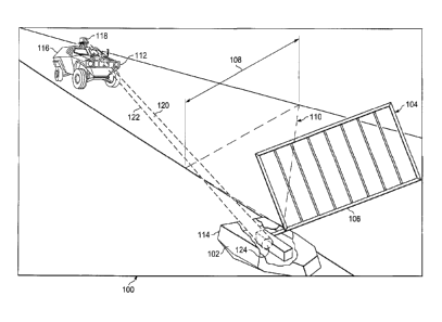
With reference now to Figure 1, an illustration of a motion detector
environment is
depicted in accordance with an advantageous embodiment. In this illustrative
example,
motion detector environment 100 includes motion detector 102 and device 104.
In this
example, device 104 takes the form of powered gate 106. Motion detector 102 is
connected to powered gate 106 and moves powered gate 106 when an object is
detected within selected distance 108 and field of view 110 of motion detector
102.
Activation system 112 may be used to detect the presence of motion detector
102 in
location 114 or test the operation of motion detector 102 in location 114. In
this
illustrative example, activation system 112 comprises vehicle 116 with
transmitter 118.
4
CA 02723518 2010-12-02
Transmitter 118 is configured to transmit electromagnetic signals 120 in the
form of
beam 122. In these examples, beam 122 is a collimated beam. When end 124 of
beam 122 reaches motion detector 102 at location 114, motion detector 102 is
activated
to cause powered gate 106 to move. In this manner, an operator of vehicle 116
may
test the operation of motion detector 102 and powered gate 106 without having
to move
vehicle 116 into a location for detection by motion detector 102.
In this manner, operator of vehicle 116 may test various motion detectors for
other
devices, such as other powered gates, security systems, and/or other devices
more
quickly than moving vehicle 116 to the appropriate position within field of
view 110.
Further, in some cases, testing of motion detectors may require the operator
to leave
vehicle 116 and move into the desired location.
Turning now to Figure 2, an illustration of a motion detector environment is
depicted in
accordance with an advantageous embodiment. Motion detector environment 100 in
Figure 1 is an example of one implementation of motion detector environment
200 in
Figure 2. Motion detector environment 200 includes number of motion detectors
202 in
number of locations 204. Number of motion detectors 202 is connected to number
of
devices 206.
As used herein, when a first component is connected to a second component, the
first
component may be connected to the second component without any additional
components. The first component also may be connected to the second component
by
one or more other components. For example, one electronic device may be
connected
to another electronic device without any additional electronic devices between
them. In
some cases, another electronic device may be present between the two
electronic
devices connected to each other.
In these illustrative examples, activation system 208 may be used to determine
whether
number of motion detectors 202 in number of locations 204 is working. Further,
activation system 208 may be used to detect a presence of number of motion
detectors
202 in number of locations 204.
CA 02723518 2010-12-02
For example, the presence of number of motion detectors 202 in number of
locations
204 may be detected when number of devices 206 connected to number of motion
detectors 202 begin operating, cease operating, and/or change the manner in
which
number of devices 206 operate.
In this illustrative example, activation system 208 comprises transmitter
system 210 and
controller 212. Transmitter system 210 is configured to transmit
electromagnetic signals
214 in a manner that activates any of number of motion detectors 202. If any
of number
of motion detectors 202 do not activate, those motion detectors may be non-
operational
or not functioning as desired or expected.
In these illustrative examples, transmitter system 210 is configured to
transmit
electromagnetic signals 214 in the form of beam 216. In particular, beam 216
is
substantially collimated beam 218 in these illustrative examples. A
substantially
collimated beam is a propagation of electromagnetic signals 214 in a beam that
travels
with substantially diffraction-limited divergence as the beam travels away
from the
transmitter. In other words, the substantially collimated beam travels with
substantially
the same diameter or cross-section along the beam. This type of propagation of
electromagnetic signals 214 is in contrast to electromagnetic signals 214
radiating in
many directions.
Electromagnetic signals 214 have frequency 220 and power level 222. In these
illustrative examples, beam 216 may be moved across area 224, which includes
number of locations 204. If number of locations 204 is known for number of
motion
detectors 202 within area 224, beam 216 may be directed at each of number of
locations 204 to test number of motion detectors 202.
If number of locations 204 for some or all of number of motion detectors 202
is
unknown, beam 216 may be moved to cover area 224. In this manner, a presence
of
number of motion detectors 202 may be detected. Further, number of locations
204 for
number of motion detectors 202 also may be detected by identifying the
location of end
225 of beam 216 in area 224.
6
CA 02723518 2010-12-02
In these illustrative examples, at least one of frequency 220 and power level
222 for
electromagnetic signals 214 in beam 216 are selected such that a motion
detector, such
as motion detector 226 in number of motion detectors 202 in number of
locations 204, is
activated when motion detector 226 encounters end 225 of beam 216. In these
examples, motion detector 226 includes number of electrical components 230.
At least one of frequency 220 and power level 222 are selected such that
electromagnetic signals 214 in beam 216 are coupled to number of electrical
components 230.
As used herein, the phrase "at least one of", when used with a list of items,
means that
different combinations of one or more of the listed items may be used and only
one of
each item in the list may be needed. For example, "at least one of item A,
item B, and
item C" may include, for example, without limitation, item A or item A and
item B. This
example also may include item A, item B, and item C, or item B and item C.
This coupling of electromagnetic signals 214 to number of electrical
components 230 is
in a manner that activates motion detector 226. The activation of motion
detector 226 is
an activation indicating that motion 232 has been detected by motion detector
226.
In these illustrative examples, motion detector 226 may be passive motion
detector 234,
active motion detector 236, and/or a combination of the two. Passive motion
detector
234 may use infrared sensors. Active motion detector 236 may use sensors that
detect
ultrasonic and/or microwave signals that may be emitted by active motion
detector 236.
The illustration of motion detector environment 200 in Figure 2 is not meant
to imply
physical or architectural limitations to the manner in which different
advantageous
embodiments may be implemented. Other components in addition and/or in place
of
the ones illustrated may be used. Some components may be unnecessary in some
advantageous embodiments. Also, the blocks are presented to illustrate some
functional components. One or more of these blocks may be combined and/or
divided
into different blocks when implemented in different advantageous embodiments.
7
CA 02723518 2010-12-02
For example, in some advantageous embodiments, transmitter system 210 may
transmit electromagnetic signals 214 in the form of two beams. For example,
electromagnetic signals 214 may form beam 216 and beam 244. Beam 216 and beam
244 may be directed at different locations in area 224.
In yet other advantageous embodiments, beam 216 and beam 244 may overlap at a
location in area 224. In still other advantageous embodiments, beam 216 and
beam
244 may have different frequencies. Difference frequency is the difference
between
beam 216 and beam 244. The difference frequency may be the frequency selected
to
cause electromagnetic signals 214 to couple with number of electrical
components 230
in these illustrative examples.
In still other illustrative examples, activation system 208 also may include
platform 242.
Platform 242 may be associated with activation system 208 in transmitter
system 210.
For example, without limitation, platform 242 may be a moving platform, a
stationery
platform, a vehicle, a truck, a helicopter, an aircraft, a portable housing, a
building, or
some other suitable type of platform.
With reference now to Figure 3, an illustration of an activation system is
depicted in
accordance with an advantageous embodiment. In this illustrative example,
activation
system 300 is an example of one implementation of activation system 208 in
Figure 2.
As depicted, activation system 300 includes platform 302, transmitter system
304, and
controller 306. Transmitter system 304 and controller 306 are associated with
platform
302.
A first component may be considered to be associated with a second component
by
being secured to the second component, bonded to the second component,
fastened to
the second component, and/or connected to the second component in some other
suitable manner. The first component also may be connected to the second
component
through using a third component. The first component may also be considered to
be
associated with the second component by being formed as part of and/or an
extension
of the second component.
8
CA 02723518 2010-12-02
In this example, transmitter system 304 includes signal generator 308,
amplifier 310,
and antenna system 312. Signal generator 308 is connected to antenna system
312
through amplifier 310. Signal generator 308 generates electromagnetic signals
314.
Amplifier 310 amplifies electromagnetic signals 314. In turn, electromagnetic
signals
314 are sent to antenna system 312, which transmits electromagnetic signals
314 as
beam 316.
Signal generator 308, in these illustrative examples, may be implemented using
a
number of different components. For example, without limitation, signal
generator 308
may be implemented using synthesizer 317 and mixer 318.
In these illustrative examples, controller 306 may be implemented using a
number of
different devices. For example, controller 306 may comprise at least one of a
processor
unit, an application specific integrated circuit, or some other suitable
device. A
processor unit may have one or more microprocessors. For example, a processor
unit
may be a multi-core processor or some other suitable type of processing
system.
In these illustrative examples, controller 306 controls transmitter system 304
to control
at least one of frequency 319 and power level 321 of electromagnetic signals
314. Of
course, controller 306 also may control other characteristics of
electromagnetic signals
314. For example, a phase of electromagnetic signals 314 also may be
controlled.
In these illustrative examples, signal generator 308 generates electromagnetic
signals
314 with frequency 319 from about 75 GHz to about 110 GHz. This type of signal
generator is also referred to as a W-band RF signal generator.
In these examples, antenna system 312 may be implemented using Gaussian
optical
antenna 313. This type of antenna transmits electromagnetic signals 314 in the
form of
beam 316 having a substantially collimated form. In other words, beam 316 is a
substantially collimated beam in these examples.
In these illustrative examples, when beam 316 encounters motion detector 320,
motion
detector 320 is activated. In these illustrative examples, motion detector 320
includes
number of electrical components 322. Number of electrical components 322
includes,
9
CA 02723518 2010-12-02
for example, without limitation, at least one of electrical wires 324, chips
326, printed
wiring board traces 328, and other suitable types of components.
In this example, voltage 330 in number of electrical components 322 may be
changed
such that motion detector 320 is activated. In other words, voltage 330 and
motion
detector 320 may be changed within number of electrical components 322 such
that
motion detector 320 is activated in the same manner that motion would activate
motion
detector 320.
Further, electromagnetic signals 314 in beam 316 also may be configured to
travel
inside of housing 323. For example, electromagnetic signals 314 may be
configured to
pass through materials forming housing 323. In another example,
electromagnetic
signals 314 may pass through holes, cracks, seams, or other openings in
housing 323.
In these illustrative examples, electromagnetic signals 314 may have a power
level that
takes into account any dissipation in power that may occur when traveling
inside of
housing 323 such that electromagnetic signals 314 are capable of coupling to
number of
electrical components 322 in a manner that cause motion detector 320 to become
activated.
The voltage entering the comparator may be changed by beam 316 such that the
comparator indicates a presence of motion. Of course, with other
configurations for
other motion detectors, beam 316 may change other electrical characteristics
of
voltages and/or currents present within motion detector 320.
In this illustrative example, the activation of motion detector 320 causes a
change in
operation 330 of device 332. Device 332 is connected to motion detector 320.
In these
illustrative examples, device 332 may be located in the same location as
motion
detector 320 or in a remote location.
In these illustrative examples, platform 302 may take a number of different
forms. For
example, platform 302 may be a moving platform, a stationery platform, a
vehicle, a
truck, a helicopter, an aircraft, a portable housing, a building, or some
other suitable
type of platform.
CA 02723518 2010-12-02
For example, chips 326 may include a comparator and motion sensors for use in
motion
detector 320. For example, a first motion sensor may detect motion in one
field of view,
while a second motion sensor may detect motion in a second field of view for
motion
detector 320. A difference in light or heat between the two fields of view may
cause a
difference in voltage being sent to the comparator. This difference may
indicate that
motion is present.
The illustration of activation system 300 in Figure 3 is not meant to imply
physical or
architectural limitations to the manner in which different advantageous
embodiments
may be implemented. Other components in addition and/or in place of the ones
illustrated may be used. Some components may be unnecessary in some
advantageous embodiments. Also, the blocks are presented to illustrate some
functional components. One or more of these blocks may be combined and/or
divided
into different blocks when implemented in different advantageous embodiments.
For example, in some advantageous embodiments, antenna system 312 may include
other types of antennas other than Gaussian optical antenna 313. Additionally,
additional numbers of antennas may be present to transmit additional beams,
depending on the particular implementation. Further, in some illustrative
examples,
amplifier 310 may be implemented as part of signal generator 308.
With reference now to Figure 4, an illustration of a flowchart of a process
for activating
a motion detector is depicted in accordance with an advantageous embodiment.
The
process illustrated in Figure 4 may be implemented in motion detector
environment 200
in Figure 2. In particular, the process may be implemented using activation
system 112
in Figure 1.
The process begins by generating an electromagnetic signal (operation 400).
The
electromagnetic signal is generated using activation system 112 in Figure 1.
The
electromagnetic signal is then transmitted in the form of a beam (operation
402). The
beam is configured to activate the motion detector when the beam encounters
the
motion detector.
11
CA 02723518 2010-12-02
The beam may be moved over a location in which a motion detector is present
such that
the motion detector is activated (operation 404), with the process terminating
thereafter.
The movement of the beam may be performed by physically moving the antenna
system, the platform, or other physical components for the activation system.
In other
illustrative examples, the movement of the beam may be performed through
electronic
steering.
Operation 404 may be repeated for a number of different locations. These
locations
may have motion detectors that are known or are visible to an operator. In
some
illustrative examples, the locations may or may not have motion detectors. In
these
situations, the beam may be used to activate motion detectors to identify
their presence.
The presence of motion detectors may be identified by a device connected to
the
motion detector beginning operation, ceasing operation, or changing the manner
in
which the device operates.
The flowcharts and block diagrams in the different depicted embodiments
illustrate the
architecture, functionality, and operation of some possible implementations of
apparatus
and methods in different advantageous embodiments. In this regard, each block
in the
flowchart or block diagrams may represent a module, segment, function, and/or
a
portion of an operation or step. In some alternative implementations, the
function or
functions noted in the block may occur out of the order noted in the figures.
For
example, in some cases, two blocks shown in succession may be executed
substantially concurrently, or the blocks may sometimes be executed in the
reverse
order, depending upon the functionality involved. Also, other blocks may be
added in
addition to the illustrated blocks in a flowchart or block diagram.
Thus, the different advantageous embodiments provide a method and apparatus
for
activating motion detectors. In some illustrative embodiments, an apparatus
comprises
a transmitter system and a controller. The transmitter system is configured to
transmit
electromagnetic signals in the form of a beam. The controller is configured to
cause the
transmitter system to transmit the beam such that a motion detector is
activated when
the beam encounters the motion detector.
12
CA 02723518 2010-12-02
In this manner, motion detectors can be activated during testing and discovery
operations. For example, motion detectors may be tested to determine whether
they
activate under desired conditions. Additionally, a location of motion
detectors may be
identified by activating the motion detectors. The activation of motion
detectors causes
a device connected to the motion detector to operate. This operation may be
used to
indicate the presence of a motion detector in the location where the beam is
directed.
With one or more of the different advantageous embodiments, testing and
locating
motion detectors may be performed more easily. For example, an operator may
direct a
beam from a location over multiple locations to activate motion detectors
rather than
having to travel to each motion detector individually. Further, motion
detectors may be
activated in locations that may be more difficult for an operator to reach.
The description of the different advantageous embodiments has been presented
for
purposes of illustration and description, and is not intended to be exhaustive
or limited
to the embodiments in the form disclosed. Many modifications and variations
will be
apparent to those of ordinary skill in the art.
Further, different advantageous embodiments may provide different advantages
as
compared to other advantageous embodiments. The embodiment or embodiments
selected are chosen and described in order to best explain the principles of
the
embodiments, the practical application, and to enable others of ordinary skill
in the art to
understand the disclosure for various embodiments with various modifications
as are
suited to the particular use contemplated.
13