Note: Descriptions are shown in the official language in which they were submitted.
CA 02723724 2016-03-30
- 1 -
IMPLANTABLE PUMPS AND CANNULAS THEREFOR
Cross-Reference to Related Applications
[0001] This application claims priority to and the benefit of U.S.
Provisional Patent
Application Nos. 61/051,422, which was filed on May 8,2008; 61/197,751, which
was filed on
October 30, 2008; 61/197,769, which was filed on October 30, 2008; 61/198,090,
which was
filed on November 3,2008; and 61/198,131, which was filed on November 3,2008.
Technical Field
[0002] In various embodiments, the invention relates to implantable pumps
and to
cannulas for such pumps.
Background
[0003] Medical treatment often requires the administration of a
therapeutic agent (e.g.,
medicament, drugs, etc.) to a particular part of a patient's body. As patients
live longer and are
diagnosed with chronic and/or debilitating ailments, the likely result will be
an increased need to
place even more protein therapeutics, small-molecule drugs, and other
medications into targeted
areas throughout the patient's body. Some maladies, however, are difficult to
treat with currently
available therapies and/or require administration of drugs to anatomical
regions to which access
is difficult to achieve.
[0004] A patient's eye is a prime example of a difficult-to-reach
anatomical region, and
many vision-threatening diseases, including retinitis pigmentosa, age-related
macular
degeneration (AMD), diabetic retinopathy, and glaucoma, are difficult to treat
with many of the
currently available therapies. For example, oral medications can have systemic
side effects;
topical applications may sting and engender poor patient compliance;
injections generally
CA 02723724 2010-11-05
WO 2009/137780
PCT/US2009/043317
- 2 -
require a medical visit, can be painful, and risk infection; and sustained-
release implants must
typically be removed after their supply is exhausted (and generally offer
limited ability to
change the dose in response to the clinical picture).
[0005] Another example is cancer, such as breast cancer or meningiomas,
where large
doses of highly toxic chemotherapies, such as rapamycin, bevacizumab (e.g.,
Avastin), or
irinotecan (CPT-11), are typically administered to the patient intravenously,
which may result
in numerous undesired side effects outside the targeted area. Yet another
example is drug
delivery to the knee, where drugs often have difficulty penetrating the
avascular cartilage tissue
for diseases such as osteoarthritis.
[0006] Implantable drug-delivery devices, which may have a refillable drug
reservoir, a
cannula for delivering the drug, etc., generally allow for controlled delivery
of pharmaceutical
solutions to a specified target. The devices may be either passively
controlled or actively
controlled. In a passively-controlled device, drug is pumped out when, for
example, a finger is
pressed on the drug reservoir. In an actively-controlled device, drug may be
pumped out
automatically, for example at regular intervals or continuously over time. In
either case, as
drug within the drug reservoir depletes, the physician can refill the
reservoir with, for example,
a syringe, while leaving the device implanted within the patient's body. This
approach can
minimize the surgical incision needed for implantation and typically avoids
future or repeated
invasive surgery or procedures.
[0007] A variety of challenges, however, are associated with refillable
drug-delivery
devices. One limitation of conventional drug-delivery devices is that they are
typically unable
to dynamically respond to changes inside the device (e.g., failures,
blockages, etc.) or to
changes in the drug-delivery target. For example, tissue growth at the outlet
of an implanted
device (e.g., at the outlet of the cannula) may create a fluidic restriction.
In this case, passive
and active drug-delivery devices with no feedback control would likely not
deliver the desired
CA 02723724 2010-11-05
WO 2009/137780
PCT/US2009/043317
- 3 -
flow rate or dose of the drug. Similarly, without feedback, the desired flow
rate or dose may
not be delivered in the presence of temperature fluctuations, where there are
variations in the
drug-delivery device due to varying manufacturing processes, where different
drug
formulations are administered, etc.
[0008] A need exists, therefore, for improved implantable drug-delivery
devices.
Summary of the Invention
[0009] In various embodiments, the present invention features an
implantable drug-delivery
pump that is able to respond to changes that occur inside the pump and/or in
the drug-delivery
target. This ability of the pump improves its therapeutic value, and also
enhances patient
safety. For example, embodiments of the pumps described herein include one or
more flow
sensors for monitoring liquid (e.g., drug) flow through a cannula of the pump.
Where, for
example, the flow rate deviates from a desired rate, circuitry within the pump
may take
corrective action. Alternatively or in addition, the pumps described herein
may include one or
more pressure sensors for monitoring pressure in at least a portion of the
pump. If necessary or
desirable, circuitry within the pump may again adjust the pump operation based
on the
monitored pressure. In various embodiments, the flow sensor(s) is/are
positioned within the
cannula of the pump. The pressure sensor(s) may likewise be so placed, or be
placed at other
locations within the pump.
[0010] Various other components may also be present within, for example,
the pump's
cannula to further assure patient safety. For example, the cannula may include
a filter to
prevent the passage of large particles and possible air bubbles therethrough
and to the patient,
and/or a check valve to prevent backflow from a target site to a drug
reservoir of the pump.
CA 02723724 2016-03-30
- 4 -
[0011] In general, in one aspect, embodiments of the invention feature an
implantable
pump that includes a drug reservoir, a cannula for conducting liquid from the
reservoir, means
for forcing liquid from the reservoir through the cannula, a sensor for
monitoring a parameter
(such as flow rate or pressure) indicative of liquid flowing through the
cannula, and circuitry for
adjusting the forcing means based on the monitored parameter. The sensor may
be manufactured,
at least in part, from parylene, and may be electrically connected to the
circuitry via metal lines
running along the cannula.
[0012] The circuitry may be programmed to deliver a predetermined dosage
of drug
through the cannula, and the sensor may be a flow sensor. For example, the
flow sensor may be a
thermal flow sensor. A thermal flow sensor in accordance herewith may include
a single
element, physically associated with the cannula, that functions both as a
heater and as a
temperature sensor. Alternatively, the thermal flow sensor may include both a
heater and an
independent temperature sensor that are physically associated with the
cannula. The temperature
sensor may be located downstream of the heater. In still another alternative,
the thermal flow
sensor includes a heater and first and second temperature sensors, all of
which are physically
associated with the cannula. The first temperature sensor may be located
downstream of the
heater and the second temperature sensor may be located upstream of the
heater.
[0013] In another embodiment, the flow sensor is a time-of-flight sensor.
A time-of-flight
sensor may include a heater and a first temperature sensor that are both
physically associated
with the cannula. The first temperature sensor may be located downstream of
the heater, and the
circuitry may cause (i) a discrete pulse of power to be applied to the heater
and (ii) detection, by
the first temperature sensor, of liquid heated by the heater. In some cases, a
second temperature
sensor is physically associated with the cannula and located upstream of
CA 02723724 2010-11-05
WO 2009/137780
PCT/US2009/043317
- 5 -
the heater. Alternatively, one or more second temperature sensors may be
physically
associated with the cannula and located downstream of the heater.
[0014] In yet another embodiment, the time-of-flight sensor includes two
upstream
electrodes and two downstream electrodes that are all physically associated
with the cannula.
The circuitry may cause (i) a discrete voltage pulse to be applied across the
two upstream
electrodes and (ii) detection, by the two downstream electrodes, of an
electrochemical pulse
generated in the liquid flowing through the cannula.
[0015] In yet other embodiments, the flow sensor includes a pressure
sensor in the reservoir
and/or one or more pressure sensors in the cannula. Moreover, in addition to
the flow sensor,
the pump may further include a temperature sensor that is not in proximity to
the flowing liquid
and that facilitates compensation for fluctuations in an ambient temperature.
[0016] In various embodiments, the forcing means includes an electrolyte
chamber, an
expandable diaphragm that separates the chamber and the drug reservoir and
that provides a
fluid barrier therebetween, and electrolysis electrodes for causing evolution
of a gas in the
electrolyte chamber to thereby expand the diaphragm so that liquid is forced
from the drug
reservoir into the cannula.
[0017] Alternatively or in addition to a flow sensor, a pressure sensor
may be included to
monitor pressure within the cannula. In one embodiment, the pressure sensor is
located at a
distal end of the cannula (either inside or outside the cannula) for measuring
pressure at the
target site. The circuitry may then adjust pump operation based on the
monitored pressure at
the target site. In another embodiment, the pump includes a check valve in the
cannula, and the
pressure sensor is located inside the cannula and downstream of the check
valve. In yet another
embodiment, the pressure sensor is placed in the drug reservoir or in
proximity to an interface
between the cannula and the drug reservoir.
CA 02723724 2010-11-05
WO 2009/137780
PCT/US2009/043317
- 6 -
[0018] Embodiments including a pressure sensor may also include a flow
sensor for
monitoring a flow rate of the liquid through the cannula. The circuitry may
then detect a pump
malfunction based on the monitored pressure and/or the monitored flow.
[0019] In general, in yet another aspect, embodiments of the invention
feature a cannula for
an implantable pump. The cannula may include an elongate body that has a
channel
therethrough and that narrows at a distal end thereof, a filter integral with
the body at a
proximal end thereof, and means for connecting the proximal end of the body to
a connection
port of the implantable pump. The filter may have a cross-section larger than
the flow cross-
section of the channel, and may define openings that each have a height no
greater than 2 pm.
For example, the filter may include an array of parylene posts that define the
openings.
[0020] In various embodiments, the cannula further includes a flow
sensor for sensing
fluidic flow within the channel, a pressure sensor for sensing pressure at a
site into which the
cannula is inserted, an electrochemical sensor coupled to a distal end of the
elongate body and
on an outside surface thereof, and/or a check valve for preventing a backflow
of fluid in the
channel. The elongate body of the cannula may be manufactured, at least in
part, from
parylene, and at least a portion of the body may be surrounded by a silicone
structure.
[0021] In one embodiment, the cannula's check valve is normally closed
and has a cracking
pressure that is governed by a preloaded force applied to the check valve. The
preloaded force
may be caused by static friction ("stiction") and a difference in height
between two components
of the check valve. The check valve may be manufactured, at least in part,
from layers of
parylene. Moreover, a bonding agent may be applied to the check valve, and/or
the check
valve may include at least one micro heater, in order to maintain the
preloaded force.
[0022] These and other objects, along with advantages and features of
the embodiments of
the present invention herein disclosed, will become more apparent through
reference to the
following description, the accompanying drawings, and the claims. Furthermore,
it is to be
CA 02723724 2010-11-05
WO 2009/137780
PCT/US2009/043317
- 7 -
understood that the features of the various embodiments described herein are
not mutually
exclusive and can exist in various combinations and permutations, even if not
made explicit
herein.
Brief Description of the Drawings
[0023] In the drawings, like reference characters generally refer to the
same parts
throughout the different views. Also, the drawings are not necessarily to
scale, emphasis
instead generally being placed upon illustrating the principles of the
invention. In the
following description, various embodiments of the present invention are
described with
reference to the following drawings, in which:
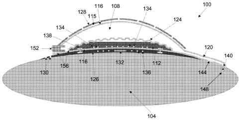
[0024] FIG. lA schematically illustrates, in cross-section, an implantable
drug-delivery
pump in accordance with one embodiment of the invention;
[0025] FIG. 1B schematically illustrates, in cross-section, an
implantable drug-delivery
device in accordance with another embodiment of the invention;
[0026] FIG. 2A schematically illustrates a generalized embodiment of a
flow sensor that
operates based upon thermal effects or time-of-flight;
[0027] FIG. 2B schematically illustrates a capacitive pressure-sensing-
based flow sensor in
accordance with one embodiment of the invention;
[0028] FIGS. 3-5 schematically illustrate thermal-effect flow sensors in
accordance with
various embodiments of the invention;
[0029] FIGS. 6-9 schematically illustrate time-of-flight-based flow sensors
in accordance
with various embodiment of the invention;
[0030] FIGS. 10A and 10B schematically illustrate pressure-sensing-based
flow sensors in
accordance with various embodiments of the invention;
CA 02723724 2010-11-05
WO 2009/137780
PCT/US2009/043317
- 8 -
[0031] FIG. 11 schematically illustrates the placement of various
pressure sensors in an
implantable drug-delivery pump in accordance with one embodiment of the
invention;
[0032] FIG. 12 is a graph illustrating the relationship, under normal
operating conditions,
between the pressure drop across a cannula for a typical implantable drug-
delivery pump and
the rate of fluid flow therethrough;
[0033] FIG. 13 is a schematic sectional view of a cannula in accordance
with one
embodiment of the invention;
[0034] FIG. 14 is a schematic sectional view of a cannula, having a
filter integrated at one
of its ends, in accordance with one embodiment of the invention;
[0035] FIG. 15 is a schematic cross-sectional view of the filter depicted
in FIG. 14, along
the line A¨A;
[0036] FIG. 16 is a schematic sectional side view of a check valve prior
to drying, in
accordance with one embodiment of the invention;
[0037] FIG. 17 is a schematic sectional side view of the check valve of
FIG. 16 after
drying;
[0038] FIG. 18 is a schematic plan view of the check valve of FIG. 17;
[0039] FIG. 19 is a schematic sectional view of a cannula that includes
a band-pass check
valve in accordance with one embodiment of the invention;
[0040] FIG. 20A is a schematic sectional plan view of a cannula that
includes a check valve
in accordance with another embodiment of the invention;
[0041] FIG. 20B is a schematic sectional plan view of the check valve of
FIG. 20A;
[0042] FIG. 20C is a schematic sectional side view of the check valve of
FIG. 20A;
[0043] FIG. 21 is a schematic sectional view of a cannula that includes
a check valve in
accordance with yet another embodiment of the invention;
CA 02723724 2010-11-05
WO 2009/137780
PCT/US2009/043317
- 9 -
[0044] FIG. 22 is a schematic sectional side view a cannula that
includes a check valve in
accordance with still another embodiment of the invention; and
[0045] FIG. 23 schematically illustrates an electrochemical sensor
coupled to a distal end
of a cannula in accordance with one embodiment of the invention.
Description
[0046] In general, embodiments of the present invention pertain to drug-
delivery pumps
implantable within a patient's body, such as, for example, within the
patient's eye or brain. In
certain embodiments, the implantable drug-delivery pumps combine small size
and a refillable
drug reservoir. The small size minimizes discomfort from the drug-delivery
pump to the
patient, while the refillable reservoir allows the pump to be refilled in
situ, rather than having to
be replaced. As such, a fluid, such as a solution of a drug, can be supplied
to the patient over
extended periods of time.
[0047] Embodiments of the invention may be employed in connection with
various types of
implantable drug-delivery pumps. FIGS. 1A and 1B schematically illustrate two
variations of
one such implantable drug-delivery pump 100 (namely, an exemplary electrolytic
pump 100)
implanted within a patient's eye 104. The pump 100 may instead, however, be
implanted in
other portions of a patient's body. For example, it may be implanted in the
sub-arachnoid
space of the brain to provide chemotherapy or to provide another type of
treatment for the brain
(e.g., by dosing the brain's parenchyma directly), or near a tumor in any
portion of the patient's
body to provide chemotherapy, or in a pancreas that does not respond well to
glucose to
provide agents (e.g., proteins, viral vectors, etc.) that will trigger insulin
release, or in the knee
to provide drugs that will treat osteoarthritis or other cartilage diseases,
or near the spine to
provide pain medications or anti-inflammatories, or elsewhere. As illustrated
in FIGS. 1A and
1B, embodiments of the pump 100 may include two main components: a pair of
chambers 108,
CA 02723724 2010-11-05
WO 2009/137780
PCT/US2009/043317
- 10 -
112 surrounded, at least in part, by a wall 115, and a cannula 120. As
illustrated in FIG. 1A,
the wall 115 that surrounds the chambers 108, 112 may include or consist of a
stand-alone
parylene film 116 and, thereover, a separate protection shell 128 made of a
relatively rigid
biocompatible material (e.g., medical-grade polypropylene). Alternatively, as
illustrated in
FIG. 1B, the wall 115 may correspond only to the protective shell 128, which
may be coated
with parylene. The top chamber 108 defines a drug reservoir that, when being
used to treat a
patient, may contain the drug to be administered in liquid form. For its part,
the bottom
chamber 112 may contain a liquid that, when subjected to electrolysis, evolves
a gaseous
product. For example, that liquid may be water, which may be electrolytically
separated by an
applied voltage into hydrogen gas and oxygen gas. Alternatively, as other
examples, the
electrolyte liquid may be a saline solution (i.e., NaC1 and H20) or a solution
that contains either
magnesium sulfate or sodium sulfate. In one embodiment, the two chambers 108,
112 are
separated by a corrugated diaphragm 124. In other words, the diaphragm 124
provides a fluid
barrier between the two chambers 108, 112. Like the stand-alone film 116, the
diaphragm 124
may be constructed from, for example, parylene.
[0048] As illustrated in FIG. 1A, the stand-alone film 116 may act as an
outer barrier for
the drug reservoir 108 and the protective shell 128 may provide a hard surface
against which
the film 116 exerts pressure. In such a case, the shell 128 may be perforated
to allow for eye,
brain, or other bodily fluid movement. Alternatively, as illustrated in FIG.
1B, the protective
shell 128 may itself act as the outer barrier for the drug reservoir 108 and
be unperforated. In
both embodiments depicted in FIGS. 1A and 1B, the protective shell 128 may
prevent outside
pressure from being exerted on the drug reservoir 108. As illustrated in FIG.
1A, a bottom
portion 126 (i.e., a floor 126) of the protective shell 128 may include suture
holes 130.
Similarly, although not shown in either FIG. 1A or FIG. 1B, the cannula 120
may also include
CA 02723724 2010-11-05
WO 2009/137780
PCT/US2009/043317
-11 -
suture holes along its sides. The suture holes 130 may be employed in suturing
(i.e., anchoring)
the pump 100 in place in the patient's body.
[0049] As also illustrated in FIG. 1A, to provide power to the pump 100
and to enable data
transmission therewith, a battery and control circuitry 132 may be embedded
(e.g., hermetically
sealed) under the chambers 108, 112 (i.e., between a bottom portion of the
stand-alone parylene
film 116 of the drug reservoir 108 and the floor 126 of the protective shell
128), and an
induction coil 136 may be integrated in the protective shell 128 (e.g., by
injection molding).
FIG. 1B more clearly illustrates a hermetic case 135 for housing the battery
and conventional
control circuitry 132, but, for simplicity, does not depict the components
housed therein. The
hermetic case 135 may be made from biocompatible metals (e.g., titanium) or
metal alloys.
The bottom of the hermetic case 135 may be flat, or it may be concave to help
the implantable
pump 100 fit on the patient's eye 104.
[0050] In one embodiment, the induction coil 136 permits wireless (e.g.,
radio-frequency)
communication with an external device (e.g., a handset). The handset may be
used to send
wireless signals to the control circuitry 132 in order to program, reprogram,
operate, calibrate,
or otherwise configure the pump 100. In one embodiment, the control circuitry
132
communicates electrically with electrolysis electrodes 134 in the electrolyte
chamber 112 by
means of metal interconnects (vias) 138 spanning a bottom portion of the
electrolyte reservoir
112. The electrolysis electrodes 134 may be made from, for example, platinum,
gold, and/or
other metal(s). As further described below, the control circuitry 132 also
controls the pumping
action of the pump 100, including the below-described closed-loop control
process.
[0051] In one embodiment, as illustrated in FIG. 1A, the cannula 120
connects the drug
chamber 108 to a check valve 140 inserted at the site of administration.
Alternatively, or in
addition, as illustrated in FIG. 1B, the check valve 140 may be integral with
and located at a
proximal end of the cannula 120 (i.e., at the end closest to the drug
reservoir 108). More
CA 02723724 2010-11-05
WO 2009/137780
PCT/US2009/043317
- 12 -
generally, however, the check valve 140 may be located anywhere along the
cannula 120. In
addition, one or more flow sensors 144 for monitoring the flow of the drug ¨
and thereby
enabling the measurement of drug volume ¨ through the cannula 120 may be
associated with
one or more of a proximal, middle, or distal portion of the cannula 120.
Optionally, as
illustrated in FIG. 1A, a pressure sensor 148 may also be integrated at a
distal end of the
cannula 120 (i.e., at the end furthest from the drug reservoir 108) in order
to measure pressure
at the site of administration (e.g., the intravitreal chamber, shoulder
capsule, knee capsule,
cerebral ventricals, spinal canal, etc.). In one embodiment, the pressure
sensor 148 provides
feedback to the control circuitry 132 so that the flow of drug may be metered
by a closed-loop
control process. For example, increased pressure in the drug target region may
cause a
decrease in the flow of drug from the pump 100. Further pressure sensors 148
may be
integrated along the cannula 120 or placed elsewhere in the pump 100, for
example as
described below with reference to FIG. 11. In addition, as further described
below with
reference to FIGS. 14 and 15, the cannula 120 may also include, for example at
its proximal
end, a filter to prevent the passage of large particles and possible air
bubbles through the
cannula 120 to the site of administration.
[0052] As illustrated in FIG. 1A, the cannula 120 may be an extension of
the stand-alone
parylene film 116. Alternatively, as illustrated in FIG. 1B, the cannula 120
may be a separate
component (e.g., a parylene component) that is coupled to the protective shell
128. For
example, a proximal end of the cannula 120 may be inserted through a fluid
connection port
formed in the protective shell 128 and be bonded thereto by way of, e.g., a
biocompatible
epoxy glue 150. A silicone sheath 154 may be placed around a portion of the
cannula 120 (see
FIG. 1B), but this is optional (see FIG. 1A).
[0053] In one embodiment, as illustrated in FIG. 1A, a fill port 152 is
assembled with the
drug reservoir 108 and sealed by a sealant (e.g., a biocompatible epoxy) 156
to the stand-alone
CA 02723724 2010-11-05
WO 2009/137780
PCT/US2009/043317
- 13 -
film 116 and protective shell 128. In yet another embodiment, as illustrated
in FIG. 1B, a hole
may be formed through the protective shell 128 and the fill port 152 featured
therein. In still
another embodiment, the fill port 152 may be formed elsewhere on the pump 100
and be
connected to the drug reservoir 108 through tubing. For example, the fill port
152 may be
molded from biocompatible materials, coupled to a matching notch on the
hermetic case 135,
and connected to the drug reservoir 108 through the tubing. In one embodiment,
the tubing is
inserted through a fluid connection port formed in a wall surrounding the drug
reservoir 108
and bonded thereto by way of a biocompatible epoxy glue. In either case, the
fill port 152 is in
fluid communication with the drug reservoir 108 and permits an operator of the
pump 100 (e.g.,
a physician) to refill the drug reservoir 108 in situ (e.g., while the pump
100 is implanted within
the patient's eye 104). In general, the drug reservoir 108 can be refilled by
inserting a refill
needle into and through the fill port 152.
[0054] In various embodiments, the main parts of the pump 100 (i.e., the
pair of chambers
108, 112 and the cannula 120) are amenable to monolithic microfabrication and
integration
using multiple parylene layer processes. The fill port 152, the protective
shell 128, and other
components may be assembled with the pump 100 after the microfabrication
steps.
[0055] In operation, when current is supplied to the electrolysis
electrodes 134, the
electrolyte evolves gas, expanding the corrugated diaphragm 124 (i.e., moving
the diaphragm
124 upwards in FIGS. 1A and 1B) and forcing liquid (e.g., drug) to be
conducted out of the
drug reservoir 108, into and through the cannula 120, and out the distal end
thereof to the
targeted site of administration. The corrugations or other folds in the
expandable diaphragm
124 permit a large degree of expansion, without sacrificing volume within the
drug reservoir
108 when the diaphragm 124 is relaxed. When the current is stopped, the
electrolyte gas
condenses back into its liquid state, and the diaphragm 124 recovers its space-
efficient
corrugations.
CA 02723724 2010-11-05
WO 2009/137780
PCT/US2009/043317
- 14 -
A. Flow Sensors
[0056] As described herein, any of several flow sensors 144, including
flow sensors based
upon thermal effects, time-of-flight, and/or pressure, may be used in the
implantable pump 100.
In general, the flow sensor(s) 144 are located within the cannula 120, as
depicted in FIGS. lA
and 1B, and are employed to sense the fluidic flow within the cannula 120.
[0057] In one embodiment, the flow sensors 144 are fabricated, at least
in part, from
parylene, which is a biocompatible, thin-film polymer. Advantageously, this
enables the flow
sensors 144 to be fully integrated into a parylene-based drug pump 100. With
reference to FIG.
2A, which depicts a portion of a parylene-based cannula 120, the sensors 144
based upon
thermal effects and time-of-flight may also include thin film metal elements
158 embedded in a
parylene fluidic channel 160 of the cannula 120. As described further below,
these thin film
metal elements 158 can be used to create devices such as heaters and resistive
temperature
devices ("RTDs").
[0058] Flow sensors 144 based upon pressure sensing can function in any
of a variety of
ways. For example, capacitive, piezoresistive, and piezoelectric techniques,
among others
known to those of ordinary skill in the art, may all be employed to advantage.
An example of a
parylene-based capacitive pressure sensor 144, positioned within the flow
channel 160 of the
cannula 120, is shown in FIG. 2B. Here, the flow sensor 144 includes an air
chamber 164
enclosed between two capacitive plates or membranes 168A, 168B. The membranes
168A,
168B may be manufactured from, for example, a parylene/metal composite. The
enclosed air
chamber 164 may either be sealed or vented to atmospheric pressure. Then,
increases in
pressure above the sensor 144 (due to an increase in the rate of flow in the
channel 160) cause
the top membrane 168A to flex downward, which registers a capacitance change
between the
top and bottom membranes 168A, 168B. Similarly, decreases in pressure above
the sensor 144
(due to a decrease in the rate of flow in the channel 160) cause the top
membrane 168A to flex
CA 02723724 2010-11-05
WO 2009/137780
PCT/US2009/043317
- 15 -
upward, which again registers a capacitance change between the top and bottom
membranes
168A, 168B.
[0059] It may be desirable for parylene to be the only material in
contact with bodily fluid
or the drug flowing through the channel 160 of the cannula 120 (e.g., to
ensure biocompatibility
and also to protect the thin film metal elements 158 and metal electrodes
168A, 168B from
degrading over time). Accordingly, as illustrated in FIGS. 2A and 2B, the
sensors 144 may be
encapsulated within one or more parylene layers 172. In addition, to
strengthen the overall
structure and to prevent mechanical damage, the sensors 144 may also be
encapsulated within
biocompatible silicone or epoxy.
[0060] In general, the flow sensors 144 interface to the control circuitry
132 (see FIG. 1A)
of the pump 100. The control circuitry 132 is typically implemented on a
printed circuit board
("PCB"), and metal traces from the flow sensors 144 to the control circuitry
132 may run
parallel to the fluidic channel 160 of the cannula 120. At the actual
interconnect with the
circuitry 132, the parylene layer(s) 172 covering the metal may be etched
away. The exposed
metal pads may then be bonded to the PCB using conductive epoxy, solder, or
another
appropriate bonding agent.
A.1. Thermal Flow Sensors
[0061] In one embodiment, a thermal flow sensor 144 uses a resistive
heater to locally heat
the fluid flowing in proximity to the sensor 144. Then, as explained further
below, the
temperature of the flowing fluid, which can be measured using one or more
miniature RTDs,
provides an indication of the flow rate. One or more RTDs can either be
adjacent to the heater,
or in some cases the heater itself can be used simultaneously as the RTD.
CA 02723724 2010-11-05
WO 2009/137780
PCT/US2009/043317
- 16 -
A. Single-Heater Thermal Flow Sensor
[0062] With reference to FIG. 3, in this configuration of the thermal
flow sensor 144 there
is only a single heater (denoted as "H" in FIG. 3 and in some of the figures
that follow)
physically associated with the cannula 120. Here, the heater is also used as a
temperature
sensor. The heater may be driven by the control circuitry 132 using either
constant power or
constant current. Then, the voltage drop across the heater indicates the flow
rate. More
specifically, the voltage drop across the heater decreases with increasing
flow rates through the
fluidic channel 160, as increasing flow lowers the effective resistance of the
heating coil by
more quickly conducting heat away. While not shown, another temperature sensor
outside the
fluid channel 160 (e.g., outside the cannula 120 and away from the flowing
fluid) may be used
by the control circuitry 132 to compensate for ambient temperature
fluctuations.
A. Single-Heater, Single-Temperature-Sensor Thermal Flow Sensor
[0063] With reference to FIG. 4, in this configuration of the thermal
flow sensor 144 there
is one heater (H) and a single temperature sensor (denoted as "TS1" in FIG. 4
and in some of
the figures that follow) positioned downstream of the heater. In this
embodiment, the control
circuitry 132 applies power to the upstream heater in order to heat fluid
flowing past the heater,
and the temperature sensed by the downstream temperature sensor increases with
increasingly
higher forward flow rates. More specifically, with increasingly higher forward
flow rates for
the fluid flowing in the channel 160, the heated fluid has less time to
dissipate the heat before
reaching the downstream temperature sensor. Again, while not shown, another
temperature
sensor outside the fluid channel 160 (e.g., outside the cannula 120 and away
from the flowing
fluid) may be used by the control circuitry 132 to compensate for ambient
temperature
fluctuations.
CA 02723724 2010-11-05
WO 2009/137780
PCT/US2009/043317
- 17 -
A. Single-Heater, Dual-Temperature-Sensor Thermal Flow Sensor
[0064] With reference to FIG. 5, in this configuration of the thermal
flow sensor 144 there
is a single heater (H), a first temperature sensor (TS1) positioned downstream
of the heater, and
a second temperature sensor (denoted as "T52" in FIG. 5 and in some of the
figures that
follow) positioned upstream of the heater. Once again, the circuitry 132
applies power to the
heater. The use of two temperature sensors allows for directional flow
sensing. For example,
with a forward flow (i.e., flow in the direction of the flow arrow 176
depicted in FIG. 5), the
temperature measured by the downstream temperature sensor TS1 will increase
while the
temperature measured by the upstream temperature sensor T52 will decrease. The
opposite is
true for a reverse flow (i.e., flow in the direction opposite to that of the
flow arrow 176). In
addition, while not shown, another temperature sensor outside the fluid
channel 160 (e.g.,
outside the cannula 120 and away from the flowing fluid) may also be used by
the control
circuitry 132 to compensate for ambient temperature fluctuations.
[0065] Alternatively, using the configuration shown in FIG. 5, rather
than measuring the
temperatures of the two temperature sensors individually, the control
circuitry 132 may instead
measure a differential temperature between the two sensors in order to compute
the flow rate.
More specifically, if the first temperature sensor TS1 measures a higher
temperature than the
second temperature sensor T52, fluid is flowing in the direction of the flow
arrow 176. If the
reverse is true, then fluid is flowing in a direction opposite to that of the
flow arrow 176. For
increasingly higher flow rates, the differential temperature measurement
increases. A
differential temperature measurement can give better sensitivity for
measurements of the flow
rate, as changes in the ambient temperature caused by means other than the
heater will affect
both temperature sensors in roughly the same manner and therefore be cancelled
out.
[0066] The heater (H) in each of the embodiments depicted in FIGS. 3-5
may be operated
continuously, or, alternatively, may be pulsed by the control circuitry 132.
Pulsing the heater
CA 02723724 2010-11-05
WO 2009/137780
PCT/US2009/043317
- 18 -
may lead to power savings since both the heater and the temperature sensors
need not be active
between flow measurements. For example, with reference to FIG. 5, the control
circuitry 132
may apply a pulse of power to the heater for approximately 20 ms in order to
bring it to a
temperature of approximately 10 C above ambient. Then, the differential
temperature between
the downstream and upstream temperature sensors TS1, TS2 may be averaged over
approximately 60 ms, starting from the beginning of the heat pulse. This
average differential
temperature may then be directly correlated to the flow rate through the
channel 160 of the
cannula 120.
A.2. Time-of-Flight Flow Sensors
[0067] In one embodiment, a time-of-flight flow sensor 144 generates a
tracer pulse in the
fluid flowing within the channel 160 of the cannula 120, and then measures the
time that it
takes for this pulse to traverse a certain distance. This measured time is
defined as the "time of
flight" and corresponds to the linear fluid velocity, which may be translated
into a volumetric
flow rate. Some of the embodiments described below use a pulse of heated
liquid as the tracer.
In these embodiments, as before, the pulse of heated liquid can be detected
using a miniature
RTD. The magnitude of the time of flight depends upon the spacing of the
heaters and
temperature sensors, as well as the dimensions of the fluidic channel 160. In
another
embodiment described below, an electrochemical pulse is employed as the
tracer. In this
embodiment, a pair of electrodes may be used to detect the electrochemical
pulse.
A.2.a. Single-Heater Time-of-Flight Flow Sensor
with Single Downstream Temperature Sensor
[0068] With reference to FIG. 6, in this configuration of the time-of-
flight flow sensor 144
there is a single heater (H) and a single temperature sensor (TS1) positioned
downstream of the
heater. The control circuitry 132 may cause a discrete pulse of power to be
applied to the
upstream heater. The heater may then transfer a pulse of heat to the fluid
flowing in the
CA 02723724 2010-11-05
WO 2009/137780
PCT/US2009/043317
- 19 -
channel 160 of the cannula 120 in proximity to the heater. As this pulse of
heated fluid travels
downstream, it is detected by the downstream temperature sensor. The delay
between the time
of pulse generation and the downstream detection of the heated fluid is the
time of flight. As
the flow rate increases, the time of flight decreases.
A.2.b. Single-Heater Time-of-Flight Flow Sensor with
Downstream and Upstream Temperature Sensors
[0069] With reference to FIG. 7, in this configuration of the time-of-
flight flow sensor 144
there is a single heater (H), a first temperature sensor (TS1) positioned
downstream of the
heater, and a second temperature sensor (T52) positioned upstream of the
heater. Once again,
the control circuitry 132 may cause a discrete pulse of power to be applied to
the heater. The
two temperature sensors may then be used to detect the heated pulse of fluid.
More
specifically, the use of the two temperature sensors allows for bi-directional
flow sensing
capability. For forward flows (i.e., flows in the direction of the flow arrow
176), the
downstream temperature sensor will detect a thermal pulse while the upstream
sensor will not.
The opposite is true for reverse flows (i.e., flows in the direction opposite
to that of the flow
arrow 176).
[0070] In addition, besides measuring the signal at the two temperature
sensors
independently, the control circuit 132 may instead measure a differential
signal between the
two. This may yield a more precise detection of the flow direction, and the
time-of-flight
therefor, by eliminating temperature fluctuations not caused by the tracer
pulse (e.g., ambient
temperature fluctuations caused other than by the tracer pulse should affect
each temperature
sensor equally, and thereby be cancelled out).
CA 02723724 2010-11-05
WO 2009/137780
PCT/US2009/043317
- 20 -
A.2.c. Single-Heater Time-of-Flight Flow Sensor
with Multiple Downstream Temperature Sensors
[0071] With reference to FIG. 8, in this configuration of the time-of-
flight flow sensor 144
there is a single heater (H) and two (TS1, T52) or more temperature sensors
positioned
downstream of the heater. Yet again, the control circuitry 132 may apply a
discrete pulse of
power to the heater. As the resulting thermal pulse of fluid travels
downstream in the direction
of flow arrow 176, it is initially detected by the first temperature sensor
TS1 and then by the
second T52. Each of the delay times between the generation of the pulse of
power and the
detection of the resulting heated fluid pulse by the respective downstream
temperature sensor
can be used as an indication of the flow rate. In addition, a delay time
between the thermal
pulse passing the first temperature sensor and then passing the second
temperature sensor can
also be used to determine the flow rate. Also, the use of multiple downstream
temperature
sensors allows the flow sensor's range to be extended, as the temperature
sensors closer to the
heater are more suited for slower flow rates (as the heat pulse may dissipate
from the fluid
before reaching the further downstream sensors), while the temperature sensors
further
downstream are better suited for faster flow rates (as the heat pulse will
likely still be present in
the fluid when it reaches those further downstream sensors).
A.2.d. Time-of-Flight Flow Sensor Employing an Electrochemical Pulse
[0072] With reference to FIG. 9, in this configuration of the time-of-
flight flow sensor 144
there is two upstream electrodes 174A, 174B and two downstream electrodes
178A, 178B.
Each of the electrodes 174A, 174B, 178A, 178B may be in contact with the fluid
flowing in the
channel 160 of the cannula 120. In this embodiment, the control circuitry 132
may create an
electrochemical pulse in the fluid using the two upstream electrodes 174A,
174B. More
specifically, a discrete voltage pulse may be applied across the upstream
electrodes 174A,
174B to electrochemically change the fluid in proximity to these electrodes
174A, 174B.
CA 02723724 2010-11-05
WO 2009/137780
PCT/US2009/043317
-21 -
Generally, these electrochemical changes are small changes in the ion
concentration or pH of
the fluid. The electrochemical pulse may then travel downstream with the fluid
flow and be
detected by the two downstream electrodes 178A, 178B. In particular, the
control circuitry 132
may measure the impedance across the downstream electrodes 178A, 178B. In one
embodiment, to prevent electrolysis, an AC impedance measurement is used. A
change in
impedance signals the presence of the electrochemical pulse. The delay between
the time of
pulse generation and the downstream detection of the electrochemical pulse is
the time of
flight. Again, as the flow rate increases, the time of flight decreases.
A.3. Pressure-Based Flow Sensors
[0073] Pressure-based flow sensors 144 may be employed at various locations
of the
implantable pump 100 to measure the pressure at key points in the fluidic
system, and thereby
deduce the fluid flow rate through the cannula 120. More specifically, the
flow regimes
encountered in, for example, ocular drug pumps 100 are usually laminar. As
such, there is a
well-understood, nearly linear (i.e., directly proportional) relationship
between the measured
pressure and the fluid flow rate.
A.3.a. Pressure-Based Flow Sensor in the Drug Reservoir
[0074] With reference to FIG. 10A, in this configuration a single
pressure-based flow
sensor 144 is located inside the drug reservoir 108. For example, referring
back to FIGS. lA
and 1B, the pressure sensor 144 may be integrated with the floor of the drug
reservoir 108 just
prior to the entry point of the cannula 120. Because the flow through the
cannula 120 is
laminar, the pressure measured in the drug reservoir 108 will be directly
proportional to the
fluid flow rate through the cannula 120, assuming that the pressure at the
cannula 120 output
does not change. More specifically, higher pressures measured inside the drug
reservoir 108
are indicative of quicker fluid flow rates through the cannula 120, and lower
pressures
CA 02723724 2010-11-05
WO 2009/137780
PCT/US2009/043317
- 22 -
measured inside the drug reservoir 108 are indicative of slower fluid flow
rates through the
cannula 120.
A.3.b. Pressure-Based Flow Sensors in the Drug Reservoir and in the Cannula
[0075] With reference to FIG. 10B, in this configuration a first
pressure-based flow sensor
144A is located at the beginning (i.e., just outside the entry point) of the
cannula 120, and a
second pressure-based flow sensor 144B is located either at the end of the
cannula 120 or
within the length of the cannula 120. For example, as depicted in FIG. 10B,
the first pressure
sensor 144A is located inside the drug reservoir 108 just prior to the entry
point of the cannula
120, and the second pressure sensor 144B is located approximately half-way up
the length of
the cannula 120. Again, because the flow through the cannula 120 is laminar,
the difference in
the pressures measured by the two pressure sensors 144A, 144B will be, as
further described
below with reference to FIG. 12, directly proportional to the fluid flow rate
through the cannula
120. Advantageously, in this configuration, the relationship between the
differential pressure
measurement and the fluid flow rate through the cannula 120 is not affected by
the pressure at
the cannula 120 outlet.
A.4. Response to the Measured Flow Rates
[0076] In response to the measured flow rates, the control circuitry 132
may take corrective
action in order to ensure that a correct dosage of drug be delivered through
the channel 160 of
the cannula 120 over time. For example, where the control circuitry 132
determines that a
higher flow rate of drug is needed, it may increase the current to the
electrolysis electrodes 134
to evolve greater gas in the electrolyte chamber 112, thereby further
expanding the diaphragm
124 and increasing the fluid flow rate through the cannula 120. Alternatively,
where the
control circuitry 132 determines that a lower flow rate of drug is needed, it
may decrease the
current to the electrolysis electrodes 134 to evolve less gas in the
electrolyte chamber 112,
CA 02723724 2010-11-05
WO 2009/137780
PCT/US2009/043317
-23 -
thereby lessening the expansion in the diaphragm 124 and decreasing the fluid
flow rate
through the cannula 120. Depending upon the particular application for which
the pump 100 is
employed, the flow rate requirements for fluid flowing through the cannula 120
may range
from the nL/min to the pL/min flow scales.
B. Pressure Sensors
[0077] In another aspect, embodiments of the invention pertain to the
placement of one or
more pressure sensors 148 in the implantable drug pump 100 for the purposes of
monitoring the
drug target area and the health of the pump 100. For example, with reference
to FIG. 11, one
or more pressure sensors 148 can be placed in the drug reservoir 108, inside
the cannula 120, or
in both areas simultaneously for monitoring purposes. In each case, the
control circuitry 132
within the pump 100 can receive (e.g., via metal traces connecting each
pressure sensor 148
with the control circuitry 132) and process the pressure data. In addition,
based on the pressure
data, the control circuitry 132 can adjust operation of the pump 100 to avoid
excess pressure,
maintain an optimal pressure or pressure range, prevent harm to the patient in
case of pump 100
failure, and/or compensate for environmental changes or changes in the drug
regimen or the
anatomical target. As further illustrated in FIG. 11, the cannula 120 of the
pump 100 may also
contain one or more of the check valves 140 and flow sensors 144 described
herein.
B.1. Target Site Monitoring
[0078] A pressure sensor 148 located in or on the cannula 120 can be
used to measure and
monitor the local pressure at the injection site. For example, if knowledge of
the injection-site
pressure is required during infusion, then the pressure sensor 148 can be
placed in either of two
places: (i) inside the cannula 120 and at its distal tip (as illustrated by
the placement of
pressure sensor 148C in FIG. 11), or (ii) outside the cannula 120 and at its
distal tip (as
illustrated by the placement of pressure sensor 148B in FIG. 11).
Advantageously, placement
CA 02723724 2010-11-05
WO 2009/137780
PCT/US2009/043317
- 24 -
of a pressure sensor 148B, 148C at the distal tip of the cannula 120 prevents
flow-related
pressure drops inside the cannula 120 from causing an error in the pressure
reading.
[0079] On the other hand, if knowledge of the injection site pressure is
only needed when
the implantable pump 100 is in the off state, then the sensor 148 can be
placed (i) inside the
cannula 120 and downstream of the check valve 140 (as illustrated by the
placement of
pressure sensors 148C and 148D in FIG. 11), or (ii) outside the cannula 120
and at its distal tip
(as illustrated by the placement of pressure sensor 148B in FIG. 11).
Placement of a pressure
sensor 148 before the check valve 140 (as illustrated by the placement of the
pressure sensor
148A in FIG. 11) can provide a measurement of the pressure in the drug
reservoir 108.
[0080] As noted above, the pressure-sensor readings may be used by the
control circuitry
132 to trigger responses by the pump 100. For example, for an ocular drug-
delivery pump 100
containing glaucoma medication, the pump 100 may be activated, if the
intraocular pressure
(lOP) exceeds a certain value, to deliver a calculated dose of I0P-reducing
drug. Pressure
measurements may be time-averaged by the circuitry 132 to eliminate the
possibility of false
alarms (e.g., external pressure applied to the eye, sneezing, knee flexion,
etc.). The subsequent
lowering of the IOP may also be monitored by the pressure sensor 148. Such a
configuration is
especially suitable for acute cases, where the drug is delivered immediately
upon IOP spikes.
In chronic cases, where the pressure is monitored over the course of several
days, the dosing
schedule and volume of the drug delivered by the pump 100 may be varied, for
optimal
therapeutic value, based on the pressure data.
B.2. Pump Health Monitoring
[0081] Pressure sensors 148 located within the drug reservoir 108 and/or
inside the cannula
120 may also be used by the control circuitry 132 to monitor the health of the
pump 100 (e.g.,
to detect a pump 100 malfunction). The control circuitry 132 may do so by
considering only
CA 02723724 2010-11-05
WO 2009/137780
PCT/US2009/043317
- 25 -
data from the pressure sensors 148, or, alternatively, by analyzing pressure
data from the
pressure sensors 148 in conjunction with readings from one or more of the
earlier-described
flow sensors 144.
[0082] Together, the pressure and flow sensors 148, 144 form a multi-
point failure-
detection system. More specifically, with reference to FIG. 12, under normal
operating
conditions, the pressure drop across the cannula 120 (AP = P1 ¨ P2 or P1 ¨ P3
or P1 ¨ P4, in
FIG. 11) will follow a known relationship with the flow rate (Q) through the
cannula 120, as
measured by the flow sensor 140. This relationship can be expressed as the
function
Qnormal(AP). It should also be noted that in a situation where the magnitude
of the pressure at
the pump 100 outlet is significantly smaller than the pressure inside the pump
100, only a
single pressure sensor 148A inside the drug reservoir 108 is needed. In this
case, AP z P1 (see
FIG. 11).
[0083] Any deviation from the expected relationship (0
. -s_normal(AP)) generally signals a
problem with one or more of the pump's components. It is possible to define an
acceptable
range of pump states during which the pump 100 continues to operate normally.
For example,
FIG. 12 illustrates what constitutes an acceptable pump state. Unacceptable
pump states, on
the other hand (i.e., states outside the acceptable range to each side of the
0
,_normal(AP) line),
should trigger action in the pump 100. These actions, which may be implemented
by the
pump's control circuitry 132, may include providing notification to the
patient and/or doctor of
a pump malfunction and/or putting the pump 100 in a standby mode. The
notification may take
place through a wireless transmission, as described above, to a handheld
device, by audible
sound, or by an optical signaling system built into the pump 100.
[0084] Besides comparing the pump state to a known function
(Qnormal(AP)), another
approach is for the control circuitry 132 to compare the time-varying pump
state during a dose
that is in progress to the pump state(s) recorded by the control circuitry 132
for previous
CA 02723724 2010-11-05
WO 2009/137780
PCT/US2009/043317
- 26 -
dosage(s). In such a case, any significant deviation indicates that something
is out of the
ordinary with the pump 100 and provides grounds for putting the pump 100 in
the standby
mode and/or notifying the patient/doctor.
[0085] For exemplary purposes, several possible failure scenarios and
their detection are
now described.
B.2.a. Leak in the Cannula
[0086] If a leak in the cannula 120 exists, the flow rate measured by
the flow sensor 144
will be lower than expected given the measured pressure differential.
B.2.b. Blockage of the Cannula
[0087] If there is a blockage inside or at the outlet of the cannula 120,
the flow rate
measured by the flow sensor 144 will be lower than expected given the measured
pressure
differential.
B.2.c. Failure of the Check Valve
[0088] If the check valve 140 becomes stuck in the closed position, the
flow sensor 144
will not register any flow even at pressures exceeding the check valve's
cracking pressure.
Conversely, if the check valve 140 becomes stuck in the open position, the
flow sensor 144 will
register a flow rate even at extremely low pressures.
B.2.d. Failure of the Pump's Actuator
[0089] If the pump 100 is being actuated (e.g., by operation of the
electrolysis electrodes
134 in the electrolyte chamber 112), but there is no increase in the pressure
in the drug
reservoir 108 and no registered flow, then a problem with the pump's actuator
is indicated.
Similarly, if the pump 100 is being driven at a high rate and there is a lower-
than-expected
increase in differential pressure (AP) and/or flow rate, this also signals a
potential problem with
the pump's actuator.
CA 02723724 2010-11-05
WO 2009/137780
PCT/US2009/043317
-27 -
[0090] Of course, even with multiple pressure and/or flow sensors 148,
144, it may still be
difficult to distinguish between all possible failure mechanisms. This may,
however, be
unimportant from a practical perspective, since often it is the existence of a
problem ¨ which
may be inferred from any pump state outside the accepted range ¨ that is of
greater
importance than its precise nature.
C. Filters, Check Valves, and Electrochemical Sensors for the Cannula
[0091] As described herein, the cannula 120 may be a multi-functional
component of the
drug-delivery pump 100. It may, as already described, include integrated flow
sensors 144
and/or pressure sensors 148. Additional integrated functional components that
the cannula 120
may feature include a filter to prevent the passage of large particles and
possible air bubbles
through the cannula 120 into the site of administration (e.g., a patient's eye
104), a check valve
140 to prevent a backflow of fluid from the target site into the cannula's
channel 160, and an
electrochemical sensor 312 (see FIG. 23) outside the cannula 120 at a distal
end therof.
[0092] FIG. 13 depicts a schematic sectional view of a cannula 120 in
accordance with one
embodiment of the invention. As illustrated, in this embodiment, the cannula
120 includes an
elongate body 180 defining a channel 160 therethrough. Each of the body 180
and the channel
160 narrow towards a distal end 184 thereof. The small-diameter insertion tip
of the cannula
120 aids in reducing surgical damage to the target region (e.g., the patient's
eye 104). As
previously mentioned, the elongate body 180 of the cannula 120 may include or
consist
essentially of parylene. Moreover, as described with reference to FIG. 1B (but
not shown in
FIG. 13, for simplicity), silicone (e.g., a silicone sheath 154, a silicone
coating, etc.) may
surround at least a portion of the cannula's parylene body 180 in order to
provide a protective
layer.
CA 02723724 2010-11-05
WO 2009/137780
PCT/US2009/043317
- 28 -
[0093] In one embodiment, the inner width of the channel 160 is
approximately 100 !um,
and the total width w of the elongate body 180 is approximately 400 pm. In
this way, the
channel width is large enough to facilitate the integration of one or more
flow sensors 140,
pressure sensors 148, and/or check valves 140. The edges of the body 180 may
be used for
routing electrical connections from each flow, pressure, and/or
electrochemical sensor 144,
148, 312 to the control circuitry 132, as previously described (e.g., using
conductive traces
deposited on the edges of the body 180 and sealed, for example, by two
parylene layers). In
one embodiment, at the distal portion 184 of the cannula 120, the inner width
of the channel
160 shrinks down to approximately 20 ium ¨ 50 ium, while the width of the
elongate body 180
shrinks down to around approximately 100 ium.
C.1. Filter for the Cannula
[0094] Small gas bubbles may be introduced into the drug reservoir 108
during the filling
or refilling of the implantable drug-delivery pump 100 through the fill port
152, or may be
generated by drug degassing. Although the small gas bubbles are generally
harmless if they are
injected into, for example, the patient's eye 104, they may affect the
functions of the check
valve 140, flow sensor(s) 144, and/or pressure sensor(s)148 present in the
channel 160 of the
cannula 120. Accordingly, preventing gas bubbles from entering the channel 160
is highly
desirable. As illustrated in FIG. 14, a filter 188 may be integrated with the
proximal end 192 of
the cannula's elongate body 180 for this purpose. More specifically, the
filter 188, which may
be a parylene mesh, may be bonded to the proximal end 192 of the cannula's
elongate body 180
using, for example, a biocompatible epoxy glue. Alternatively, the filter 188
may be fabricated
and integrated with the cannula 120 using the same parylene layers as are used
to form the
cannula's channel 160.
CA 02723724 2010-11-05
WO 2009/137780
PCT/US2009/043317
- 29 -
[0095] As illustrated in FIG. 14, the filter 188 may have a cross-
section larger than a flow
cross-section of the channel 160 so as to reduce the flow resistance in the
filter 188. In one
embodiment, as illustrated in FIG. 15, the filter 188 defines openings (e.g.,
channels) 196 that
each have a cross-sectional dimension (e.g., a height) no greater than 2 !um
(e.g., the openings
196 may be 1 !um to 2 !um high in cross-section) so as to prevent the passage
of larger particles
and gas bubbles into the channel 160 of the cannula 120. The openings 196 may
be defined, as
illustrated in FIGS. 14 and 15, by an array of parylene posts 200 in the
filter 188. Moreover,
the array of parylene posts 200 may prevent the clasping of top and bottom
parylene layers of
the filter 188.
C.2. Check Valve for the Cannula
[0096] In one embodiment, a preloaded force provides a preset cracking
pressure (e.g.,
larger than 4 psi) for the check valve 140 of the cannula 120. In addition,
the preloaded force
aids in providing an effective seal in the check valve 140, thereby preventing
a backflow of
fluid through the cannula 120.
[0097] A check valve 140 having a preloaded force applied thereto is shown
in FIGS. 16-
18 at various stages of manufacture. More specifically, FIG. 16 depicts the
check valve 140
prior to it being dried (e.g., in air), while FIGS. 17 and 18 depict the check
valve 140 after it
has dried. In one embodiment, the check valve 140 is constructed from three
parylene layers
(e.g., a first layer for a sealing disk 204, a second layer for a valve seat
208, and a third layer
for a stiction diaphragm 220), although in alternative embodiments other
materials may also be
used instead of, or in addition to, parylene. Preferably (although not
necessarily), the
material(s) used for the three layers is/are flexible, water-resistant, and
biocompatible.
[0098] As illustrated in FIGS. 16-18, the main structure of the check
valve 140 includes a
circular sealing disk 204 positioned on top of a check valve seat 208. The
check valve seat 208
CA 02723724 2010-11-05
WO 2009/137780
PCT/US2009/043317
- 30 -
may be constructed from, for example, a 20 !um thick parylene layer, and an
initial step 212
(e.g., of 10 !um in thickness) may be created in the seat layer 208. In one
embodiment, tethers
216 surround the sealing disk 204 and are anchored 224 to the center of the
stiction diaphragm
220 in order to hold the sealing disk 204 in place. The tethers 216 may be
constructed from,
for example, parylene, and each tether 216 may have a thickness of
approximately 5 !um. For
its part, the stiction diaphragm 220 is anchored 228 to the lower level of the
valve seat layer
208. The check valve 140 may be created by lithography (e.g., using
sacrificial photoresist
layers) or by any other appropriate means.
[0099] Because parylene adheres poorly to metal, a metal layer (e.g., Pt
/ Au 500 A / 2500
A, or other metals with different thicknesses) may be deposited and employed
to reduce the
initial adhesion between the sealing disk 204 and the check valve seat 208. In
this way, the
pressure required to initially open the check valve 140 is reduced.
[0100] In one embodiment, after releasing all photoresist sacrificial
layers in solvent as the
last fabrication step, the stiction diaphragm 220 is left floating at its
original position, which is
at the same level as the check valve sealing seat 208, as shown in FIG. 16.
However, after
drying the check valve 140 (e.g., in air), stiction (due in part to the
anchors 228 and soft tethers
236 of the stiction diaphragm 220) occurs between the lower level of the check
valve seat 208
layer and the stiction diaphragm 220. A downward force towards the valve seat
208 (e.g., a
preloaded force) is therefore created on the sealing disk 204 via the tethers
216, as shown by
the bend in the tethers 216 in FIG. 17. After setting this preloaded force, a
bonding agent 232
(e.g., epoxy) may be applied to permanently hold the stiction position and to
prevent
delamination between the tether anchors 224 and the stiction diaphragm 220.
Multiple through
holes may be formed in the sealing disk anchor 224 and stiction diaphragm 200
prior to
application of the boding agent 232 in order that the bonding agent 232 reach
all three parylene
layers.
CA 02723724 2010-11-05
WO 2009/137780
PCT/US2009/043317
- 31 -
[0101] In one embodiment, micro metal resistor heaters are embedded
between the three
parylene layers. After stiction occurs and the force is loaded on the check
valve sealing
contact, current may be applied to the micro heaters in order to melt the
three parylene layers
and glue them together permanently.
[0102] In operation, the check valve 140 provides a unidirectional valve
for the cannula
120 that allows a drug, or other fluid, to flow through the cannula 120 from
the drug reservoir
108 to the treatment site, while preventing fluid from the treatment site from
flowing through
the cannula 120 and into the drug reservoir 108. More particularly, the
flexible sealing disk
204 is tethered such that it my abut against, or flexibly extend from, the
valve seat 208
depending upon the differential pressure above and below the sealing disk 204.
For example,
fluid flowing through the valve seat 208 towards the sealing disk 204 will
force the sealing disk
204 to flexibly extend from the valve seat 208 (when the cracking pressure is
exceeded),
thereby allowing the fluid to pass through the check valve 140. In contrast,
fluid flowing in the
opposite direction creates a differential pressure that forces the sealing
disk 204 to sealingly
abut against the valve seat 208, thereby preventing fluid from flowing through
the check valve
140. As a result, the check valve 140 provides a simple and efficient one-way
valve system for
the cannula 120.
[0103] FIG. 19 depicts an alternative embodiment of the check valve 140,
namely a check
valve 140 having a band-pass structure. The check valve 140 features two
diaphragm valve
portions 244, 248 tethered at a tethering location 252. The check valve 140
may be used, for
example, to control fluid flow through the cannula 120 (e.g., by allowing
fluid to flow in a
forward direction only when a set pumping pressure is applied to the fluid,
and/or preventing
back-flow of fluid in a rearward direction).
[0104] In operation, the check valve's 140 cracking pressure prevents
leakage through
sealing portions 246 when the pump 100 is at rest, but the valve 140 will open
to allow forward
CA 02723724 2010-11-05
WO 2009/137780
PCT/US2009/043317
- 32 -
flow when a pumping action generates a pressure exceeding the cracking
pressure. When the
fluid experiences an extremely high (i.e., abnormal) pressure (e.g., due to an
unexpected force
during operation or implantation, etc.), the check valve 140 will shut down
the forward the
flow. In addition, the check valve 140 will prevent backward flow resulting
from the
intraocular pressure.
[0105] In greater detail, the check valve 140 includes a first, normally
closed, valve 244
and a second, normally opened, valve 248. If a forward pressure below the
cracking pressure
of the first valve 244 is applied to the fluid in the cannula 120, the first
valve 244 will remain
closed and no fluid will flow. If, however, a forward pressure above the
cracking pressure of
the first valve 244 is applied to the fluid in the cannula 120, the first
valve 244 will open, and
the fluid will flow through both the first and second valves 244, 248. In
addition, if the forward
pressure exceeds a cracking pressure of the second valve 248, the second valve
248 will close,
thereby preventing fluid flow therethrough. Finally, if a rearward pressure is
applied to the
fluid in the cannula 120, the first valve 244 will close, thereby preventing
back-flow along the
cannula 120.
[0106] With reference now to FIGS. 20A-20C, an embodiment of a single,
normally
closed, check valve 140, for example having a cracking pressure greater than 2
psi, is integrated
into a cannula 120 upstream of a flow sensor 144. As before, the check valve
140 of this
embodiment opens only when the pressure applied to a fluid in the cannula 120
is larger than
the cracking pressure. With reference to FIGS. 20B and 20C, a parylene layer
for a check
valve sealing ring 276 of the check valve 140 may be directly deposited on a
gold layer of a
valve seat 280 (with, for example, an additional self-assembled monolayer
coating on the gold
surface). Due to the weak adhesion between gold and the parylene, this bond is
easily released,
thereby allowing the check valve 140 to open when the cracking pressure is
exceeded. As there
CA 02723724 2010-11-05
WO 2009/137780
PCT/US2009/043317
- 33 -
is no initial gap between the sealing ring 276 and the valve seat 280, no
backward flow leakage
is allowed.
[0107] Alternative embodiments of check valves 140A, 140B are shown in
FIGS. 21 and
22, respectively. The check valves 140A, 140B include diaphragm valve portions
286, 300,
tethers 292, 304, and sealing portions 296, 308 that are released upon a
cracking pressure being
exceeded. The cracking pressure (i.e., the minimum forward pressure to open
each valve 286,
300) may be around 200 mmHg or 4 psi. Alternatively, higher or lower cracking
pressures may
be used.
C.3. Electrochemical Sensor for the Cannula
[0108] In one embodiment, as illustrated in FIG. 23, an electrochemical
sensor 312 is
placed on the cannula 120 (e.g., outside the cannula 120 on its distal tip) to
provide in vivo
monitoring of, for example, the drug concentration at the target site, such as
the intraocular
space, the cerebral spinal fluid, or the spine. As illustrated in FIG. 23, the
sensor 312 may be
placed on the cannula 120 so that it is completely immersed in the intraocular
fluid after
implantation of the cannula 120 in the patient's eye 104. The sensor 312 may,
for example,
operate based upon well known electrochemical detection principles such as
linear
voltammetry, cyclic voltammetry, pulsed voltammetry, and other techniques.
These techniques
generally involve the application of varying voltage waveforms to active
electrodes 316 of the
sensor 312. The oxidation and reduction of molecules on the electrode 316
surfaces generate
current, which can be measured and used to determine the concentration of
certain
electrochemically active molecules in the working fluid.
[0109] In one embodiment, the sensor 312 requires a minimum of two
electrodes 316.
Materials that may be used to form the electrodes 316 include, but are not
limited to, carbon,
platinum, and gold. As before, metal traces may span the length of the cannula
120 to
CA 02723724 2016-03-30
- 34 -
electrically connect the electrodes 316 to the control circuitry 132. The
metal traces may be
insulated from the environment using parylene, while the electrodes 316 of the
sensor 312 may
be in direct contact with the fluid at the drug target site. Alternatively,
thin films or molecules
may also be applied to the electrodes 316 to modify their properties and
improve their detection
specificity to certain molecules.
[0110] In various embodiments, the electrochemical sensor 312 is used to
sense growth
factors, such as vascular endothelial growth factor ("VEGF") and all the VEGF
derivatives (such
as VEGF A, etc.), cytokines (such as TNF Alpha), the concentration level of
the drug pumped by
the pump 100 or of a drug that was otherwise administered (e.g., topically),
proteins, and/or
sugars (such as glucose). In addition, the electrochemical sensor 312 may be
employed to test
ascorbic acid and oxygen levels, and/or to test the osmolarity, sugar levels,
and other chemicals
of the cerebral spinal fluid.
[0111] Having described certain embodiments of the invention, it will be
apparent to
those of ordinary skill in the art that other embodiments incorporating the
concepts disclosed
herein may be used without departing from the scope of the invention.
Accordingly, the
described embodiments are to be considered in all respects as only
illustrative and not restrictive.
[0112] What is claimed is: