Note: Descriptions are shown in the official language in which they were submitted.
CA 02723832 2010-11-08
WO 2009/135294 PCT/CA2009/000588
-1-
TITLE: PORTABLE LIFE SUPPORT APPARATUS VENTILATOR
FIELD OF THE INVENTION
[0001] The present invention is directed to a portable life support
apparatus and particularly to a respiratory support apparatus.
BACKGROUND OF THE INVENTION
[0002] Ventilators for respiratory support require safety and failsafe
systems to ensure that the patient has a constant supply of gas for breathing
at suitable pressures and tidal volumes. A portable ventilator must implement
such safety and failsafe features in space efficient and energy efficient
manner. The invention is directed to improvements to ventilator pressure
and/or flow control systems
SUMMARY OF THE INVENTION
[0003] In one aspect, the inventions is directed to a ventilator
comprising an air pressure generator connected to fresh gas source optionally
ambient air and operatively connected to an outer container or can, the can
containing and operatively connected to an expandable/contractable
inspiratory reservoir, optionally in the form of a bag, the can organized to
direct air pressure generated by the air pressure generator to pressurize the
outside of the inspiratory reservoir, the inspiratory reservoir optionally
adapted
to be connected to an inspiratory line and conduit supplying fresh gas to a
patient, the can or inspiratory reservoir comprising a blow through valve
which
set to open (passively or under the control of a controller) at predetermined
pressure difference between the can and inspiratory reservoir (optionally
when pressure in the can is approximately 10 cm higher than in the bag) in
order to direct ambient air into the inspiratory reservoir (when the valve is
in
the inspiratory reservoir) or inspiratory conduit (when the can is operatively
CA 02723832 2010-11-08
WO 2009/135294 PCT/CA2009/000588
-2-
connected to the inspiratory line via the valve) due to a failure to
adequately
replenish the inspiratory reservoir with the primary source of fresh gas.
Preferably the air pressure generator is a blower whose speed and resultant
motive pressure on can be controlled by a controller and which can therefore
be used exert the required ventilating force as well as PEEP. Optionally, the
inspiratory reservoir is a bag. The invention is also directed to an
inspiratory
reservoir comprising a bifunctional valve which opens, for example, in part,
positionally (for example when expansion of the bag exerts tension on a string
connected to the valve flap) for example when pressure in the bag expands
the bag (for example to a point where pressure in the bag is 2.5 cm higher
than in the can) as well when the pressure in the can is higher than in the
bag,
for example when pressure in the can is 10 cm higher than in the bag, the
string serving to concentrate the force exerted on the bag walls when the bag
pressure is higher, for example 2.5 cm higher, to open a valve that requires a
10 cm pressure differential if opened by direct pressure on the external side
of
the flap. The aforementioned ventilator is therefore well adapted be used in a
portable or non-portable context to ensure that breathable gas flows to the
patient when the primary fresh gas source fails to be supplied.
BRIEF DESCRIPTION OF THE DRAWINGS
[0004] The present invention will now be described by way of example
only with reference to the attached drawings, in which:
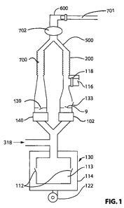
[0005] Figure 1 is a diagram of one embodiment of a breathing circuit
used for conscious or unconscious ventilated patients.
[0006] Figure 2 is a plan view of a one embodiment of the ventilator
bag shown in Figures 1 and 4.
[0007] Figure 3 is a cross-sectional view of the ventilator bag illustrating
detail of the valve shown in Figure 2.
[0008] Figure 4 is a diagram of the breathing circuit showing an
alternate location of the blow-through valve.
CA 02723832 2010-11-08
WO 2009/135294 PCT/CA2009/000588
-3-
DETAILED DESCRIPTION OF PREFERRED EMBODIMENTS
[0009] The following terms are defined as set forth below:
[0010] The term "conditioned gas" is used to refer to a gas, optionally
conditioned ambient air, having at least one of the following properties: it
has
a higher content of oxygen than available ambient air, it is less humid than
available ambient air, it has a lower nitrogen gas content relative to
available
ambient air, it comprises exhaled air of a subject that has been scrubbed of
carbon dioxide. In a preferred embodiment, the conditioned gas is a gas that
has a higher content of oxygen as a result of having been generated by re-
breathing circuit and/or an oxygen concentrator and will optionally have been
dehumidified and/or scrubbed).
[0011] The term "conduit" or "conduit segment" is used broadly to refer
to a fluidly intact (pneumatically efficient, and optionally, though not
necessarily sealably intact) gas pathway and includes without limitation,
tubes
and channels of any type that conduct air from place to place.
[0012] The term "towards"when used to describe gas flow in a conduit
segment (particularly when in operative association with a one way valve) is
used to describe unidirectional flow. It will be appreciated that the location
of
valves including one way valves and points of attachment of conduit
segments may often be dictated by convenience orcertain advantageswhich
are not necessarily critical to the operation of the structure in which they
are
incorporated. Accordingly, precise structural linkages may not be material to
the operation even if specified in a drawing or descriptions of preferred
embodiments of the invention and equivalent arrangements will apparent to
persons skilled in art. The term "operative association" and related terms are
meant to signify that the precise method of association or location can be
variably selected without inventive skill and do not materially affect the
operation of some embodiments of the invention. It will also be appreciated
that portions of the gas circuit may be left outside the body of the
apparatus,
particularly disposable, relatively inexpensive, commonly replaceable and
technologically trivial parts, and connected by the user via a port designated
CA 02723832 2010-11-08
WO 2009/135294 PCT/CA2009/000588
-4-
for such connection, in effect making the port equivalent to those portions of
the gas circuit, if added after and secondary to the essential features of the
apparatus. Persons skilled in the art of working with respiratory apparatus
are
attuned to assembly of these types of circuit elements and will readily
perceive an assembly of parts as the essential apparatus.
[0013] The term "ventilator" includes, without limitation, pressure based
ventilators that provide pressure to the airway of the subject to a certain
preset level (e.g. 25 cm H2O) or range, and volume based ventilators that
control the tidal volume and frequency of the inspiratory flow to the patient.
Ventilators of these types could be used for ventilatory assistance of a type
that does not require rigorous pressure, volume, frequency controls. Avariety
of types of ventilatory assistance are known to those skilled in the art
including CPAP, BiPAP, pressure controlled, volume controlled, pressure
support ventilation, airway pressure release ventilation, inspiratory pause,
inspiratory flow profile, proportional assist ventilation, neurally activated
ventilatory assistance, assist control ventilation etc. The term "ventilator
device" is used broadly to refer to a ventilator and may depending on the
context implicitly exclude the gas reservoir component of such a device.
[0014] The term "oxygenated" means air having an oxygen content
higher than ambient air, optionally having a concentration of at least 40%
oxygen.
[0015] The term "life support apparatus" (or interchangeably "life
support device") as used herein, generally is used to refer to the apparatus
as
whole the name contemplating but not implying patient monitoring functions
that may or may not be limited to respiratory parameters. However, this term
may be used interchangeably with "portable respiratory support apparatus"
and "respiratory support apparatus", among others, in which the primary
functions of respiratory support are highlighted in name.
[0016] The term "fresh gas" generally means gas entering the patient's
breathing circuit that does not contain appreciable amounts of carbon dioxide,
CA 02723832 2010-11-08
WO 2009/135294 PCT/CA2009/000588
-5-
and is usually air or oxygen enriched air, although other components may be
present as well, such as anesthetic agents or the like.
[0017] The term "inspiratory relief valve" means a valve that allows gas,
usually ambient air, into a portion of the conduit assembly that is available
to
the patient to breathe on during an inspiratory cycle in which inspiratory
gas,
usually in the form of a conditioned gas, is temporarily depleted.
[0018] The term "patient airway interface" means a patient interface
such as a mask, nasal tube, endotracheal tube, or tracheotomy tube that is
fluidly connected to a patient airway.
[0019] The term "airway" includes, without limitation, the mouth,
trachea, and nose.
[0020] The term "processing" with reference to machine intelligence
means any handling, merging, sorting or computing of machine readable
information using digital or analog circuitry in a way that it is compatible
with
visual presentation on a screen.
[0021] In one aspect, the portable life support system serves to monitor
the outcome of respiratory treatment parameters and may also serve to
monitor non-treatment parameters of importance to attending medical
personnel such as the patient's ECG, heart rate, temperature and blood
pressure. Device parameters may also be displayed most notably available
battery power and operation modes. Respiratory treatment parameters
measured and displayed by the life support system are detailed below. In a
general aspect, the portable life support system of the invention contemplates
that other forms of treatment and/or monitoring could be provided, measured
and/or displayed. The term "treatment" is used broadly to refer to
ministrations
of any kind, including without limitation provision of respiratory gases,
drugs,
stimuli, signals etc.
[0022] A preferred embodiment of the invention will now be described,
and relates to a portable respiratory support apparatus.
CA 02723832 2010-11-08
WO 2009/135294 PCT/CA2009/000588
-6-
[0023] Referring to Figures 1 and 4, when fresh gas enters the circuit
from the fresh gas inlet port 318 the gas will be directed into a contractible
inspiratory reservoir, optionally in the form of the ventilator bag 113.
During
the inhalation phase the blower 122 draws ambient air through a filter (not
shown) into the system and pressurizes the ventilator bag through the
instrumentality of an inspiratory reservoir contractor, optionally in the form
a
pressurized containment chamber or can 114, thus forcing gas accumulated
in the ventilator 130 to flow towards the user e.g. patient. When the
pressurized gas source, optionally in the form of an air pressure generator,
for
example a blower 122 pressurizes the ventilator can 114, the gas from the
ventilator bag 113 flows through the inspiratory flow sensor 102, through a
one-way (1 cmH2O) inspiratory valve 9 down the (standard 22mm) inspiratory
hose 200, through a Y connector 500 and into the patient interface 600.
Pressure in the can 14 may be measured via pressure transducer (not shown)
and pressure in the inspiratory line may be measured via airway pressure
transducer (not shown).
[0024] In Figures 1 and 4, other parts identified with common numbers
include: endotracheal tube (701), filter (702), extendable expiratory hose
(700), expiratory flow sensor (140), expiratory valve (139), and inspiratory
flow
sensor(102)
[0025] In the event, the patient is being ventilated, for example (by
synchronized intermittent mandatory ventilation (SIMV), Pressure Support or
IMV-Assist Control) and is breathing spontaneously and the patient wishes to
inspire a volume of fresh gas that exceeds the volume provided by the system
during normal operation, the inspiratory relief valve 116 will open,
optionally if
the pressure across the valve is less than -6cmH2O. When the valve opens
ambient air will enter the breathing circuit through the filter 118 and will
provide the additional volume desired by the patient. In the event, the
aforementioned inspiratory valve 116 does not open, because the valve 116
malfunctions, the ventilator blow through valves 112 will open when the
negative pressure on the inspiratory line 115 goes below, for example, -
RECTIFIED SHEET (RULE 91.1)
CA 02723832 2010-11-08
WO 2009/135294 PCT/CA2009/000588
-7-
10cmH2O. When the ventilator blow through valve 112 opens fresh gas from
the ventilator can 113 will be directed in the inspiratory line and available
for
inspiration. Fresh gas will be continuously fed into the ventilator can 114
from
environment through the blower 122.
[0026] In alternative embodiment shown in Figure 4, the blow through
valve 166 is alternatively positioned and opens from the ventilator can 114
into the inspiratory line instead of the bag 113.
[0027] In an alternative embodiment, the inspiratory reservoir 113 could
comprise some other suitable vessel, such as a bellows, instead of a bag. In
summary, noteworthy operational and safety features:
(i) Running the blower 122 during the patient's exhalation the system can
provide an adjustable PEEP between 0-10cmH2O.
(ii) If an inspiratory valve does not open, because the valve malfunctions,
the ventilator blow through valve 112 will open when the negative
pressure on the inspiratory line goes below -10cmH2O. When the
ventilator blow-through valve 112 opens fresh gas from the ventilator
can 114 originating from the blower 122 will be available to the patient
via the inspiratory line.
[0028] As shown in Figure 2, in one embodiment bag 113, optionally
made of urethane, ring 180 may be used to seal the bag to a connector ring
181 which connects to the bag 113 to the valve block (not shown).
Alternatively, ring 180 may be replaced by glue of use of RF/sonic welding.
Sealing ring 182 enables a tight seal to the valve block.
[0029] Figure 3 shows a cross-section through the ventilator bag 113
showing how a force translator, optionally in the form of positional
translator,
for example string 96 (which serves as one example of an actuator for
opening the multifunction valve) interconnects valve flaps 94 which are biased
in closed position by biasing means, optionally in the form of springs 90
which
are held in position by cage 91 which in turn abuts against flange 92. Flange
RECTIFIED SHEET (RULE 91.1)
CA 02723832 2010-11-08
WO 2009/135294 PCT/CA2009/000588
-8-
92 is sealingly attached to the bag when the bag expands to a size which
causes the string 96 to pull on valve flaps 94, a -2.5 cm pressure
differential
relative to the can concentrates the force against the bag over a smaller
surface area (the flaps) and is sufficient to open a valve biased closed by
spring 90 which is which geared to open in the event that the pressure outside
the bag is, for example, 10 cm greater than the pressure in the bag (blow
through valve). In this manner the valves 112 can operate as both blow-
through and expiratory relief valves. Sealing ring 93 is also shown in Figure
3.
[0030] The system may be fitted with a safety pressure relief valve or
pop-off 133 that has, for example, an opening pressure approximately equal
to the maximum desired airway pressure, for example, 60cm H2O. Optional
ranges for ventilation parameters include:
1. Inspired 02 concentrations of 21%to 93% - For increased ease of
use, 3 presets may be settable by the user of 21%, 40%, and 85%. Tidal
volumes may be settable between 400ml and 1 litre (e.g in increments of
100ml), which are useful for adult ventilation.
2. Breath Frequency: between 8 and 20 per minute
3. PEEP: 0-25 cm H2O optionally with settings incremented in 5 cm
H2O
4. Inspiratory: Expiratory ratio between 1:1 AND 1:2 - this is typically
adjusted automatically based on tidal volume, breath frequency, and blower
flow rate.
5. End Inspiratory or end expiratory Pause with pressure hold.
[0031] If the system reaches the maximum airway pressure limit set on
the ventilator control, the blower may stop blowing and may switch into a
constant PEEP mode.
[0032] In spontaneous breathing mode, it is helpful for ease of use to
provide a concentration of 40% 02 , since most adults require less than 8
LPM of FGF, and providing this concentration requires a oxygen source
RECTIFIED SHEET (RULE 91.1)
CA 02723832 2010-11-08
WO 2009/135294 PCT/CA2009/000588
-9-
capable of producing 2.2 LPM of 90% 02 which can be made relatively small
(< 10 lbs.).
[0033] The patient can breathe at any frequency and with any tidal
volume in spontaneous mode.
RECTIFIED SHEET (RULE 91.1)