Note: Descriptions are shown in the official language in which they were submitted.
CA 02723969 2012-09-26
-1-
VEHICLE HAVING A REMOVABLE SUB-PIPE
FIELD OF THE INVENTION
The present invention relates to a vehicle, and in particular, to a vehicle
with
improved mountability of large-sized accessories or vehicle auxiliary
components such as a fuel tank.
BACKGROUND OF THE INVENTION
An arrangement is known in which a large-sized auxiliary component, such as a
fuel tank, is disposed below a rear pipe that supports a seat on which an
occupant sits (see, for example, Japanese Patent Laid-Open No. 2002-248953
(Figs. 3 and 7).
Referring to Fig. 7 of Japanese Patent Laid-Open No. 2002-248953, which is a
perspective view showing a vehicle body frame, left and right upper portion
frame pipes (19) (parenthetic numbers indicate numerals given in Japanese
Patent Laid-Open No. 2002-248953; the same holds true hereinafter) are
extended longitudinally along a vehicle body and have a rear portion supported
by an oblique rear portion support pipe (24).
Referring to Fig. 3 of Japanese Patent Laid-Open No. 2002-248953, the rear
portions of the upper portion frame pipes (19) are referred to as a rear pipe
that
supports a seat (6). A fuel tank (81) is disposed downwardly of the rear pipe.
An oblique member shown downwardly of the fuel tank (81) is the rear portion
support pipe (24) shown in Fig. 7.
The fuel tank (81) is disposed in a space between the rear pipe and the rear
portion support pipe (24), which achieves efficient space utilization.
CA 02723969 2012-09-26
-2-
The fuel tank (81) is mounted in a direction equivalent to a front-and-back
direction of Fig. 3, so that the fuel tank (81) has a height that is smaller
than a
distance between a lower surface of the rear pipe and an upper surface of the
rear portion support pipe (24).
The foregoing structure makes it necessary to lower the rear portion support
pipe (24), if there is a need for increasing the size of the fuel tank (81).
Because of
vehicle structural reasons, however, it is not unlikely that the rear portion
support pipe (24) cannot be lowered.
A need therefore exists for a structure that allows a large fuel tank much
greater
than the distance between the lower surface of the rear pipe and the upper
surface of the rear portion support pipe (24) to be mounted without having to
lower the rear portion support pipe (24). Though the fuel tank has been used
as
an example in the foregoing descriptions, any other accessory or auxiliary
component may be mounted.
It is an object of the present invention to provide a vehicle having a
structure
that allows a large-sized accessory or auxiliary component, such as a fuel
tank,
to be mounted downwardly of a rear pipe without having to lower a rear
portion support pipe.
SUMMARY OF THE INVENTION
The present invention provides a vehicle that includes: at least one main
frame
extending longitudinally along the vehicle; a pair of left and right rear
pipes
extending rearwardly of the vehicle from an upper portion of a rear portion of
the main frame; left and right rear sub-pipes, each rear sub-pipe connecting
between a corresponding rear pipe and the at least one main frame, the rear
sub-
pipes for reinforcing the rear pipes; and a vehicle auxiliary component, such
as a
fuel tank and an air cleaner, disposed rearwardly of the at least one main
frame.
In this vehicle, a first rear sub-pipe of the left and right rear sub-pipes is
fixed to
a first rear pipe of the left and right rear pipes and the at least one main
frame;
and a second rear sub-pipe is removably attached to a second rear pipe and the
at least one main frame.
CA 02723969 2012-09-26
-3-
In the present invention, the first rear sub-pipe of the left and right rear
sub-
pipes (that correspond to the rear portion support pipe of the related art) is
fixed
to the first rear pipe of the left and right rear pipes (that correspond to
the "rear
portions" of the upper portion frame pipes of the related art) and the at
least one
main frame (that corresponds to the upper portion frame pipes of the related
art)
and the second rear sub-pipe is removably attached to the second rear pipe and
the at least one main frame.
A large-sized auxiliary component, such as a fuel tank, can be inserted into a
space under the rear pipe by removing the second rear sub-pipe from the main
frame and the rear pipe. In addition, the auxiliary component is previously
mounted on the second rear sub-pipe and the second rear sub-pipe integrated
with the auxiliary component can thereafter be mounted on the main frame and
the rear pipe.
Specifically, the first aspect of the present invention provides a vehicle
having a
structure that allows a large-sized auxiliary component, such as a fuel tank,
to be
mounted downwardly of the rear pipe without having to lower the rear sub-
pipe.
In an aspect of the invention, the second rear sub-pipe is formed to be
removed
onto an outside in a vehicle width direction and is fastened with bolts from a
side of a vehicle body.
In the above aspect of the invention, the second rear sub-pipe is formed to be
removed onto the outside in the vehicle width direction and is fastened with
bolts from a side of the vehicle body.
The second rear sub-pipe can be fixed to the main frame and the rear pipe by
simply tightening the bolts. Similarly, by simply loosening the bolts, the
second
rear sub-pipe can be removed from the main frame and the rear pipe and the
large-sized auxiliary component can be removed onto the outside in the vehicle
width direction. This facilitates mounting and helps reduce the number of man-
hours involved in mounting the auxiliary component.
CA 02723969 2012-09-26
-4-
In another aspect of the invention, the first rear sub-pipe has a curved
portion
that is curved inwardly in the vehicle width direction so as to be disposed at
a
position closer to a vehicle center side than the first rear pipe in a vehicle
plan
view; and at least one auxiliary component support portion for supporting the
auxiliary component is disposed on such a curved portion.
In the above aspect of the invention, the first rear sub-pipe has the curved
portion that is curved inwardly in the vehicle width direction so as to be
disposed at a position closer to the vehicle center side than the first rear
pipe in a
vehicle plan view; and at least one auxiliary component support portion for
supporting the auxiliary component is disposed on such a curved portion.
The curved portion of the first rear sub-pipe is curved inwardly in the
vehicle
width direction so as to be disposed at a position closer to the vehicle
center side
than the first rear pipe in a vehicle plan view. The first rear sub-pipe can
therefore be viewed in a plan view without being obstructed by the first rear
pipe disposed upwardly of the first rear sub-pipe. Since the auxiliary
component support portion is disposed on the first rear sub-pipe, the bolt can
be
inserted in the auxiliary component support portion from above and tightened.
In a further aspect of the invention, the first rear sub-pipe is mounted with
a first
auxiliary component cover for covering a first side surface of the auxiliary
component; the second rear sub-pipe is mounted with a second auxiliary
component cover for covering at least two surfaces of a second side surface, a
bottom surface, and a rear surface of the auxiliary component; and the first
auxiliary component cover is combined with the second auxiliary component
cover to thereby cover the auxiliary component.
In the above aspect of the invention, the first rear sub-pipe is mounted with
the
first auxiliary component cover for covering the first side surface of the
auxiliary
component; the second rear sub-pipe is mounted with the second auxiliary
component cover for covering at least two surfaces of the second side surface,
the bottom surface, and the rear surface of the auxiliary component; and the
first
auxiliary component cover is combined with the second auxiliary component
cover to thereby cover the auxiliary component.
CA 02723969 2012-09-26
-5-
The auxiliary component is mounted in advance on the second rear sub-pipe
and the second auxiliary component cover is mounted in advance. This allows
mounting of the auxiliary component cover to be completed by simply
mounting the second rear sub-pipe on the main frame and the rear pipe.
Specifically, mounting of the auxiliary component cover is made easy.
In another aspect of the present invention, the auxiliary component is a fuel
tank
and the at least one main frame includes a pair of left and right main frames,
a
cross section extends in the vehicle width direction from a rear portion of
the left
main frame to a rear portion of the right main frame, and the cross section
has a
tank support hole, in which a front portion of the fuel tank is supported; and
a
lug boss extending forwardly of the vehicle from the fuel tank is fitted into
the
tank support hole.
In the above aspect of the invention, the at least one main frame includes a
pair
of left and right main frames, the cross section extends in the vehicle width
direction from the rear portion of the left main frame to the rear portion of
the
right main frame, and the cross section has the tank support hole, in which
the
front portion of the fuel tank is supported; and the lug boss extending
forwardly
of the vehicle from the fuel tank is fitted into the tank support hole.
The front portion of the fuel tank is fixed to the vehicle body side by simply
fitting the lug boss in the tank support hole on the vehicle body side. This
reduces the number of man-hours required for mounting the fuel tank.
In yet another aspect of the invention, an exhaust pipe extending
longitudinally
along the vehicle or a muffler connected to the exhaust pipe is disposed on an
outside in the vehicle width direction of the curved portion.
In the above aspect of the invention, the exhaust pipe extending
longitudinally
along the vehicle or the muffler connected to the exhaust pipe is disposed on
the
outside in the vehicle width direction of the curved portion.
The exhaust pipe or the muffler is often disposed on the outside in the
vehicle
width direction of the rear sub-pipe. In such a case, the exhaust pipe or the
CA 02723969 2012-09-26
-6-
muffler protrudes outwardly in the vehicle width direction to make the vehicle
width greater. In this respect, in the sixth aspect of the present invention,
since
the exhaust pipe or the muffler is disposed on the outside in the vehicle
width
direction of the curved portion that is curved inwardly in the vehicle width
direction, the vehicle width can be inhibited from being increased.
In a further aspect of the invention, a canister for trapping fuel vapor
generated
in the fuel tank is disposed on the first rear pipe at a position closer to
the vehicle
center side than the first auxiliary component cover.
In the above aspect of the invention, the canister for trapping fuel vapor
generated in the fuel tank is disposed on the first rear pipe at a position
closer to
the vehicle center side than the first auxiliary component cover.
Since the canister is disposed on the first rear pipe, there is no likelihood
that the
canister will be removed when the auxiliary component is removed together
with the second rear sub-pipe. Moreover, the canister is covered with the
first
auxiliary component cover. This makes it difficult to remove the canister and
there is no likelihood that the canister will be inadvertently removed.
In addition, if the exhaust pipe or the muffler is disposed downwardly of the
first rear pipe, it results in the canister being disposed near the exhaust
pipe or
the muffler, so that the canister is expected to be heated by heat of the
exhaust
pipe or the muffler and purging efficiency of the canister be enhanced.
BRIEF DESCRIPTION OF THE DRAWINGS
Preferred embodiments of the invention are shown in the drawings, wherein:
Fig. 1 is a side elevational view showing a vehicle according to an embodiment
of the present invention.
CA 02723969 2012-09-26
-7-
Fig. 2 is a plan view showing the vehicle according to the embodiment of the
present invention.
Fig. 3 is a perspective view showing a vehicle body frame.
Fig. 4 is a view on arrow 4 of Fig. 3.
Fig. 5 is a backside perspective view showing the vehicle body frame.
Fig. 6 is an exploded view showing an auxiliary component cover.
Fig. 7 is an assembly drawing of the auxiliary component cover.
Fig. 8 is a rear elevational view showing the vehicle according to the
embodiment of the present invention.
DETAILED DESCRIPTION OF THE PREFERRED EMBODIMENTS
A specific embodiment to which the present invention is applied will be
described below with reference to the accompanying drawings. The drawings
should be viewed in the direction of reference numerals.
An embodiment of the present invention will be described below with reference
to the accompanying drawings.
Referring to Fig. 1, a vehicle 10 is a small-sized vehicle that includes a
front
wheel 11, a front fender 12, a rear wheel 13, a rear fender 14, a steering
handlebar 15, a front luggage deck 16, a seat 17, and a rear luggage deck 18.
Specifically, the front wheel 11 is disposed at a lower portion of a front
portion
of a vehicle body. The front fender 12 is disposed upwardly of the front wheel
11. The rear wheel 13 is disposed at a lower portion of a rear portion of the
vehicle body. The rear fender 14 is disposed upwardly of the rear wheel 13.
The
steering handlebar 15 is disposed upwardly of the front wheel 11. The front
luggage deck 16 is disposed at the front of the steering handlebar 15. The
seat 17
and the rear luggage deck 18 are disposed rearwardly of the steering handlebar
15.
CA 02723969 2012-09-26
-8-
Referring to Fig. 2, the vehicle 10 is a saddle riding type, off-road vehicle
having
left and right step floors 19, 19 between the steering handlebar 15 and the
seat
17. An occupant sitting on the seat 17 can rest his or her feet on the step
floors
19, 19.
A structure of a vehicle body frame that forms a main element of the vehicle
10
described above will be described below.
Referring to Fig. 3, a vehicle body frame 30 includes a pair of left and right
main
frames 31L, 31R (L is a suffix indicating the left as viewed from the occupant
and
R is a suffix indicating the right as viewed from the occupant; the same holds
true hereinafter), left and right front wheel suspension support sections 32L,
32R, a first cross section 33, a second cross section 34, an upper tension
pipe 35, a
pair of left and right rear pipes 36L, 36R, a first rear sub-pipe 37L, and a
second
rear sub-pipe 37R. Specifically, the main frames 31L, 31R extend in a vehicle
longitudinal direction and has rear portions curved upwardly. The front wheel
suspension support sections 32L, 32R are formed of pipes or frames that extend
upwardly from front portions of the main frames 31L, 31R to support a front
wheel suspension system. The first cross section 33 extends in a vehicle width
direction from the left front wheel suspension support section 32L to the
right
front wheel suspension support section 32R. The second cross section 34
extends
in the vehicle width direction from the rear portion of the left main frame
31L to
the rear portion of the right main frame 31R. The upper tension pipe 35 has a
front end removably attached to the first cross section 33 and a rear end
removably attached to the second cross section 34. The rear pipes 36L, 36R
extend rearwardly of the vehicle from upper portions of the rear portions of
the
main frames 31L, 31R. The first rear sub-pipe 37L extends obliquely to the
first
rear pipe 36L from an intermediate portion of the rear portion of the first
main
frame 31L. The second rear sub-pipe 37R extends obliquely to the second rear
pipe 36R from an intermediate portion of the rear portion of the second main
frame 31R. The rear sub-pipes 37L, 37R are reinforcing stays for reinforcing
the
rear pipes 36L, 36R.
The reinforcing stays will be described in more detail.
CA 02723969 2012-09-26
-9-
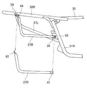
The first rear sub-pipe 37L is welded to the first main frame 31L and the
first
rear pipe 36L.
The second rear sub-pipe 37R is removably fastened to the second main frame
31R and the second rear pipe 36R as shown in Fig. 4 that is a view on arrow 4
of
Fig. 3.
Hence, for example, a front portion stay 38 is extended rearwardly of the
vehicle
from the intermediate portion of the rear portion of the second main frame
31R.
The front portion stay 38 has a surface that can be viewed from a side of the
vehicle.
A rear portion stay 39 is extended downwardly from the rear portion of the
second rear pipe 36R. The rear portion stay 39 has a surface that can be
viewed
from a forward direction of the vehicle.
The second rear sub-pipe 37R having an L-shape is a pipe member that has a
bolt hole 41 penetrating in the vehicle width direction at a front end portion
thereof and a bolt hole 42 penetrating in the vehicle longitudinal direction
at a
rear end portion thereof.
Bolts 43, 44 are passed through the bolt holes 41, 42, respectively, to
thereby
removably attach the second rear sub-pipe 37R to the second main frame 31R
and the second rear pipe 36R.
When the front end of the rear sub-pipe 37R is applied to the surface of the
front
portion stay 38, and when an external force then acts on the rear sub-pipe 37R
in
the vehicle width direction, the external force is removably supported by the
surface of the front portion stay 38 effectively.
Similarly, when the rear end of the rear sub-pipe 37R is applied to a front
surface
of the rear portion stay 39, and when an external force then acts on the rear
sub-
CA 02723969 2012-09-26
-10-
pipe 37R rearwardly of the vehicle, the external force is removably supported
by
the front surface of the rear portion stay 39 effectively.
Shapes of the rear sub-pipes 37L, 37R will be additionally described with
reference to Fig. 5.
Referring to Fig. 5, the right rear sub-pipe 37R has a descent portion
extending
downwardly substantially in parallel with the main frame 31R.
The left rear sub-pipe 37L, on the other hand, is curved so as to bulge
inwardly
in the vehicle width direction (toward a vehicle width center side), which
forms
a curved portion 46. At least one left auxiliary component support portion 47L
is disposed on the curved portion 46 so as to bulge inwardly in the vehicle
width
direction.
A right auxiliary component support portion 47R that assumes a counterpart of
the left auxiliary component support portion 47L is disposed on the right rear
sub-pipe 37R.
The cross section (second cross section 34) that extends from the rear portion
of
the left main frame 31L to the rear portion of the right main frame 31R has a
tank
support hole 48. The tank support hole 48 opens rearwardly of the vehicle.
The auxiliary component will be described below.
The embodiment of the present invention will be described by using a fuel tank
as an example. The type of auxiliary component may nonetheless be any large-
sized onboard part, such as an air cleaner, or a battery or other electrical
part.
Referring to Fig. 6, a first auxiliary component cover 52 that covers a left
side
surface 51 of a fuel tank 50 is mounted on the first rear sub-pipe 37L.
In addition, the fuel tank 50 is a container that has a substantially
rectangular
shape in a plan view and includes a fuel cap 53 and a fuel pump 54. The fuel
tank 50 further includes a lug boss 55 disposed at a front surface thereof,
CA 02723969 2012-09-26
-11-
extending forwardly of the vehicle, and a right flange 56R and a left flange
56L
disposed on a rear surface thereof.
The fuel tank 50 having arrangements as described above is attached to the
second rear sub-pipe 37R in advance by fastening the right flange 56R and the
right auxiliary component support portion (identified by reference numeral 47R
in Fig. 5) with a bolt 57.
At the same time, a second auxiliary component cover 61 that covers a right
side
surface 58, a bottom surface, and a rear surface 59 of the fuel tank 50 is
attached
to the second rear sub-pipe 37R in advance.
Next, referring to Fig. 7, while the lug boss 55 on the side of the fuel tank
50 is
being inserted in the tank support hole 48 on the vehicle body side, the left
flange 56L is placed on the left auxiliary component support portion
(identified
by reference numeral 47L in Fig. 5), and a bolt 62 is inserted from above and
tightened. The fuel tank 50 is now fixed to the vehicle body side at one place
at
the front and two places in the rear, a total of three places.
As a result, the first auxiliary component cover 52 is combined with the
second
auxiliary component cover 61 to be a single complete auxiliary component
cover.
The complete auxiliary component cover covers the bottom surface, the rear
surface 59, the left side surface, and the right side surface 58 of the fuel
tank 50.
In addition, a canister 64 that traps fuel vapor generated in the fuel tank 50
is
mounted on the first rear pipe 36L by a stay 65 at a position closer to the
vehicle
center side than the first auxiliary component cover 52. The fuel vapor
generated in the fuel tank 50 is collected in the canister 64 through a charge
pipe
67 that extends from the fuel tank 50 and connects to a front portion of the
canister 64. The fuel vapor is then sent as appropriately to an intake system
of
an engine through a purge pipe 68 that extends forwardly of the vehicle from
the
front portion of the canister 64. Additionally, a drain pipe 69 extends from a
rear
surface of the canister 64 to be open to atmosphere.
CA 02723969 2012-09-26
-12-
In addition, a fuel supply pipe 71 is routed from the fuel pump 54 along the
right
side of the canister 64 in the vehicle width direction and the right side of
the left
rear pipe 36L in the vehicle width direction toward the engine.
Additionally, referring to Fig. 8, an exhaust pipe extending in the vehicle
longitudinal direction or a muffler 66 connected thereto is disposed on the
outside in the vehicle width direction of the curved portion 46.
Effects of the rear portion structure of the vehicle 10 having arrangements as
described heretofore will be described below.
Referring to Fig. 4, a large-sized auxiliary component, such as the fuel tank,
can
be inserted into a space under the right rear pipe 36R by removing the second
rear sub-pipe 37R from the right main frame 31R and the right rear pipe 36R.
Further, the arrangements permit the following. Specifically, the auxiliary
component 50 is previously mounted on the second rear sub-pipe 37R as shown
in Fig. 6 and the second rear sub-pipe 37R integrated with the auxiliary
component 50 can thereafter be mounted on the right main frame 31R and the
right rear pipe 36R shown in Fig. 4.
Additionally, referring to Fig. 4, the second rear sub-pipe 37R is adapted to
be
removed onto the outside in the vehicle width direction and fastened with the
bolts 43, 44 from a side of the vehicle body.
The second rear sub-pipe 37R can be fixed to the right main frame 31R and the
right rear pipe 36R by simply tightening the bolts 43, 44. Similarly, by
simply
loosening the bolts 43, 44, the second rear sub-pipe 37R can be removed from
the
right main frame 31R and the right rear pipe 36R and the large-sized auxiliary
component can be removed onto the outside in the vehicle width direction. This
facilitates mounting and helps reduce the number of man-hours involved in
mounting the auxiliary component.
CA 02723969 2012-09-26
-13-
Referring to Fig. 5, the first rear sub-pipe 37L includes the curved portion
46 that
is curved inwardly in the vehicle width direction so as to be disposed at a
position closer to the vehicle center side than the first rear pipe 36L in a
vehicle
plan view. At least one left auxiliary component support portion 47L for
supporting the auxiliary component is disposed on this curved portion 46.
The curved portion 46 of the first rear sub-pipe 37L is curved inwardly in the
vehicle width direction so as to be disposed at a position closer to the
vehicle
center side than the first rear pipe 36L in a vehicle plan view. As shown in
Fig.
6, therefore, the first rear sub-pipe 37L can be viewed in a plan view without
being obstructed by the first rear pipe 36L disposed upwardly of the first
rear
sub-pipe 37L. Since the left auxiliary component support portion 47L is
disposed on the first rear sub-pipe 37L, the bolt 62 can be inserted in the
left
auxiliary component support portion 47L from above and tightened as shown in
Fig. 7.
Further, referring to Fig. 4, the first auxiliary component cover 52 that
covers a
first side surface of the auxiliary component 50 is disposed on the first rear
sub-
pipe 37L, and the second auxiliary component cover 61 that covers at least two
surfaces of a second side surface, the bottom surface, and the rear surface of
the
auxiliary component 50 is disposed on the second rear sub-pipe 37R. The first
auxiliary component cover 52 is then combined with the second auxiliary
component cover 61 to cover the auxiliary component 50.
The auxiliary component 50 is mounted in advance on the second rear sub-pipe
37R and the second auxiliary component cover 61 is mounted in advance. This
allows mounting of the auxiliary component cover to be completed by simply
mounting the second rear sub-pipe 37R on the main frame and the rear pipe.
Specifically, mounting of the auxiliary component cover is made easy.
Additionally, referring to Fig. 7, the second cross section 34 that extends in
the
vehicle width direction from the rear portion of the left main frame 31L to
the
rear portion of the right main frame 31R has the tank support hole 48, in
which
the front portion of the fuel tank 50 is supported. It is further arranged
that the
lug boss 55 that extends forwardly of the vehicle from the fuel tank 50 is
fitted in
the tank support hole 48.
CA 02723969 2012-09-26
-14-
The front portion of the fuel tank 50 is fixed to the vehicle body side by
simply
fitting the lug boss 55 in the tank support hole 48 on the vehicle body side.
This
reduces the number of man-hours required for mounting the fuel tank 50.
Additionally, referring to Fig. 8, the exhaust pipe extending in the vehicle
longitudinal direction or the muffler 66 connected thereto is disposed on the
outside in the vehicle width direction of the curved portion 46.
Since the exhaust pipe or the muffler 66 is disposed on the outside in the
vehicle
width direction of the curved portion 46 that is curved inwardly in the
vehicle
width direction, the vehicle width can be inhibited from being increased.
Additionally, referring to Fig. 7, the canister 64 is mounted on the first
rear pipe
36L at a position closer to the vehicle center side than the first auxiliary
component cover 52.
Since the canister 64 is disposed on the first rear pipe 36L, there is no
likelihood
that the canister 64 will be removed when the auxiliary component 50 is
removed together with the second rear sub-pipe 37R.
Moreover, the canister 64 is covered with the first auxiliary component cover
52.
This makes it difficult to remove the canister 64 and there is no likelihood
that
the canister 64 will be inadvertently removed.
Expectedly, the canister 64 will be heated by heat of the exhaust pipe or the
muffler 66 and purging efficiency of the canister 64 will be enhanced.
In the embodiment of the present invention, the "first" is used to denote the
left
element and the "second" is used to denote the right element. Nonetheless, the
"first" may be used to denote the right element and the "second" used to
denote
the left element.
In addition, the three surfaces (the bottom surface, the rear surface, and the
right
side surface) of the fuel tank as the auxiliary component are covered with the
second
CA 02723969 2012-09-26
-15-
auxiliary component cover; however, the rear surface may be omitted as long as
the vehicle body cover can cover the same. Consequently, the second auxiliary
component cover should serve its purpose as long as it can cover at least two
surfaces of the auxiliary component.
The vehicular rear portion structure according to the present invention is
suitable for a small-sized vehicle, in particular, an off-road vehicle. The
structure may still be applied to other types of vehicles.
The vehicular rear portion structure according to the present invention is
suitable for an off-road vehicle.
Although various preferred embodiments of the present invention have been
described herein in detail, it will be appreciated by those skilled in the
art, that
variations may be made thereto without departing from the invention as defined
in the appended claims.