Note: Descriptions are shown in the official language in which they were submitted.
CA 02724148 2010-12-01
TITLE OF THE INVENTION: METHOD AND APPARATUS FOR REMOVING SOLUTE
FROM A SOLID SOLUTE-BEARING PRODUCT
FIELD OF THE INVENTION
The present invention generally relates to a method and apparatus for removing
solute
from solute-bearing solid product, and more particularly to a method and
apparatus for
removing oil from an oil-bearing solid product by means of a solvent that
leaches the oil from
the oil-bearing product.
BACKGROUND OF THE INVENTION
Processes for removing oil from solid oil-bearing products are known in the
art.
Some such processes occur in an extraction chamber where a solvent is sprayed
or otherwise
injected on the oil-bearing product, to leach the oil out of the solid
product. There results a
miscella comprising a mixture of oil and solvent, which is conveyed to an oil-
solvent
separation chamber.
Some processes make use of a liquid solvent which is liquid at given
extraction
temperature and pressure values, but which is normally gazeous at ambient
temperature and
pressure values. After having leached the oil out of the solid product with
the liquid-state
solvent in the extraction chamber, the miscella is separated into its distinct
oil and solvent
components in the separation chamber which is heated to such a temperature
that the solvent
becomes gazeous while the oil remains liquid, thus allowing the oil and
solvent to be easily
distinctly collected.
One problem associated to such prior art processes is that the oil and the
solids will
often be denatured by the application of heat to the solids and/or oil, which
is undesirable.
Denaturing is defined as any physical, chemical or molecular change in the
solute or solid
product. This is especially true, in prior art processes, during the
separation phase of the
miscella, where relatively high oil-denaturing temperatures are often reached.
SUMMARY OF THE INVENTION
One illustrative embodiment relates to a process for separating a solute from
a solute-
bearing solid product comprising the steps of:
1
CA 02724148 2010-12-01
providing an extraction chamber with determined extraction pressure and
temperature
values;
controlling said extraction pressure to maintain it above an ambient pressure
value;
controlling said extraction temperature to maintain it at a temperature that
will not
denature said solute nor said solid product;
feeding said solute-bearing solid product in said extraction chamber;
providing a solvent which is in mainly liquid state at said extraction
pressure and
temperature values, with said solute being soluble in said solvent at said
extraction pressure
and temperature values;
- injecting said solvent in liquid state on said solute-bearing product in
said extraction
chamber for leaching said solute from said solid product with said solvent;
distinctly recuperating said solid product from which at least a portion of
said solute
has been leached, and a miscella comprising a mixture of said solvent and said
solute leached
from said solid product;
- conveying said miscella to a separation unit with determined separation
temperature
and pressure values, with said solvent remaining mainly in liquid state at
said separation
temperature and pressure values, and with said separation unit temperature
value being
controlled to maintain it at a temperature that will not denature said solute;
separating said solvent from said solute in said separation unit through a
liquid-liquid
separation process; and
distinctly recuperating said solvent and said solute separated in said
separation unit;
wherein said solvent remains mainly in a liquid-state throughout said process.
In one embodiment, said solvent is in gazeous state at ambient temperature
and pressure values but mainly in liquid state at said extraction temperature
and pressure
values.
In one embodiment, said extraction and separation temperatures are equal to
ambient temperature, with said solvent being maintained mainly in liquid-state
throughout
said process by means of said extraction and separation pressures being
maintained above
ambient pressure.
3 0 In one embodiment, said solvent recuperated from said separation unit is
re-
utilized within said extraction chamber for extracting additional solute from
additional said
2
CA 02724148 2010-12-01
solute-bearing material, whereby said solvent is used within a closed-loop
circuit and remains
mainly in liquid state throughout said closed-loop circuit.
In one embodiment, said liquid-liquid separation process is one of molecular
weight,
specific gravity and viscosity differential separation processes.
In one embodiment, said process is a batch process, with the step of feeding
said
solute-bearing solid product in said extraction chamber being accomplished by
loading a
batch of solute-bearing solid product in said extraction chamber.
In an alternate embodiment, said process is a continuous process, with the
step of
feeding said solute-bearing solid product in said extraction chamber being
accomplished by
continuously circulating the solute-bearing product through said extraction
chamber and
continuously recuperating solid product from which at least a portion of oil
has been leached
at an outlet of said extraction chamber.
In one embodiment, said extraction chamber comprises a number of extraction
chamber portions through which said solute-bearing product is sequentially
circulated for
extracting solute from the solute-bearing solid product, with each extraction
chamber portion
defining corresponding extraction chamber parameters and with at least some
extraction
chamber parameters differing from one extraction chamber to the other.
In one embodiment, the step of injecting said solvent in said extraction
chamber is
accomplished by means of at least one spray nozzle extending in said
extraction chamber
capable of forming a vortex-shaped solvent spray pattern.
In one embodiment, the step of continuously circulating said solute-bearing
product
through said extraction chamber is accomplished by means of an auger equipped
with
agitation paddles, said process further comprising the step of agitating
particles of said solute-
bearing product to promote the formation of free-floating solid product
particles that will be
at least partly carried into said vortex-shaped solvent spray pattern.
In one embodiment, the step of controlling said extraction pressure to
maintain it
above an ambient pressure value is accomplished by means of a gas injector
injecting in said
extraction chamber one of a vapor of said solvent and a gas which is
unreactive with said
solvent, oil and solid product.
Another illustrative embodiment relates to an apparatus for separating oil
from an oil-
bearing solid product comprising:
3
CA 02724148 2010-12-01
an extraction chamber;
a solvent injector for injecting solvent in said extraction chamber for
leaching oil from
the oil-hearing solid product to form a miscella comprising a mixture of
solvent and oil;
a miscella outlet in said extraction chamber for collecting miscella; and
- a liquid-liquid separation unit linked to said miscella outlet, for
separating the
miscella into its respective oil and solvent components;
wherein solvent injected in said extraction chamber remains mainly in liquid
state to leach oil
from the oil-bearing product to form therewith the miscella, and remains
mainly in liquid
state in said liquid-liquid separation unit.
In one embodiment, the apparatus further comprises:
an inlet valve located upstream of said extraction chamber and allowing said
oil-
bearing solid product to enter said extraction chamber without allowing the
passage of fluid
between said extraction chamber and the atmosphere;
an outlet valve located downstream of said extraction chamber and allowing the
solid
product from which oil has been leached to exit said extraction chamber
without allowing the
passage of fluid between said extraction chamber and the atmosphere; and
an impeller for circulating said solid product from said inlet valve through
said
extraction chamber towards said outlet valve;
wherein said apparatus allows the continuous feeing of solid product to said
inlet valve, the
continuous leaching of oil from the solid product, the continuous output of
solid product from
said outlet valve, and the continuous collection of miscella at said miscella
outlet.
In one embodiment. the apparatus further comprises a security solvent
extraction unit
downstream of said outlet valve, for removing residual solvent vapors by the
application of
heat to the solid product.
Another illustrative embodiment relates to a valve defining an inlet and an
outlet, for
allowing a solid product to pass from said inlet to said outlet while
preventing fluids from
being exchanged between said inlet and outlet, comprising:
an inner channel extending between said inlet and said outlet;
a fluid exhaust port in said inner channel intermediate said inlet and outlet,
said fluid
exhaust port being in communication with a vacuum pump and being equipped with
a filter
allowing passage of fluids through said fluid exhaust port but preventing
passage of the solid
4
CA 02724148 2010-12-01
product through said fluid exhaust port,
a rotary valve member located in said inner channel and being rotatable
therein, said
rotary valve member comprising a main body engaging said inner channel in a
fluid-tight
manner and having an elongated transversal channel, said rotary valve member
being capable
of rotating between a first position in which said transversal channel is
coextensive and
communicates with said valve inner channel and in which said main body
obstructs said fluid
exhaust port, and a second position in which said transversal channel is in
facing register and
communicates with said fluid exhaust port and said main body obstructs said
valve inner
channel; and
- a piston longitudinally movable within said elongated transversal channel
between
two limit positions.
Other aspects and features will become apparent to those ordinarily skilled in
the art
upon review of the following description of illustrative embodiments in
conjunction with the
accompanying figures.
DESCRIPTION OF THE DRAWINGS
In the annexed drawings:
Figure 1 is a schematic view of an apparatus for carrying out an illustrative
embodiment of the present invention according to a continuous process for
removing oil from
an oil-bearing product;
Figure 2 is an enlarged schematic cross-sectional view of the inlet valve of
the
apparatus of figure 1;
Figures 3 to 5 are schematic cross-sectional views of the rotary valve member
only of
the valve of figure 2, at a smaller scale, sequentially showing the rotary
valve member in
three positions thereof and suggesting the rotation of the valve member and
the linear
displacement of the piston with arrows;
Figure 6 is a schematic cross-sectional view of an alternate embodiment of a
valve
assembly according to an illustrative embodiment of the present invention that
includes two
valves similar to the valve of figure 2;
5
CA 02724148 2010-12-01
Figure 7 is a schematic longitudinal cross-sectional view of an extraction
chamber
according to an illustrative embodiment of the present invention;
Figure 8 is a schematic cross-sectional view taken along line VIII-VIII of
figure 7;
and
Figure 9 is a schematic view of an alternate apparatus for carrying out an
illustrative
embodiment of the present invention according to a batch process for removing
oil from an
oil-bearing product.
5A
CA 02724148 2010-12-01
DETAILED DESCRIPTION OF THE EMBODIMENTS
The present invention generally relates to a method and apparatus for
removing a solute from a solute-bearing solid product by means of a solvent
which remains
in liquid state throughout the entire oil extraction process. In one
embodiment, the solvent
is normally in gazeous state at ambient temperature and pressure values, but
is used in liquid
state within the method and apparatus of the present invention by maintaining
such pressure
and temperature values within the apparatus so that the solvent will remain in
this liquid
state. In another embodiment, the solvent is already in liquid state at
ambient temperature
and pressure values, and is maintained in this liquid state within the
apparatus of the
invention.
According to one embodiment of the invention, the solute-bearing product is
a solid product containing a certain quantity of oil or fat. The solid product
can be, for
example, rendered animal tissue, industrial, commercial or domestic oleiferous
wastes,
oleiferous hazards, oleiferous industrial byproducts, oil bearing sands,
strata, mineral, rock
formation, fried or soaked substances inedible and edible, legumes and their
hulls and
casings, seeds and their hulls and casings and/or shells, nuts and their
hulls, casings and/or
shells, tree leafs and branches and roots, plant leafs and stems, basal leafs
and branches and
roots, marine life whether organic, mammal or aquatic, field crops and
vegetables of every
kind, for the separation of the solids from the fats and natural oils
organically, intrinsically
contained, held or suspended by or in them.
The solvent can be any suitable solvent in which said solute will be soluble
at determined extraction pressure and temperature values. In one embodiment,
as indicated
hereinabove, the solvent will be in a gazeous state at ambient temperature and
pressure
values, but will be maintained in a liquid state at extraction pressure and
temperature values.
The solvent may be for example propane or butane mixtures, or a refrigerant.
It is understood that the method and apparatus of the present invention may
be used with many different solvents, the exact nature of the solvent
depending mostly on the
oil-bearing product and the oil contained in the oil-bearing product.
More particularly, the process of the present invention for separating a
solute
from a solute-bearing solid product comprises the steps of-
- providing an extraction chamber with determined extraction pressure and
temperature
6
CA 02724148 2010-12-01
values;
- controlling the extraction pressure to maintain it above an ambient pressure
value;
controlling the extraction temperature to maintain it at a temperature that
will not
denature the solute nor the solid product;
- feeding the solute-bearing solid product in the extraction chamber;
providing a solvent which is mainly in liquid state at the extraction pressure
and
temperature values, with the solute being soluble in the solvent at the
extraction pressure and
temperature values;
injecting the solvent on the solute-bearing in the extraction chamber for
leaching the
solute from the solid product with the solvent;
distinctly recuperating the solid product from which at least a portion of the
solute has
been leached, and a miscella comprising a mixture of the solvent and the
solute leached from
the solid product;
- conveying the miscella to a separation unit with determined separation
temperature
and pressure values, with the solvent remaining mainly in liquid state at the
separation
temperature and pressure values, and with the separation unit temperature
value being
controlled to maintain it at a temperature that will not denature the solute;
separating the solvent from the solute in the separation unit through one of
molecular
weight, specific gravity and viscosity differential separation processes; and
- distinctly recuperating the solvent and the solute separated in the
separation unit;
wherein the solvent remains in a liquid-state throughout said process.
The process of the invention maybe accomplished as a continuous or a batch
process.
Figure 1 is a schematic view of one embodiment of an apparatus 20 used to
carry out the process of the present invention as a continuous process.
Apparatus 20 comprises a feedstock inlet valve 22 connected to a number of
consecutively contiguous extraction chambers 24a, 24b, 24c, 24d, 24e,
generally referred to
as extraction chambers 24, that are in fact extraction chamber portions part
of a single
extraction chamber, as further detailed hereinafter, since they are in fluid
communication
with one another. However, in an alternate embodiment which is not
illustrated, extraction
chamber 24 could be fluidly isolated by suitable valves.
7
CA 02724148 2010-12-01
Downstream of extractions chambers 24 is a solid product outlet valve 26
connected to an optional security solvent extraction unit 28. Oil-bearing
product, or
feedstock, which is to be treated by apparatus 20 to distinctly recuperate the
oil and the solid
product therefrom, is consequently fed through the feedstock inlet valve 22
and sequentially
circulated through the consecutively contiguous extractions chambers 24 where
a determined
proportion of oil will be extracted from the solid oil-bearing product, as
detailed hereinafter.
The solid product from which the oil has been extracted is then conveyed
through solid
product outlet valve 26, towards the outlet of apparatus 20 downstream of
security solvent
extraction unit 28.
Inlet and outlet valves 22, 26 are valves that allow a continuous or
substantially continuous through-flow of solid product, while preventing the
through-flow
of other fluids. Thus, the solid product may freely flow through valves 22,
26, while there
will be no fluid exchange between extraction chambers 24 and the atmosphere.
In one embodiment, to facilitate the treatment of the solid oil-bearing
product,
the solid product is fed through inlet valve 22 in a granular or pellet
format, with the
maximum particle size of the solid product being empirically selected and/or
calculated for
an optimized oil yield.
Determined extraction pressure and temperature values are set and maintained
within extraction chambers 24. More particularly, the extraction pressure is
controlled to
maintain it above ambient pressure value, and the extraction temperature is
controlled to
maintain it at a temperature that will not denature the oil or the solid oil-
bearing product.
These extraction temperature and pressure values are set to allow the solvent
to be
maintained in a liquid state within extraction chambers 24, while in one
embodiment, this
same solvent would be in a gazeous state at ambient temperature and pressure
values. For
example, the extraction temperature can be substantially equal to ambient
temperature, for
example between 1 C (33 F) and 40 C (104 F), and the extraction pressure can
be
maintained well above the ambient pressure value, for example at approximately
10 bars.
However, these exemplary extraction temperature and pressure values are not to
be
considered restrictive, as they may vary depending on the nature of the oil,
the oil-bearing
product and the solvent being used. Still, maintaining an ambient temperature
value within
extraction chambers 24 has the advantage of helping to prevent most oils and
solid products
8
CA 02724148 2010-12-01
form being denatured, since they would naturally be found at ambient
temperature anyway.
One way to maintain the extraction pressure above the ambient pressure, is
to have a gas injector pump 29a connected to a gas injector 29 which injects
gas into
extraction chambers 24. Figure 1 shows a single gas injector 29 for all
extraction chambers
24, but it is understood that multiple gas injectors could be provided. The
nature of the gas
being injected will be discussed hereinafter.
A closed loop liquid solvent circuit is provided within apparatus 20, in which
liquid-state solvent is circulated for use in extracting the oil from the oil-
bearing product fed
into extraction chambers 24. More particularly, a main solvent tank 30 is
provided in
apparatus 20, within which solvent is stored at such temperature and pressure
values so as
to remain mainly in liquid state. A solvent pump 32 conveys solvent from main
solvent tank
30 to a solvent manifold 34, the latter connected to solvent injectors in the
form of a number
of independently controlled spray nozzles 36a, 36b, 36c, 36d, 36e - generally
referred to as
spray nozzles 36 - that will inject solvent in corresponding extraction
chambers 24.
Since the solute is soluble in the solvent at the extraction pressure and
temperature values, as the solvent is sprayed into extraction chambers 24, it
leaches oil from
the solid oil-bearing product, with the solvent and oil forming a miscella
that is recuperated,
for example through a filter (not shown in figure 1) that will prevent the
solid product
particles from flowing therethrough, while allowing the miscella to flow
therethrough. The
miscella is collected through corresponding miscella outlet channels 38a, 38b,
38c, 38d, 38e
- generally referred to as miscella outlet channels 38. Miscella pumps 40a,
40b, 40c, 40d,
40e - generally referred to as miscella pumps 40, are connected to miscella
channels 38 to
ensure an outflow of the miscella from extraction chambers 24. Miscella thus
recuperated
is conveyed to a miscella collection tank 42. Although a single miscella tank
has been
shown, it is understood that distinct miscella tanks corresponding to each
extraction chamber
could also be used. A pump 44 conveys the miscella from miscella tank 42
through a
particulate filter 46 and into a separation unit 48 where the oil is separated
from the liquid-
state solvent through a known liquid-liquid separation process, for example
one of molecular
weight, specific gravity and viscosity differential separation processes.
Also, determined
separation temperature and pressure values are maintained within separation
unit 48, with the
solvent remaining mainly in liquid state at the separation temperature and
pressure values,
9
CA 02724148 2010-12-01
and with the separation unit temperature value being controlled to maintain it
at a
temperature that will not denature the oil. In one embodiment, the separation
temperature
and pressure values are identical to the extraction temperature and pressure
values, for
example approximately ambient temperature and 10 bars, respectively.
The solvent separated from the oil in separator unit 48 is then conveyed by
means of a pump 50 back into main solvent tank 30, while the oil separated
from the solvent
is collected at an oil outlet, after having passed through an optional
segregation unit 52 that
will remove any remaining residual solvent vapors, if any.
Throughout the closed-loop solvent circuit, the solvent remains mainly in
liquid state at all times. In the present specification and claims, although
it is indicated that
the solvent remains in liquid state, it is understood that some liquid-state
solvent will in fact
evaporate unless the corresponding surrounding area within apparatus 20 is
saturated with
solvent vapor - thus in any case some solvent vapor will in fact be present.
The solvent will
not be entirely in liquid state at all times within apparatus 20.
Consequently, when it is stated
that the solvent remains in liquid-state, it refers to the active solvent that
will be injected
through injectors 36, leach the oil from the solid product, form a miscella
with the oil, be
carried to be separated in liquid state in separation unit 48, and then re-
used to be injected
through injectors 36. Thus, apart from a proportion of solvent that will
naturally evaporate
in non-saturated areas of apparatus 20, it can be said that the solvent will
remain "mainly"
in liquid state.
Maintaining the closed-loop solvent circuit in liquid state may be
accomplished for example by maintaining the temperature constant at
approximately an
ambient temperature value and by maintaining an above-ambient pressure value
within the
closed-loop solvent circuit. This is particularly advantageous since it will
help prevent the
2S oil and the solid product circulated within apparatus 20 from being
denatured since they will
not be subjected to a considerable amount of heat which is frequent in prior
art devices.
In a normal operation mode of apparatus 20, most if not all the liquid-state
solvent will be recuperated through the miscella within extraction chambers
24. However,
there may be some cases where the solvent is not entirely removed from the
solid product
when it exits extraction chambers 24, especially some solvent vapors which are
resident in
the extraction chambers 24 and that remain trapped in the solid product. Thus,
optional
CA 02724148 2010-12-01
security solvent extraction unit 28 which is located downstream of outlet
valve 26 is used to
remove the residual solvent in the solid product by the application of heat to
prevent solvent
from accidentally exiting apparatus 20. This heat level is relatively low, in
that the
temperature in the optional security solvent extraction unit 28 will be well
below a
temperature that could denature the solid product processed therein.
If solvent is removed from the solid product in security solvent extraction
unit
28, it may be recuperated, liquefied and conveyed to main solvent tank 30 by
means of
suitable pipes (not shown). The same is true about solvent vapors recuperated
in segregation
unit 52. In cases where there is a net loss of least part of the solvent
during the oil extraction
process of the present invention, then an auxiliary solvent tank 55 equipped
with its pump
55a can be included in apparatus 20 to provide the required additional solvent
to be
distributed by manifold 34.
Alternatively, solvent vapor recuperated in security solvent extraction unit
28
can be conveyed to gas injector 29 to be re-used for maintaining the above-
ambient pressure
within extraction chambers 24. Indeed, it is possible to have solvent vapor-
filled extraction
chambers 24 which allows the desired pressure to be maintained therein. This
does not
change the fact that the solvent injected in liquid-state in extraction
chambers 24 to leach the
oil out of the solid product, will remain mainly in liquid state throughout
the process of the
present invention. Indeed, the solvent vapor is used to maintain the required
pressure, and
although a natural exchange between the gazeous-state solvent and the liquid-
state solvent
will occur, the liquid-state solvent mainly remains in its liquid state.
Alternately, if solvent
vapor is not used to set and maintain the above-ambient pressure in extraction
chambers 24,
then another gas can be used in gas injector 29 that will not react with the
oil, the solvent or
the solid product, for example an inert gas or another unreactive gas such as
nitrogen.
An optional heating device 53 is provided between extraction chambers 24
and outlet valve 26. Heating device 53 is equipped with heating means, for
example in the
form of a heating element 53a, for slightly heating the solid product before
it is submitted to
a sensor device 51 that detects the oil content in the outputted solid
product. This detection
of oil content may help the operator to properly set the extraction chamber
parameters for
obtaining a desired oil content in the solid product at the outlet of
apparatus 20. Known
sensors such as sensor 51 work optimally at a constant temperature, and the
purpose of
11
CA 02724148 2010-12-01
heating element 53 is consequently to maintain the solid product at this
constant temperature.
In one embodiment, shown in figure 1, inlet and outlet valves 22, 26 are each
connected to a vacuum pump 54 and to a compressor 56 that provide appropriate
pressure
differentials required to (a) prevent gases and fluids from the atmosphere
outside of apparatus
20 (e.g. air) from seeping within extraction chambers 24, and (b) prevent
gases and fluids
from inside apparatus 20 (e.g. solvent vapors) from seeping outside of
apparatus 20 through
valves 22, 26. Valves 22, 26 more particularly include an intermediate chamber
in which a
vacuum will be created to remove all fluids therein such as air, before
allowing the solid
products to be conveyed downstream. Since there is a positive pressure within
extraction
chambers 24, compressor 56 will further act to pump gas back into valves 22,
26. Some
particular embodiments of valves 22, 26 will now be discussed, although it is
understood that
the present invention is not limited thereto.
Figure 2 shows a first embodiment of an inlet valve 22. Although valve 26
will not be described in detail, it is understood that valve 26 would be
similar to valve 22.
In the embodiment of figure 2, inlet valve 22 comprises a hollow housing 200
comprising
an inner channel 202 defining a feedstock inlet opening 204 opened to the
ambient
environment, a feedstock outlet opening 206 leading to extraction chambers 24
and a
feedstock flow axis extending between inlet and outlet openings 204, 206. An
auger 208 is
provided at inlet opening 204. Inlet opening maybe located at the bottom end
of a hopper
at least partly filled with feedstock.
Housing 200 also comprises a widened intermediate portion 210 defining a
cylindrical inner channel portion 212 in which a complementary cylindrical
rotary valve
member 214 is rotatable about a rotation axis which is perpendicular to the
feedstock flow
axis. Rotary valve member 214 defines a main body 215 that engages the valve
inner channel
202 in a fluid-tight manner. Rotary valve member 214 comprises a transversal
channel 216
in which a piston 218 is longitudinally movable between first and second limit
positions
corresponding to the two extremities of the rotary valve member transversal
charnel 216.
An air exhaust port 220, equipped with a solid material filter 222 that allows
fluids to pass while preventing solids to pass, is provided on one side of the
housing
intermediate portion 210, being angularly spaced from the valve inner channel
202 at a 90
angle to the right-hand side of figure 2. Air exhaust port 220 is connected to
a selectively
12
CA 02724148 2010-12-01
activated vacuum pump (number 54 in figure 1) through a vacuum channel 224,
and a gas
channel 226 in turn connected to a gas source (number 56 in figure 1) is also
in
communication with air exhaust port 220. The gas circulating through gas
channel 226 may
be solvent vapor, or any other suitable gas, such as nitrogen for example,
which would not
chemically react with the solvent, the oil or the solid product.
A solvent exhaust port 228 equipped with a solid material filter 230 that
allows fluids to pass while preventing solids to pass, is provided on the side
of housing
intermediate portion 210 opposite air exhaust port relative to valve inner
channel 202 -
namely the left-hand side in figure 2. Solvent exhaust port 228 is thus
angularly spaced from
the valve inner channel 202 of a 90 angle and from the air exhaust port of a
180 angle.
Solvent exhaust port 228 is connected to a selectively activated vacuum pump
(number 54
in figure 1) through a vacuum channel 232, and to an air channel 234 which is
connected to
the outside atmosphere.
In use, valve 22 is initially in a position as shown in figure 2, with rotary
valve
member 214 positioned so that transversal channel 216 is coextensive with
valve inner
channel 202, and with piston 218 being located in a first limit position at or
near the
extremity of transversal channel 216 which is closest to feedstock inlet
opening 204. In this
position of rotary valve 214, piston 218 is continuously biased towards its
first limit position
due to the above-ambient pressure within extraction chambers 24.
Feedstock, for example in the form of granular solid oil-bearing material, can
then be forced by auger 208 and by the force of gravity, down into the
feedstock inlet opening
204 of valve 22. As feedstock is gradually fed therein, piston 218 will
gradually be forced
towards its second limit position, against the bias of the pressure within
extraction chambers
24. Eventually, piston 218 will reach its second limit position as shown in
figure 3.
At this point, rotary valve member 214 is rotated of 90 clockwise as shown
in figure 4, until the open end of transversal channel 216, i.e. the end of
transversal channel
216 that is not obstructed by piston 218, comes in facing register with air
exhaust port 220.
A vacuum is then created in exhaust port 220 and consequently in transversal
channel 216,
to purge fluids from transversal chamber 216 by sucking all fluids out of
transversal channel
216 through vacuum channel 224. Solids are retained in transversal channel 216
by filter
222. This consequently removes all air from within the feedstock-filled
transversal channel
13
CA 02724148 2010-12-01
216 to prevent any air from being subsequently allowed into extraction
chambers 24. Once
the vacuum is obtained, the vacuum pump is stopped and gas such as solvent
vapor is
injected into transversal chamber through gas channel 226, until the pressure
within
transversal channel 216 becomes substantially equal to that within extraction
chambers 24.
Once this is accomplished, rotary valve member 214 is rotated a second time
in the same clockwise direction of 90 as shown in figure 5, until the open
end of transversal
channel 216 comes in facing register with the feedstock outlet opening 206 of
valve 22.
Under the force of gravity, and under piston 218 being pushed downward as new
feedstock
is fed through feedstock inlet opening 204 by auger 208, the feedstock present
in transversal
channel 216 will be forced out and through feedstock outlet opening 206.
It is noted that when rotary valve member 214 moves into a position in which
its open end comes in facing register with the air exhaust port as shown in
figure 4, its closed
end, i.e. its end which is obstructed by piston 218, then simultaneously comes
in facing
register with solvent exhaust port 228. A vacuum is then created through
vacuum channel
232 to purge all solvent which may be present in the small area at the very
extremity of
transversal channel provided that piston 218 might not be located exactly at
its second limit
position and that such a small area may consequently exist. Gas exhaust port
228 thus helps
prevent any accidental gas flow out of valve 22. It is noted to this effect
that although piston
218 has been shown with flat opposite top and bottom surfaces, it can be made
with convex
opposite top and bottom surfaces that have a same radius of curvature as that
of the outer
surface of rotary valve member 214. Once the vacuum pump stops purging fluids
through
vacuum channel 232, air at atmospheric pressure is injected through air
channel 234 to fill
the void left by the previously purged fluids. Thus, as the rotary valve
member is rotated
another 90 , all solvent that might have been present between piston 218 and
the housing
inner wall, will have been previously purged, to prevent solvent from being
accidentally
exhausted to the atmosphere.
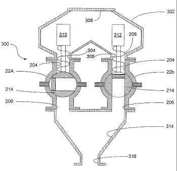
Figure 6 shows another embodiment of a valve assembly 300 according to the
present invention, which comprises a pair of valves 22a, 22b similar to valve
22 described
hereinabove. A hopper 302 is installed atop valves 22a, 22b, and a pair of
tapered bottom
openings 304, 306 in hopper 302 provide access to the respective feedstock
inlet openings
204, 204 of the valves 22a, 22b. A removable cover 308 allows access to the
inner chamber
14
CA 02724148 2010-12-01
of hopper 302. A pair of motors 310, 312 control the augers 208, 208 of valves
22a, 22b. The
respective feedstock outlet openings 206, 206 of valves 22a, 22b open into a
funnel 314
having a funnel outlet opening 316 leading to the extraction chambers 24 (not
shown in
figure 6).
In use, valves 22a, 22b work in a similar manner than valve 22 described
hereinabove. Feedstock located in hopper 302 is gradually fed simultaneously
to both valves
22a, 22b through their respective feedstock inlet openings 204, 204. The
feedstock is
discharged at the respective outlet openings 306, 306 of valves 22a, 22b as
described
hereinabove for valve 22, and funnel 314 directs the incoming feedstock
towards the entrance
to the extraction chambers 24 (not shown in figure 6).
In one embodiment, valves 22a, 22b will have regular cycles which are offset
relative to each other. More particularly, their respective rotary valve
members 214, 214 will
be controlled so as to be angularly offset of 90 at all times, thus allowing
an alternative
feedstock discharge from one valve 22a, then the other 22b.
In the embodiment of the invention illustrated in figure 1, there are shown
five
sequentially linked extraction chambers 24a, 24b, 24c, 24d, 24e. The feedstock
is conveyed
to extraction chambers 24 after having been fed through inlet valve 22, is
destined to be
conveyed in a continuous manner sequentially through all five of the
extraction chambers 24,
namely first through extraction chamber 24a, then through extraction chamber
24b, and so
on until it reaches extraction chamber 24e, after which it is conveyed outside
of the extraction
chamber assembly towards heating chamber 53.
Conveying means for conveying the solid product sequentially along the
extraction chambers 24 are provided, for example in the form of a single
impeller that
extends throughout the entire extraction chamber assembly.
Within each extraction chamber 24, solvent is dispensed according to
determined extraction chamber solvent injection parameters. More generally,
extraction
chambers 24 have determined extraction chamber parameters that will influence
the oil
extraction process therein. These extraction chamber parameters are set
according to each
oil-bearing solid product being treated, according to the oil to be collected
from the solid
product, and according to the solvent being used. These parameters can further
be modified
from one extraction chamber 24 to the other if different extraction chamber
parameters are
CA 02724148 2010-12-01
desired in different extraction chambers 24. Parameters which can be modified
include, but
are not limited to: type of impeller used, including its geometry; rotation
speed of impeller
if it is a rotatable impeller such as an auger; size of extraction chamber;
flow rate of solvent
being dispensed in the extraction chamber 24; flow rate of miscella flowing
out of the
extraction chamber 24; manner of dispensing the solvent, such as by providing
particular
solvent spray patterns; etc...
The purpose of controlling these parameters is to calibrate the oil leaching
process within each extraction chamber 24, and consequently the entire oil
leaching process
throughout the extraction chamber assembly. Indeed, it will often be desirable
to meet
certain specific and relatively precise oil recuperation parameters in the end
product at the
apparatus outlet, for example so as to maximize the oil recuperation or to
reach determined
oil proportions within the outputted solid product.
Figures 7 and 8 show one embodiment of an extraction chamber 24, which
defines opposite upstream and downstream ends 400 and 402, respectively, and
which
comprises a hollow housing 404 defining an inner extraction channel 406
extending between
the extraction chamber upstream and downstream ends 400, 402. The downstream
end 402
of each extraction chamber 24 is in fluid communication with the upstream end
400 of the
sequentially adjacent extraction chamber 24, until the last extraction chamber
24e which
communicates with heating chamber 53. Thus, same extraction pressure and
temperature
values maybe maintained throughout extraction chambers 24. A power-driven
impeller in
the form of an auger 408 extends through inner channel 406, with auger 408
extending
through the entire extraction chamber assembly, from inlet valve 22 to outlet
valve 26,
including through heating chamber 53. Auger 408 also comprises a number of
agitation
paddles 410 integrally attached thereto in designated areas of extraction
chamber 24. Spray
nozzles 36, connected to manifold 34, extend within inner channel 406.
In the embodiment shown in figures 7 and 8, the particles of solid product are
conveyed and agitated by auger 408 and are further agitated by agitation
paddles 410 in a first
portion of each extraction chamber 24 so as to imbue a free-floating product
particles flow
pattern configuration, for example according to the pattern shown in dotted
lines at reference
number 412 in figure 8. Simultaneously, spray nozzles 36 will inject solvent
in such a
manner as to imbue the injected solvent with a vortex spray pattern
configuration, for
16
CA 02724148 2010-12-01
example according to the spray pattern schematically shown in dotted lines at
reference
number 414 in figure 8. This solvent vortex pattern will carry some free-
floating solid
product particles in the vortex, which will enhance the effect of the solvent
on the solid
product particles, thus enhancing the leaching of oil.
Other alternate solvent injection means could also be envisioned by which
solvent is injected in the extraction chambers to leach the oil from the solid
products being
circulated therein.
The solvent thus injected in extraction chamber 24 will leach a certain
proportion of the oil from the oil-bearing product, to form a miscella defined
as a mixture of
solvent and oil.
Downstream of spray nozzles 36 in extraction chamber 24, is provided a
miscella collection trough 416 underneath a filter 418. The miscella, carried
by impeller 408,
will flow and be collected in trough 416, with the solid product particles
being retained by
filter 418 within channel 406. It is understood that a suitable filter will be
selected according
to the type of solvent being used, the type of oil being collected, and the
type of solid product
being processed. The miscella collected in trough 416 will be carried away
through a
corresponding miscella outlet channel 38 (figure 1) communicating with trough
416.
Extraction chamber 24 consequently defines two different operative portions,
namely a first solvent injection portion where solvent is injected in the
agitated solid material
particles, and a second miscella collecting portion where miscella is
collected. Agitation
paddles 410 and spray nozzles 36 are present only in the solvent injection
portion, and filter
418 and trough 416 are present only in the miscella collecting portion.
According to the invention, it can thus be seen that there is provided a
continuous process for extracting oil from an oil-bearing solid product, by
which the solid
2S product is continuously fed through inlet valve 22, continuously circulated
through extraction
chambers 24, and continuously collected at outlet valve 26. Simultaneously, in
each
extraction chamber 24, a certain proportion of oil is continuously extracted
from the oil-
bearing product, whereby a final proportion of oil is extracted at the outlet
of the entire
extraction chamber assembly. It is envisioned, according to one embodiment, to
provide
suitable sensors of known construction (not shown), similar to sensor 51, to
detect the
proportion of oil remaining in the solid product at the outlet of each
extraction chamber 24,
17
CA 02724148 2010-12-01
and to use a control mechanism (not shown) to dynamically control the
extraction chamber
parameters in each extraction chamber 24 so as to obtain a desired remaining
oil proportion
in the solid products at the outlet of apparatus 20. For example, if it is
predetermined that
50%, 90% or even 100% of the oil is to be recuperated from the solid product,
then the
control mechanism could dynamically control distinctly in each extraction
chamber 24 the
solvent flow rate, the solvent spray pattern configuration, the rotation speed
of the impelling
auger, and any other extraction chamber parameter, to modify the oil
extraction parameters
to obtain the desired result according to the oil proportion detected at the
outlet of each
extraction chamber 24.
According to the present invention, the series of extraction chambers 24
through which the solid product is sequentially conveyed will allow for up to
a very
important proportion (if desired), if not all, of the oil to be extracted from
the solid product.
Indeed, each pass of the solid product through one extraction chamber 24
allows oil to be
leached out of the solid product, and consequently providing a series of
extraction chambers
24 allows the proportion of oil in the solid product to inversely
exponentially tend towards
zero, and even eventually reach zero. This oil extraction may also be
calibrated by means of
the dynamic control over oil extraction within the extraction chambers as
described above.
Indeed, contrarily to the prior art known to applicant, the present invention
makes use of a
process for extracting oil in which the extraction chamber parameters may be
modified during
the operation of apparatus 20 according to the results that are detected by
the sensors, either
at the apparatus outlet, and/or at the outlet of every individual extraction
chamber 24. By
dynamically controlling and eventually modifying the extraction chamber
parameters such
as the solvent spray patterns and flow rate and the impeller speed, for
example, the proportion
of oil extraction may thus be selectively controlled.
In addition to relying on the sequence of extraction chambers, the selective
proportion of oil extraction also relies on the manner by which the oil is
extracted within each
extraction chamber. Indeed, not only can the extraction chamber parameters be
dynamically
modified, but the particular agitation of the solid product particles within
each extraction
chamber 24, together with the vortexes of solvent being created by spray
nozzles 36 in each
extraction chamber 24, provide for the possibility of a high extraction rate
in each extraction
chamber 24.
18
CA 02724148 2010-12-01
It is understood that a high extraction rate is only referred to herein as a
choice
or possibility for the operator of apparatus 20. Indeed, while in some cases
maximum oil
extraction may be desirable such as in the case of soil decontamination, in
other cases such
as in the preparation of foodstuff a certain proportion of oil content in the
outputted solid
product may be desirable.
Having an extraction pressure above ambient pressure, for example at
approximately 10 bars, is advantageous not only because it allows the use of a
solvent in
liquid state which would normally be in gazeous state at ambient pressure, for
a given
temperature value, but also because it increases the efficiency of the
process. Indeed, filters
418 with a finer mesh may be used through which the miscella will be
transferred, if the
extraction pressure is important, to promote the passage of miscella through
the filters 418.
It is noted that the respective separation pressure and extraction pressure
within separation unit 48 and extraction chambers 24 respectively, may differ.
An alternate embodiment of the invention is shown in figure 9, where a batch
process apparatus 500 is schematically shown. Apparatus 500 comprises an
extraction
chamber 502 including a feedstock inlet 504, which can be closed by a door
(not shown) once
feedstock is fed into extraction chamber 502. Extraction chamber 502 includes
a first coarse
filter 506, and an outlet 508 leading to a second fine filter 510. In use, a
batch of feedstock
comprising solid oil-bearing product is fed through feedstock inlet 504, the
door to the
extraction chamber 502 is then closed, and the batch oil extraction process
can then begin.
For the oil extraction to be accomplished, solvent from a main solvent tank
512 is injected into extraction chamber 502 by means of a solvent injection
pump 514.
Solvent thus injected leaches a certain proportion of the oil from the oil-
bearing product to
form a miscella comprising a mixture of oil and solvent. The miscella is
collected through
the coarse filter 506 while the coarse solid product particles are retained in
extraction
chamber 502, and then through fine filter 510 while fine particulate solid
product is retained
by fine filter 510. The miscella thus collected is conveyed to a liquid-liquid
separation unit
516 where the oil is separated from the solvent through a suitable liquid-
liquid separation
process such as one of molecular weight, specific gravity and viscosity
differential separation
processes. Solvent separated from the oil is conveyed back to main solvent
tank 512, while
oil separated from the solvent is collected at an oil outlet 518.
19
CA 02724148 2010-12-01
There is also provided a solvent vapor circuit 520 including a solvent vapor
pump 522 that will convey residual solvent vapor from extraction chamber 502
to carry the
solvent back into solvent tank 512 where it will precipitate into liquid
state, once a batch of
solid material has been treated. This prevents solvent vapor from being
exhausted to the
atmosphere once the door to the extraction chamber 502 is opened to remove the
solid
product from therein.
In the embodiment of figure 9, the pressure and temperature values are also
controlled in extraction chamber 502 and in main solvent tank 512 to maintain
the solvent
mainly in liquid state throughout the closed-loop circuit of the solvent. Any
solvent vapor
conveyed by pump 522 back into tank 512 is subjected to temperature and
pressure
conditions that will make the solvent vapor precipitate. As with the first
embodiment
showing a continuous process, the solvent remaining mainly in liquid-state
throughout its
closed-loop circuit prevents any heat from having to be used to separate the
oil from the
solvent by evaporating the solvent. This absence of heat helps prevent
denaturing of the oil.
Any further modification to the present invention, which does not deviate
from the scope of the appended claims as will be obvious for a person skilled
in the art, is
further considered to be included herein.