Note: Descriptions are shown in the official language in which they were submitted.
CA 02724274 2010-11-12
WO 2009/140267 PCT/US2009/043610
PRINTABLE FORM HAVING DURABLE RESISTANT WRISTBAND AND LABELS
DESCRIPTION
BACKGROUND OF THE INVENTION
[Para 1] Form based wristbands, labels and/or tags for identification have
been
known in the prior art. Such identification forms have heretofore been made
using
standard paper label media as the top layer that receives identification
information. The ability of these standard paper label media to resist fluids
has
been found to be inadequate for many applications. For example, in hospitals
or
settings involving exposure to fluids. Such inadequacy has previously been
addressed by providing a lamination layer in addition to the printable media
layer
wherein the lamination layer is foldable over the media layer to protect the
same
from fluids. The addition of this lamination layer creates manufacturing and
design
issues such as increased cost, increased complexity, and increased user
difficulty
in properly aligning or sealing the lamination layer of the printable media
layer.
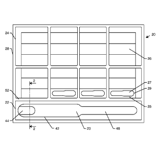
[Para 2] Accordingly, there is a need for a durable wristband that along with
an
array of labels and/or tags can be printed on a standard printer without the
need
for a foldable lamination layer. In addition to being durable, the media layer
should be solvent resistant and involve low cost, ease of manufacture, and
ease of
use. The present invention fulfills these needs and provides other related
advantages.
1
CA 02724274 2010-11-12
WO 2009/140267 PCT/US2009/043610
SUMMARY OF THE INVENTION
[Para 3] The present invention is directed to a printable identification
medium.
The identification medium preferably comprises at least one of a wristband, a
label, a tag, or a sheet including a combination of a wristband, a label or a
tag. In
any of these forms the printable identification medium is configured for
passing
through a standard printer, i.e., laser printer, inkjet printer, thermal
printer,
electro-photography printer, or standard office printer.
[Para 4] The medium includes a polymeric substrate preferably made from
polyethylene terephthalate (PET). A printable media layer is disposed adjacent
to
the polymeric substrate. The printable media layer preferably includes a core
layer, an image receiving layer on a first side of the core layer, and an
adhesive
layer on an opposite second side of the core layer for bonding the printable
media
layer to the polymeric substrate. A release layer is preferably disposed
between a
portion of the adhesive layer and the polymeric substrate as discussed below.
[Para 5] The media layer preferably includes a wristband region, a label
region, a
tag region, or a combination thereof. Die cuts through both the printable
media
layer and polymeric substrate define a wristband within the wristband region.
Die
cuts through the printable media layer and polymeric substrate define a tag
within
the tag region. Die cuts through only the printable media layer define a label
in
the label region. An interior die cut within the defined wristband defines an
attachment portion, wherein the interior die cut is only through the
substrate. An
interior die cut within the defined tag defines a tag attachment portion,
wherein
the interior die cut is only through the substrate.
2
CA 02724274 2010-11-12
WO 2009/140267 PCT/US2009/043610
[Para 6] In the label region, the core layer preferably comprises cellulose
paper or
synthetic paper. In the wristband and/or tag regions, the core layer
preferably
comprises a polymer. The image receiving layer preferably comprises urethane,
polyethylene, polyethylene terephthalate (PET), vinyl, polyolefin, low-density
polyethylene (LDPE), or high-density polyethylene (HDPE), each having a
filler.
[Para 7] Other features and advantages of the present invention will become
apparent from the following more detailed description, taken in conjunction
with
the accompanying drawings, which illustrate, by way of example, the principles
of
the invention.
BRIEF DESCRIPTION OF THE DRAWINGS
[Para 8] The accompanying drawings illustrate the invention. In such drawings:
[Para 9] FIGURE 1 illustrates a layout of a printable form including a
wristband
portion and a plurality of label groups;
[Para 1 0] FIGURE 2 illustrates a cross-section of the printable form along
line 2-
2 of FIG. 1;
[Para 11] FIGURE 3 illustrates a partial cross-section of a liner layer of
the
present invention;
[Para 1 2] FIGURE 4 illustrates a partial cross-section of an alternate
embodiment of a liner layer of the present invention;
[Para 1 3] FIGURE 5 illustrates a partial cross-section of a media layer of
the
present invention;
3
CA 02724274 2010-11-12
WO 2009/140267 PCT/US2009/043610
[Para 14] FIGURE 6 illustrates a partial cross-section of a media layer of
an
alternate embodiment of the present invention;
[Para 15] FIGURE 7 illustrates a partial cross-section of another alternate
embodiment of a media layer of the present invention;
[Para 16] FIGURE 8 illustrates a configuration of a wristband of the
present
invention;
[Para 17] FIGURE 9 illustrates a cross-section of the wristband along line
9-9 of
FIG. 8;
[Para 18] FIGURE 10 illustrates a cross-section of the wristband along line
10-
of FIG. 8;
[Para 19] FIGURE 11 illustrates a cross-section of the wristband along line
10-
10 of FIG. 8 after removal of the closure portion;
[Para 20] FIGURE 12 illustrates an alternate embodiment configuration of a
wristband of the present invention;
[Para 21] FIGURE 13 illustrates a cross-section of the wristband of along
line
13-13 of FIG. 12;
[Para 22] FIGURE 14 illustrates a cross-section of the wristband along line
14-
14 of FIG. 12;
[Para 23] FIGURE 15 illustrates a cross-section of the wristband along line
14-
14 of FIG. 12 after removal of the closure portion; and
[Para 24] FIGURE 16 illustrates a layout of an alternate embodiment of the
printable form including a wristband region, a tag region and a label region.
4
CA 02724274 2010-11-12
WO 2009/140267 PCT/US2009/043610
DETAILED DESCRIPTION OF THE PREFERRED EMBODIMENTS
[Para 25] As shown in the exemplary drawings, for purposes of illustration,
the
present invention is concerned with form-based identification wristbands,
labels
and/or tags generally referred to by reference numeral 20. Different
embodiments
of the inventive form-based identification wristbands, labels and/or tags 20
will be
described below. Throughout the description of each embodiment, the same
reference numerals will be used to refer to similar components. In some cases
where an inventive form 20 is depicted in cross-section, the thickness of the
layers
will be exaggerated for clarity. However, a person having ordinary skill in
the art
will understand that the depicted layers are much thinner than illustrated.
[Para 26] FIGURE 1 illustrates the layout of a first preferred embodiment
of a
form 20 of the present invention having an array of labels and a wristband.
The
form 20 includes a wristband portion or region 22 having a wristband 23 and a
plurality of label groups or regions 24, each label group 24 including
multiple
labels 26. Some of the label groups 24 may include colored tags 27 as
illustrated.
The colored tags 27 may also be included in the wristband portion 22 or
omitted
entirely. In an alternate embodiment described below (FIG. 16), a separate tag
region 25 may be included. The form 20 is configured to pass through a
standard
printer.
[Para 27] FIGURE 2 is a cross-section of a portion of the form 20 taken
along
line 2-2 of FIG. 1. This cross-section illustrates the various layers of the
form 20.
As illustrated, the form 20 consists primarily of a liner layer or polymeric
substrate
28 and a printable media layer 30. The liner layer 28 is preferably made from
a
CA 02724274 2010-11-12
WO 2009/140267 PCT/US2009/043610
synthetic polymer material. The media layer 30 includes a core layer 32, an
image
receiving layer 34 on an upper surface thereof and an adhesive layer 36 on a
lower
surface thereof. It is at this adhesive layer 36 that the media layer 30 is
joined to
the liner layer 28.
[Para 28] In a label group or region 24, a series of discontinuous or
continuous
die cuts 38 through only the media layer 30 define each of the labels 26. A
release
layer 40 underlies the adhesive layer 36 under each of the labels 26. The
release
layer 40 allows each label 26 including the underlying portion of the adhesive
layer
36 to be removed from the liner layer 28. The release layer 40 is preferably
silicon
but may be any other material commonly used for a release layer.
[Para 29] In a tag region 25, a series of continuous or discontinuous die
cuts 29
through both the media layer 30 and the liner layer 28 define an outline of
the
tags 27. The cuts 29 are configured to enable the tag 27 to remain reliably
attached to the form 20 during printing and handling but to be easily removed
after printing in a manner such that media layer 30 and liner layer 28 remain
permanently bonded together over most of the tag 27. A release layer 50
underlies a portion of the adhesive layer 36 on each tag 27 such that a
portion of
the underlying liner layer 28 is removable to expose the adhesive layer 36. In
this
way the tag 27 may be adhered or secured to an object either directly or by
forming a loop with the tag 27.
[Para 30] In a wristband region 22, a continuous or discontinuous die cut
42
through both the media layer 30 and the liner layer 28 defines an outline of
the
wristband 23. The cut 42 is configured to enable the wristband 23 to remain
6
CA 02724274 2010-11-12
WO 2009/140267 PCT/US2009/043610
reliably attached to form 20 during printing and handling but to be easily
removed
after printing. Over most of the area of the wristband portion 22, the
adhesive
layer 36 is in direct contact with the liner layer 28 such that it is
effectively
permanently bonded to the media layer 30 over most of the area of the
wristband
23.
[Para 31] The wristband 23 preferably includes a closure portion 44 at one
end
of the wristband. The closure portion is defined by a continuous cut 46
through
only the liner layer 28. The closure portion 44 is a U-shaped feature defining
a
void in the liner layer 28 that approximates the shape of the strap 48 on the
opposite end of the wristband 23. Another release layer 50 (similar to that
for
tags described above) underlies this closure portion 44 such that the
corresponding portion of the liner layer 28 can be separated from the adhesive
layer 36. The release layer 50 is preferably silicon or any other commonly
used
material. Once the portion of the liner layer 28 corresponding to the closure
portion 44 is removed, the strap may be inserted therein to effect an adhesive
closure of the wristband 23.
[Para 32] The media layer 30 is preferably made from a synthetic material
such
as synthetic paper or polymer. In one embodiment, the media layer 30 for the
label group 24 and/or tag region 25 may be the same as the media layer 30 for
the wristband portion 22. In another embodiment, the media layer 30 for the
labels 26 and/or tags 27 may be different from the media layer 30 for the
wristband portion 22. The media layer 30 within the label group 24 and/or tag
region 25 may be synthetic paper, polymer, cellulose paper, or an overcoated
7
CA 02724274 2010-11-12
WO 2009/140267 PCT/US2009/043610
paper. A non-synthetic media layer 30 used in these regions 24, 25 will
decrease
the overall manufacturing cost of the form 20.
[Para 33] In a particularly preferred embodiment, the liner layer 28
includes a
polyethylene terephthalate (PET) core layer 54 that is treated on both sides.
As
depicted in FIG. 3, a lower surface of the PET core layer 54 receives a slip
coating
56 that optimizes the liner layer 28 for feeding through a printer. The slip
coating
56 allows the pick roller in printers to advance one form 20 at a time out of
a
plurality of forms, i.e., singulation, and improves handle-ability of the form
20.
The upper surface of the PET core layer 54 receives a surface treatment or
skin
layer 58 that promotes adhesion of printing inks and handling of printed
information. An example of a slip coating 56 is a very thin layer of
polytetrafluoroethylene (PTFE). Examples of a surface treatment 58 include a
mineral filled urethane layer, as well as water based co-polymers of acrylic,
polyester, polyurethane, polyvinyl acetate and polyvinylidene chloride. The
adhesive layer 36, release layer 40 and/or release layer 50 are adhered
directly to
the surface treatment or skin layer 58.
[Para 34] In another preferred embodiment as illustrated in FIG. 4, the
liner
layer 28 may include a core or base layer 54 and upper and lower skin layers
58,
56. The core or base layer 54 may have mineral fillers such as mica dispersed
throughout. The core 54 and skin layers 58, 56 are polymeric films that may be
formed by coextrusion to form a multilayer film or liner layer 28. Such
coextruded
multilayer films are known in the industry wherein each layer is selected for
particular functions such as barrier protection. The core layer 54 provides
the bulk
8
CA 02724274 2010-11-12
WO 2009/140267 PCT/US2009/043610
of the chemical resistance and mechanical properties of the liner layer 28.
The
upper skin layer 58 provides a surface optimized to receive a release layer
40, 50,
thus preventing the release layer 40, 50 from being absorbed by the core layer
54.
The lower skin layer 56, while providing barrier protection, must also provide
a
function similar to the slip coating 56 described above.
[Para 35] The core layer 54 is preferably made from a polyester such as
PET.
However, the core layer 54 may also be made from polyolefins such as
polyethylene (PE), high density polyethylene (HDPE), low density polyethylene
(LDPE), or vinyl. The core layer 54 may also include fillers such as mica
described
above, or silica, paper pulp, ground polymer, wollastonite, glass fibers,
talc,
graphite platelets, graphite fibers, boron fibers, sapphire fibers, steel
fibers, or
polymeric or polyester fibers such as Kevlar . The fill may be about 50% by
weight
of the core layer 54. Typical thickness of the core layer 54 would be in the
range
of 50-125 microns or 2-5 mil.
[Para 36] The upper skin layer 58 is preferably formed from polypropylene
or
another material having good holdout properties of plastics for preventing the
release layer 40, 50 from being absorbed into the core layer 54. The thickness
of
the skin layers 58, 56 would preferably be in the range of about 2-10 microns.
An
alternative or addition to the skin layers 58, 56 would be a surface treatment
designed to achieve similar results.
[Para 37] As illustrated in FIG. 5, in a preferred embodiment the media
layer 30
preferably includes a polymer core 32 coated with the adhesive layer 36 on one
surface and an image receiving layer 34 optimized for printing on the opposing
9
CA 02724274 2010-11-12
WO 2009/140267 PCT/US2009/043610
surface. An image receiving layer 34 preferably comprises a urethane,
polyethylene, polyethylene terephthalate (PET), vinyl, polyolefin, low-density
polyethylene (LDPE), or high-density polyethylene (HDPE). Regardless of which
polymer is used to create the image receiving layer 34, each would include a
filler
such as those described above for the core layer 54. The filler improves the
printability of the layer.
[Para 38] In an alternate embodiment for the media layer 30, as shown in
FIG. 6,
a core layer 60 is sandwiched between an upper skin layer 62 and a lower skin
layer 64. The adhesive layer 36 underlies the lower skin layer 64. The image
receiving layer 34 overlies the upper skin layer 62.
[Para 39] The skin layers 62, 64 are preferably made from polyethylene
vinyl
acetate or plasticized polyvinylchloride (PVC). Alternatively, as discussed
above,
the skin layers 62, 64 may comprise a surface treatment. The lower skin layer
64
should be optimized for anchoring the adhesive layer 36. The image receiving
layer 34 optimizes the upper surface of the media layer 30 for printing with a
laser
or ink-jet printer. In addition to the materials described above, the image
receiving layer 34 may be a thin UV-cured urethane coating that contains a
mineral filler. Laser printed images bond to an image receiving layer 60
having
this type of construction very effectively. A media layer 30 so constructed
provides a very durable multilayer structure.
[Para 40] As illustrated in FIG. 7, the media layer 30 may also include tie
layers
66 between the core layer 60 and the upper and lower skin layers 62, 64. The
tie
layers 66 enhance the adhesion of the skin layers 62, 64 to the core layer 60
and
CA 02724274 2010-11-12
WO 2009/140267 PCT/US2009/043610
are extremely thin, in the range of 0-5 microns. Corona discharge or other
surface treatments such as plasma ashing can also be used to enhance the
adhesion of the various layers or of printed material.
[Para 41] FIG. 8 illustrates a configuration of a preferred embodiment of
the
wristband 23. The wristband 23 includes a strap portion 48, a printable area
70
and a closure portion 44 as described above. The strap portion 48 includes a
plurality of apertures 72 and the closure portion 44 includes a single
aperture 74.
One of the apertures 72 on the strap portion 48 may be aligned with the single
aperture 74 on the closure portion 44. Alternatively, the closure portion 44
may
be removed from the liner layer 28 as described above exposing the adhesive
layer
36 such that the strap portion 48 may be adhered thereto.
[Para 42] FIGURE 9 illustrates a cross-section of wristband 23 along line 9-
9 of
FIG. 8. From this image, the liner layer 28 and media layer 30 are shown. The
liner layer 28 is illustrated as having core layer 54. While the slip coating
56 and
surface treatment 58 are not shown in this figure, they may be included as
needed.
The media layer 30 is shown as having core layer 32, adhesive layer 36 and
image
receiving layer 34.
[Para 43] According to FIGS. 8 and 9, media layer 30 is permanently bonded
to
liner layer 28 over most of the area of wristband 23. Referring back to FIG.
1, the
wristband 23 is removed from form 20 by separating the wristband 23 from
wristband portion 22 along outline or cut line 42. As the wristband is
removed,
the liner layer 28 remains bonded to media layer 30. Because liner layer 28
and
media layer 30 are both polymeric layers, and because they are permanently
11
CA 02724274 2010-11-12
WO 2009/140267 PCT/US2009/043610
bonded together over most of the area inside outline 44, the wristband 23 has
a
high durability to physical use, water, hand sanitizers, alcohols, and other
environmental factors encountered by a patient or patron during sustained use
of
wristband 23.
[Para 44] FIGURE 10 illustrates a cross-section of the wristband 23 through
line
1 0-1 0 in FIG. 8. In addition to showing the same layers shown in FIG. 9,
FIG. 10
illustrates the construction of the closure portion 44 with the addition of
the
release layer 50. FIG. 10 shows the wristband prior to removal of the closure
portion 44. Therefore closure portion 44 is configured to be removed by virtue
of
release layer 50 that allows adhesive 36 (and hence media layer 30) to be
easily
peeled and separated from liner 28 over the area of closure portion 44.
Closure
portion 44 is also easily removed because it is partially bounded by a die cut
46.
In the illustrated embodiment die cut 46 is a U-shaped die cut.
[Para 45] FIGURE 11 illustrates the same cross-section as FIG. 10 after the
removal of the closure portion 44. One can see that removal of the closure
portion
44 removes a corresponding portion 44 of the liner layer 28, thereby exposing
the
adhesive layer 36 from beneath so that the strap portion 48 may be inserted
therein and adhered thereto.
[Para 46] FIGURE 12 illustrates a wristband 23 having a configuration
similar to
that of FIG. 8. However, the layered construction of the wristband 23 shown in
FIG. 12 includes additional layers as shown in FIGS. 13-15. FIG. 13 shows a
cross-
section of the wristband 23 in FIG. 12 along line 13-13. This cross-section is
similar to that cross-section shown in FIG. 9. However, the cross-section in
FIG.
12
CA 02724274 2010-11-12
WO 2009/140267 PCT/US2009/043610
13 illustrates the slip coating 56 and skin layer 58 of the liner layer 28
described
above.
[Para 47] FIG. 13 also illustrates the upper skin layer 62, lower skin
layer 64 and
image receiving layer 34 of the media layer 30, also described above. Again,
the
adhesive layer 36 bonds the media layer 30 to the liner layer 28.
[Para 48] FIGURES 14 and 15 illustrate a cross-section of the wristband 23
from
FIG. 12 along line 14-14. FIG. 14 illustrates the cross-section prior to
removal of
the closure portion 44 whereas FIG. 15 illustrates the cross-section after
removal
of the closure portion 44. Again, these figures are similar to the cross-
section
shown in FIGS. 10 and 11, except they illustrate the addition of the slip
coating 56
and skin layer 48 in the liner layer 28 as well as the upper skin layer 62,
lower skin
layer 64 and image receiving layer 34 in the media layer 30. Except for the
addition of these layers, the closure portion 44 functions as described above
in
FIGS. 10 and 11.
[Para 49] FIGURE 16 illustrates an alternate embodiment of the sheet 20 of
the
present invention. In this embodiment, the wristband region 22 and label
region
24 are positioned on opposite edges of the sheet 20. The tab region 25 is
positioned between the wristband region 22 and the label region 24. The
construction of the liner layer 28 and media layer 30 in the sheet 20 and the
various regions 22, 24, 25 are as described above. In this alternate
embodiment,
the media layer 30 for the wristband region 22 and the tag region 25 is
generally
of similar polymeric construction, whereas the media layer 30 in the label
region
24 may more closely approximate synthetic paper or cellulose construction.
13