Note: Descriptions are shown in the official language in which they were submitted.
CA 02724595 2010-11-16
1
WO 2009/154403 PCT/KR2009/003252
Description
METHOD OF TRANSMITTING POWER HEADROOM
REPORTING IN WIRELESS COMMUNICATION SYSTEM
Technical Field
[1] The present invention relates to a wireless communication system and a
terminal
providing a wireless communication service and to a method by which a base
station
and a terminal transmit and receive data in an evolved universal mobile
telecommu-
nications system (E-UMTS) evolved from universal mobile telecommunications
system (UMTS) or a long term evolution (LTE) system, and more particularly, to
a
method of effectively transmitting a power headroom report (PHR) from the
terminal
to the base station.
Background Art
[2] FIG. 1 shows a network structure of the E-UMTS, a mobile communication
system,
applicable to the related art and the present invention. The E-UMTS system has
been
evolved from the UMTS system, for which the 3GPP is proceeding with the
preparation of the basic specifications. The E-UMTS system may be classified
as the
LTE (Long Term Evolution) system.
[31 The E-UMTS network may be divided into an evolved-UMTS terrestrial
radio access
network (E-UTRAN) and a core network (CN). The E-UTRAN includes a terminal
(referred to as 'TIE (User Equipment), hereinafter), a base station (referred
to as an
eNode B, hereinafter), a serving gateway (S-GW) located at a termination of a
network
and connected to an external network, and a mobility management entity (MME)
su-
perintending mobility of the UE. One or more cells may exist for a single
eNode B.
[4] FIG. 2 and FIG. 3 illustrate a radio interface protocol architecture
based on a 3GPP
radio access network specification between the UE and the base station. The
radio
interface protocol has horizontal layers comprising a physical layer, a data
link layer,
and a network layer, and has vertical planes comprising a user plane for
transmitting
data information and a control plane for transmitting control signals
(signaling). The
protocol layers can be divided into the first layer (L1), the second layer
(L2), and the
third layer (L3) based on three lower layers of an open system interconnection
(OSI)
standard model widely known in communication systems.
[51 The radio protocol control plane in FIG. 2 and each layer of the radio
protocol user
plane in FIG. 3 will now be described.
[6] The physical layer, namely, the first layer (L1), provides an
information transfer
service to an upper layer by using a physical channel. The physical layer is
connected
to an upper layer called a medium access control (MAC) layer via a transport
channel,
2
WO 2009/154403 PCT/KR2009/003252
and data is transferred between the MAC layer and the physical layer via the
transport
channel. Meanwhile, between different physical layers, namely, between a
physical
layer of a transmitting side and that of a receiving side, data is transferred
via a
physical channel.
[71 The MAC layer of the second layer provides a service to a radio link
control (RLC)
layer, its upper layer, via a logical channel. An RLC layer of the second
layer may
support reliable data transmissions. A PDCP layer of the second layer performs
a
header compression function to reduce the size of a header of an IP packet
including
sizable unnecessary control information, to thereby effectively transmit an IP
packet
such as IPv4 or IPv6 in a radio interface with a relatively small bandwidth.
[81 A radio resource control (RRC) layer located at the lowest portion of
the third layer
is defined only in the control plane and handles the controlling of logical
channels,
transport channels and physical channels in relation to configuration,
reconfiguration
and release of radio bearers (RBs). The radio bearer refers to a service
provided by the
second layer (L2) for data transmission between the UE and the UTRAN.
[91 As mentioned above, the base station and the UE are two main entities
constituting
the E-UTRAN. Radio resources in a single cell include uplink radio resources
and
downlink resources. The base station handles allocating and controlling of
uplink and
downlink radio resources and downlink radio resources of the cell. Namely, the
base
station determines which UE uses which radio resources at which moment. For
example, the base station may determine to allocate frequency from 100Mhz to
101Mhz to a user 1 for downlink data transmission in 3.2 seconds. After such
deter-
mination, the base station informs the UE accordingly so that the UE can
receive
downlink data. Also, the base station may determine when and which UE is
allowed to
transmit uplink data by using which and how many radio resources, and then
informs a
corresponding UE accordingly, so that the UE can transmit data by using the
radio
resources for the corresponding time. In the related art, a single terminal
keeps using a
single radio resource during a call connection, which is irrational for the
recent
services which are mostly based on IP packets. That is, in most packet
services,
packets are not continually generated during a call connection but there are
intervals in
the call during which none is transmitted. Thus, continuously allocating radio
resources to the single terminal is ineffective. To solve this problem, the E-
UTRAN
system employs a method in which radio resources are allocated to the UE in
the
above-described manner only when the UE requires it or only when there is
service
data.
[10] In general, a dynamic radio resource scheduling is a method for
informing radio
resources to be used every time of a transmission or reception of UE. Fig. 4
is an
exemplary view showing the operations of the dynamic radio resource
allocation.
CA 02724595 2010-11-16
3
WO 2009/154403 PCT/KR2009/003252
Typically, an uplink radio resource allocation (e.g., UL GRANT) message or
downlink
radio resource allocation (e.g., DL ASSIGNMENT) message is transmitted via a
Physical Downlink Control Channel (PDCCH). Accordingly, a UE receives or
monitors the PDCCH at every designated time. Upon receiving a UE identifier
(e.g.,
C-RNTI) allocated, then the UE receives or transmits radio resources indicated
in the
UL GRAT or DL ASSIGNMENT transmitted via the PDCCH, and then uses the radio
resources to enable data transmission/reception between the UE and eNode B.
[11] In more detail, in the LTE system, in order to effectively use radio
resources, the
base station should know which and how many data each user wants to transmit.
In
case of downlink data, the downlink data is transferred from an access gateway
to the
base station. Thus, the base station knows how many data should be transferred
to each
user through downlink. Meanwhile, in case of uplink data, if the UE does not
directly
provide the base station with information about data the UE wants to transmit
to
uplink, the base station cannot know how many uplink radio resources are
required by
each UE. Thus, in order for the base station to appropriately allocate uplink
radio
resources to the UEs, each UE should provide information required for the base
station
to schedule radio resources to the base station.
[12] To this end, when the UE has data to be transmitted, it provides
corresponding in-
formation to the base station, and the base station transfers a resource
allocation
message to the UE based on the received information.
[13] In this process, namely, when the UE informs the base station that it
has data to be
transmitted, the UE informs the base station about the amount of data
accumulated in
its buffer. It is called a buffer status report (BSR).
[14] The BSR is generated in the format of a MAC control element, included
in a MAC
PDU, and transmitted from the UE to the base station. Namely, uplink radio
resources
are required for the BSR transmission, which means that uplink radio resource
al-
location request information for BSR transmission should be sent. If there is
allocated
uplink radio resource when the BSR is generated, the UE would transmit the BSR
by
using the uplink radio resource. The procedure of sending the BSR by the UE to
the
base station is called a BSR procedure. The BSR procedure starts 1) when every
buffer
does not have data and data is newly arrived to a buffer, 2) when data is
arrived to a
certain empty buffer and a priority level of a logical channel related to the
buffer is
higher than a logical channel related to the buffer previously having data,
and 3) when
a cell is changed. In this respect, with the BSR procedure triggered, when
uplink radio
resources are allocated, if transmission of all the data of the buffer is
possible via the
radio resources but the radio resources are not sufficient to additionally
include the
BSR, the UE cancels the triggered BSR procedure.
[15] Here, a power headroom report (PHR) may also exist apart from the BSR.
The power
CA 02724595 2010-11-16
4
WO 2009/154403 PCT/KR2009/003252
headroom report notifies or indicates how much additional power can be used by
the
terminal. Namely, the PHR may represent a power offset between a most capable
transmitting power of the terminal and a current transmitting power of the
terminal.
This can be also defined as the difference between a nominal UE maximum
transmit
power and an estimated power for UL-SCH transmission.
[16] The main reason that the terminal transmits the PHR to the base
station is to allocate
a proper amount of radio resources for the terminal. For example, it is assume
that a
maximum transmit power of the terminal is a 10W and the terminal currently
uses a
9W power output using a 10 Mhz frequency range. If a 20 Mhz frequency range is
allocated to the terminal, the terminal needs an 18W power (9Wx2). However, as
the
maximum transmit power of the terminal is limited to the 10W, if the 20 Mhz
frequency range is allocated to the terminal, the terminal can not use entire
frequency
range, or, due to the lack of the power, the base station can not receives a
signal from
the terminal.
[17] Most of current communication traffics are on basis of an Internet
service in modern
technologies. And, one characteristic of data used in the Internet service is
that these
data are suddenly generated without any anticipation. Further, an amount of
generated
data is also bursty and unpredictable. Therefore, in case that the terminal
suddenly has
data that is need to be transmitted, if the base station has information
related to the
PHR from the terminal beforehand, it will be much easily for the base station
to
allocate a proper amount of radio resources for the terminal. Here, the PHR
itself is not
transmitted to the base station with a reliable manner. Namely, all PHR
transmitted
from the terminal, are not successfully received by the base station.
Therefore, in
related art, a periodic PHR transmission is used. Specifically, the terminal
operates a
timer (i.e. a periodic PHR timer), and transmits the PHR to the base station
whenever
the timer expires.
[18] In the related art, the terminal triggers a periodic PHR when the
periodic timer is
expired. If the periodic PHR is actually transmitted, the terminal restarts
the periodic
timer. Here, the PHR is also triggered when a path loss measured by the
terminal
changes more than a threshold value.
[19] As aforementioned, the terminal transmits a new PHR to the base
station when a
periodic timer expires, and then the terminal restarts the periodic timer
periodically.
Also, the terminal continuously monitors a path loss, and then the terminal
transmits a
new PHR when the monitored path loss changes more than a threshold value.
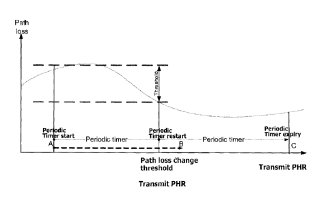
[20] FIG. 5 is an exemplary view of transmitting a power headroom report
(PHR)
according to the related art. As depicted in the FIG. 5, if a new PHR
transmitted time
due to the path loss changes and a new PHR transmitted time due to the
expiration of
the periodic timer is relatively close, path loss thereafter is not
significantly changed.
CA 02724595 2010-11-16
CA 02724595 2012-12-12
Accordingly, information contained in the new PHR due to the expiration of the
periodic
timer is not much different from information contained in the new PHR due to
the path loss
changes. This may cause a great amount of radio resources waste. Namely, in
the related art,
there is a drawback of using unnecessary radio resource(s) during a PHR
transmission
procedure.
Summary
[21] The present invention may provide an improved method for effectively
transmitting a
power headroom report from a terminal to a base station, thereby preventing
unnecessary
radio resource usages causing by the related art.
[22] In accordance with one aspect of the invention, there is provided a
method of power
headroom reporting (PHR) in a wireless communications system. The method
involves
determining whether power headroom reporting is triggered, and determining
whether
allocated uplink resources accommodate a medium access control (MAC) control
element
related to the power headroom reporting, wherein the allocated uplink
resources
accommodate the MAC control element as a result of logical channel
prioritization. The
method further involves transmitting the MAC control element related to the
power
headroom reporting, if at least one power headroom reporting is determined to
be triggered
and if the allocated uplink resources are determined to accommodate the MAC
control
element.
[22a] The MAC control element may be included in a MAC protocol data unit
(PDU).
[22b] The MAC control element may be a PHR MAC control element.
[22c] The power headroom reporting may be triggered by at least one of a path
loss changes, a
periodic timer for a PHR transmission, and a configuration or reconfiguration
of the PHR
functionality.
[22d] The power headroom reporting may be triggered if the path loss is
changed more than a
threshold value.
[22e] The power headroom reporting may be triggered if the periodic timer for
the PHR
transmission expires.
[22f] The power headroom reporting may not be triggered if the reconfiguration
of the PHR
functionality is used to disable the function.
CA 02724595 2012-12-12
5a
[22g] The MAC control element may be transmitted based on a value of a power
headroom, and
the value of the power headroom may be obtained from a physical layer.
[22h] The method may involve starting or restarting a periodic PHR timer.
[23] The foregoing and other features, aspects and advantages of the
present invention will
become more apparent from the following detailed description of the present
invention when
taken in conjunction with the accompanying drawings.
Brief Description of Drawings
[24] The accompanying drawings, which are included to provide a further
understanding of the
invention and are incorporated in and constitute a part of this specification,
illustrate
embodiments of the invention and together with the description serve to
explain the
principles of the invention.
[25] In the drawings:
[26] FIG. 1 shows a network structure of an E-UMTS, a mobile communication
system,
applicable to the related art and the present invention;
[27] FIG. 2 shows an exemplary structure of a control plane of a radio
interface protocol
between a UE and a UTRAN (UMTS Terrestrial Radio Access Network) based on 3GPP
radio access network standards according to the related art;
[28] FIG. 3 shows an exemplary structure of a user plane of the radio
interface protocol
between the UE and the UTRAN based on 3GPP radio access network standards
according
to the related art;
[29] Fig. 4 is an exemplary view showing the operations of the dynamic
radio resource
allocation.
[30] FIG. 5 is an exemplary view of transmitting a power headroom report
(PHR) according to
the related art; and
[31] FIG. 6 is an exemplary view of transmitting a power headroom report
(PHR) according to
the present invention.
Detailed Disclosure
[32] One aspect of this disclosure relates to the recognition by the
present inventors about the
problems of the related art as described above, and further explained
hereafter. Based upon
this recognition, the features of this disclosure have been developed.
CA 02724595 2012-12-12
=
6
[33] Although this disclosure is shown to be implemented in a mobile
communication system,
such as a UMTS developed under 3GPP specifications, this disclosure may also
be applied
to other communication systems operating in conformity with different
standards and
specifications.
[34] Hereinafter, description of structures and operations of the preferred
embodiments
according to the present invention will be given with reference to the
accompanying
drawings.
[35] In general, in order to prevent a waste of radio resource(s), a base
station may need to know
a power headroom reporting (PHR) of a terminal, thereby allocating a proper
radio
resource(s) for the terminal. A power headroom reporting procedure according
to the present
invention can be described as following. First, the power headroom reporting
procedure is
triggered by following conditions; 1) if a path loss changes more than a
threshold value after
a transmission of a PHR, 2) if a periodic PHR timer expires, or 3) if periodic
PHR procedure
or a PHR function is configured or reconfigured.
[36] If the power headroom reporting procedure is triggered by one of the
conditions, the
terminal may check whether there is any newly allocated uplink resource(s)
during a current
transmission time interval (TTI). If there is the allocated uplink
resource(s), the terminal may
receive a power headroom value from a physical layer. Thereafter, the terminal
may instruct
a multiplexing and assembly (MA) entity to generate a PHR MAC control element
(CE)
based on the power headroom value. During the above procedure, if the PHR is a
periodic
PHR, the periodic PHR timer is restarted.
[37] In general, the medium access control (MAC) layer is consisted of a
plurality of entities,
and each of the plurality of entities performs each own designated function.
Among the
plurality of entities, there is a multiplexing and assembly (MA) entity. The
MA entity
usually determines how to use an allocated radio resource for which data
transmission.
Further, the MA entity may generate or configure a MAC protocol data unit
(PDU) based on
such determination. For example, if the terminal receives a radio
7
WO 2009/154403 PCT/KR2009/003252
resource that allows to transmit 200 data bits, if a first logical channel has
150 trans-
mittable data bits and a second logical channel has another 150 transmittable
data bits,
the MA entity may configure how much amount of data from each logical channel
should be used, and then may generate the MAC PDU based on such configuration.
In
general, even if the radio resource(s) is allocated, all stored data in each
of logical
channels or all MAC CE (Control Element) generated in the MAC entity do not
always
be transmitted. Namely, when the PHR is triggered, even if the MAC entity
receives an
allocated radio resource(s), the PHR does not always be transmitted through
the
allocated radio resource(s). In other words, if the MA entity decides to
transmit other
high prioritized data rather than the PHR MAC CE, the MAC PDU does not include
the PHR. In this case, since the base station fails to receive the PHR from
the terminal,
the radio resource may also not be properly allocated.
[38] As aforementioned, this disclosure proposes to provide a method of
effectively
transmitting a power headroom report (PHR) from a terminal to a base station.
[39] FIG. 6 is an exemplary view of transmitting a power headroom report
(PHR)
according to the present invention.
[40] As depicted in the FIG. 6, according to the present invention, the
terminal may restart
a periodic PHR timer whenever the terminal transmits a PHR (or a periodic PHR)
to
the base station. Also, the terminal may restart the periodic PHR timer when a
PHR is
transmitted due to changes of a path loss. In the FIG. 6, according to the
related art, a
PHR has to be transmitted to the base station at a time B, as the periodic PHR
timer
expires at the time B. However, since the periodic PHR timer is restarted at a
time
when the PHR is transmitted due to the changes of the path loss, the PHR does
not be
transmitted to the base station at the time B, rather the PHR is transmitted
to the base
station at a time C when the restarted periodic timer expires. Accordingly,
the present
invention minimizes a number of unnecessary PHR transmissions.
[41] Therefore, a first embodiment of power headroom reporting procedure
according to
the present invention can be described as following. First, the power headroom
reporting procedure is triggered by following conditions; 1) if a path loss
changes more
than a threshold value after a transmission of a PHR, 2) if a periodic PHR
timer
expires, or 3) if periodic PHR procedure or a PHR function is configured or re-
configured.
[42] If the power headroom reporting procedure is triggered by one of the
conditions, the
terminal may check whether there is any newly allocated uplink resource(s)
during a
current transmission time interval (TTI). If there is the allocated uplink
resource(s), the
terminal may receive a power headroom value from a physical layer. Thereafter,
the
terminal may instruct a multiplexing and assembly (MA) entity to generate a
PHR
MAC control element (CE) based on the power headroom value. During the above
CA 02724595 2010-11-16
8
WO 2009/154403 PCT/KR2009/003252
procedure, if the PHR is a periodic PHR, the periodic PHR timer is restarted.
[43] Further, the present invention proposes to operate a power headroom
reporting
procedure based on a determination of multiplexing and assembly (MA) entity.
More
particularly, the MA entity determines whether a new MAC PDU can accommodate a
PHR MAC control element (or MAC PHR CE). If it is determined that the new MAC
PDU can not accommodate the PHR MAC CE, the PHR procedure is not triggered. In
this case, the PHR MAC CE is not included in the new MAC PDU. In contrast, if
the
new MAC PDU can accommodate the PHR MAC CE, the PHR procedure may be
triggered and the PHR may be transmitted after considering additional
conditions. In
this case, a periodic PHR timer is restarted, the PHR MAC CE is included in he
new
MAC PDU, and the new MAC PDU is transmitted.
[44] Further, if a new uplink resource(s) is allocated, the MA entity may
determine which
data of logical channel or which MAC CE should be transmitted through the
newly
allocated uplink resource(s). After determination, if the MAC PDU accommodates
the
MAC PHR CE, the MA entity may notify this to the PHR procedure. Based on this
no-
tification, the PHR procedure may determines whether to trigger the PHR
considering
with a changes of path loss or a periodic PHR timer. If the PHR is triggered,
the MA
entity is instructed to include the PHR into the MAC PDU. Namely, if a
triggered
MAC PHR CE and a newly allocated resource(s) are existed, and if the newly
allocated resource(s) can accommodate the MAC PHR CE, the MAC PHR CE is
included in a MAC PDU, and the MAC PDU is transmitted thereafter.
[45] Therefore, a second embodiment of power headroom reporting procedure
according
to the present invention can be described as following. First, the power
headroom
reporting procedure is triggered by following conditions; 1) if a path loss
changes more
than a threshold value after a transmission of a PHR, 2) if a periodic PHR
timer
expires, or 3) if periodic PHR procedure or a PHR function is configured or re-
configured.
[46] If the power headroom reporting procedure is triggered by one of the
conditions, the
terminal may check whether there is any new PHR transmission after recent
transmission of the PHR. After, if there is the new PHR transmission, the
terminal may
check whether there is any newly allocated uplink resource(s). If there is the
new
allocated uplink resource(s), the terminal may determine whether a MAC PDU,
which
will be transmitted through the new allocated uplink resource(s), can
accommodate a
PHR MAC CE as a result of a prioritization (i.e. logical channel
prioritization). Then,
if the new allocated resource can accommodate the PHR MAC CE, the terminal may
receive a power headroom value from a physical layer. Thereafter, the terminal
may
instruct a multiplexing and assembly (MA) entity to generate a PHR MAC control
element (CE) based on the power headroom value. Then, the terminal may restart
a
CA 02724595 2010-11-16
9
WO 2009/154403 PCT/KR2009/003252
periodic PHR timer, and may cancel all PHR after restarting the periodic PHR
timer.
[47] Further, the present invention proposes to consider a type of PHR
setting during a
power headroom reporting procedure. Specifically, if a setting for the PHR
procedure
changes, it is determined whether to trigger the PHR or not based on the type
of PHR
setting. More particularly, if the PHR setting is changed by an upper layer
(i.e., RRC
layer), the prevent invention proposes to determine whether the change of the
PHR
setting indicates a termination of the PHR procedure. Thereafter, if the
change of the
PHR setting indicates to terminate the PHR procedure, the PHR is not
triggered. In
contrast, if the change of the PHR setting does not indicate to terminate the
PHR
procedure, the PHR may be triggered.
[48] Therefore, a third embodiment of power headroom reporting procedure
according to
the present invention can be described as following. First, the power headroom
reporting procedure is triggered by following conditions; 1) if a path loss
changes more
than a threshold value after a transmission of a PHR, 2) if a periodic PHR
timer
expires, 3) upon configuration of a PHR function, or 4) upon reconfiguration
of PHR
function, where the PHR reconfiguration is not used to disable the PHR
function.
[49] If the power headroom reporting procedure is triggered by one of the
conditions, the
terminal may check whether there is any new PHR transmission after recent
transmission of the PHR. After, if there is the new PHR transmission, the
terminal may
check whether there is any newly allocated uplink resource(s). If there is the
new
allocated uplink resource(s), the terminal may determine whether a MAC PDU,
which
will be transmitted through the new allocated uplink resource(s), can
accommodate a
PHR MAC CE as a result of a prioritization (i.e. logical channel
prioritization). Then,
if the new allocated resource can accommodate the PHR MAC CE, the terminal may
receive a power headroom value from a physical layer. Thereafter, the terminal
may
instruct a multiplexing and assembly (MA) entity to generate a PHR MAC control
element (CE) based on the power headroom value. Then, the terminal may restart
a
periodic PHR timer, and may cancel all PHR after restarting the periodic PHR
timer.
[50] Here, The PHR MAC CE metioned in this disclosure is identified by a
MAC PDU
subheader with LCID, and it has a fixed size and consists of a single octet.
[51] Further, as explained above, the Power Headroom reporting
(PHR)procedure is used
to provide the serving eNB with information about the difference between the
nominal
UE maximum transmit power and the estimated power for uplink (i.e., UL-SCH)
transmission. RRC controls Power Headroom reporting by configuring the two
timers
periodicPHR-Timer and prohibitPHR-Timer, and by signalling path loss (i.e., dl-
PathlossChange) which sets the change in measured downlink pathloss to trigger
a
PHR.
[52] According to the presnet invention, a procedure text can be given as
following:
CA 02724595 2010-11-16
10
WO 2009/154403 PCT/KR2009/003252
[53] A Power Headroom Report (PHR) shall be triggered if any of the
following events
occur:
[54] - prohibitPHR-Timer expires or has expired and the path loss has
changed more than
dl-PathlossChange dB since the transmission of a PHR when UE has UL resources
for
new transmission;
[55] - periodicPHR-Timer expires;
[56] - upon configuration or reconfiguration of the power headroom
reporting func-
tionality by upper layers [8], which is not used to disable the function.
[57] If the UE has UL resources allocated for new transmission for this
TTI:
[58] - if the Power Headroom reporting procedure determines that at least
one PHR has
been triggered since the last transmission of a PHR or this is the first time
that a PHR
is triggered, and;
[59] - if the allocated UL resources can accommodate a PHR MAC control
element as a
result of logical channel prioritization:
[60] - obtain the value of the power headroom from the physical layer;
[61] - instruct the Multiplexing and Assembly procedure to generate and
transmit a PHR
MAC control element based on the value reported by the physical layer;
[62] - start or restart periodicPHR-Timer;
[63] - start or restart prohibitPHR-Timer;
[64] - cancel all triggered PHR(s).
[65] The present disclosure may provide a method of providing a power
headroom
reporting (PHR) in wireless communications system, the method comprising: de-
termining whether the power headroom reporting is triggered; determining
whether
allocated uplink resources accommodate a medium access control (MAC) control
element related to the power headroom reporting if at least one power headroom
reporitng is determined to be triggered; and transmitting the MAC control
element
based on a value of a power headroom if the allocated uplink resources are
determined
to accommodate the MAC control element, wherein the MAC control element is
included in a MAC protocol data unit (PDU), the MAC control element is a PHR
MAC
control element, the power headroom reporting is triggered by at least one of
a path
loss changes, a periodic timer for a PHR transmission, and a configuration or
recon-
figuration of the PHR functionality, the power headroom reporting is triggered
if the
path loss is changed more than a threshold value, the power headroom reporting
is
triggered if the periodic timer for the PHR trnamsision expires, the power
headroom
reproting is not triggered if the reconfiguration of the PHR functionality is
used to
disable the function, the allocated uplink resources accommodate the MAC
control
element as a result of logical channel prioritization, and the value of the
power
headroom is obtained from a physical layer.
CA 02724595 2010-11-16
CA 02724595 2012-12-12
=
11
[66] Although the present disclosure is described in the context of mobile
communications, the
present disclosure may also be used in any wireless communication systems
using mobile
devices, such as PDAs and laptop computers equipped with wireless
communication
capabilities (i.e. interface). Moreover, the use of certain terms to describe
the present
disclosure is not intended to limit the scope of the present disclosure to a
certain type of
wireless communication system. The present disclosure is also applicable to
other wireless
communication systems using different air interfaces and/or physical layers,
for example,
TDMA, CDMA, FDMA, WCDMA, OFDM, EV-DO, Wi-Max, Wi-Bro, etc.
[67] The exemplary embodiments may be implemented as a method, apparatus or
article of
manufacture using standard programming and/or engineering techniques to
produce
software, firmware, hardware, or any combination thereof. The term "article of
manufacture"
as used herein refers to code or logic implemented in hardware logic (e.g., an
integrated
circuit chip, Field Programmable Gate Array (FPGA), Application Specific
Integrated
Circuit (ASIC), etc.) or a computer readable medium (e.g., magnetic storage
medium (e.g.,
hard disk drives, floppy disks, tape, etc.), optical storage (CD-ROMs, optical
disks, etc.),
volatile and non-volatile memory devices (e.g., EEPROMs, ROMs, PROMs, RAMs,
DRAMs, SRAMs, firmware, programmable logic, etc.).
[68] Code in the computer readable medium may be accessed and executed by a
processor.
The code in which exemplary embodiments are implemented may further be
accessible
through a transmission media or from a file server over a network. In such
cases, the article
of manufacture in which the code is implemented may comprise a transmission
media, such
as a network transmission line, wireless transmission media, signals
propagating through
space, radio waves, infrared signals, etc. Of course, those skilled in the art
will recognize that
many modifications may be made to this configuration without departing from
the scope of
the present disclosure, and that the article of manufacture may comprise any
information
bearing medium known in the art.
[69] While specific embodiments of the invention have been described and
illustrated, such
embodiments should be considered illustrative of the invention only and not as
limiting the
invention as construed in accordance with the accompanying claims.