Note: Descriptions are shown in the official language in which they were submitted.
CA 02724874 2010-12-10
EXTENDABLE TRAILER WITH NON-BOX BEAM
This application claims priority on US Patent Application No.
12/697,448 filed February 1, 2010, incorporated herein by reference.
This invention pertains generally to trailers and more specifically to
extendable trailers.
It is well known to use semi-tractor and trailers to haul a variety of
different loads.
It is also known to have extendable trailers, which can be lengthened
or shortened depending upon the size of the load. The extendable trailers
have a telescoping beam, which allows the trailer to change length. The
cross-section of known telescoping beams is typically rectangular or circular.
While known beams work well for their intended use, each shape has its own
strengths and weakness depending upon how the beam is loaded.
Therefore, what is needed is an extendable trailer with a telescoping
beam having an optimized shaped cross-section for handling forces from
many different directions.
According to one embodiment of this invention, an extendable trailer
frame includes at least one ground engaging wheel for supporting the
extendable trailer frame; a connection device for operatively connecting the
extendable trailer frame to an associated tractor; a first support assembly; a
second support assembly; and a tubular beam assembly operatively
connecting the first and second support assemblies, the tubular beam
assembly having first and second telescopically joined members, wherein the
length of the tubular beam assembly changes as the first and second
telescopically joined members move in relation to each other, and wherein
one of the first and second telescopically joined members have a cross-
section comprising a plurality of curvilinear portions. The plurality of
curvilinear portions may join together at any angle. In one embodiment, the
plurality of curvilinear portions are joined together at obtuse angles. The
extendable trailer frame may include a locking mechanism having a locked
CA 02724874 2010-12-10
Page 2 of 18
condition and an unlocked condition, wherein the locked condition maintains
the length of the tubular beam assembly, and wherein the unlocked condition
allows the length of the tubular beam assembly to adjust. The extendable
trailer frame may include one or more adjustment mechanisms for changing
the length of the tubular beam assembly. In one embodiment, the
adjustment mechanism is a hydraulic cylinder. The extendable trailer frame
may include a second tubular beam assembly operatively connecting the first
and second support assemblies, the second tubular beam assembly having
first and second telescopically joined members, wherein the length of the
tubular beam assembly changes as the first and second telescopically joined
members move in relation to each other, and wherein a cross-section of the
telescopically joined members has a plurality of curvilinear portions joined
together at obtuse angles. In one embodiment, the cross-section of the
telescopically joined members includes a substantially linear portion
positioned between two curvilinear portions, wherein the substantially linear
portion and the two curvilinear portions are joined together at obtuse angles.
The tubular beam assembly may be positioned in a variety of ways.
Changing the length of the tubular beam assembly may change the length or
the width of the extendable trailer frame. In one embodiment, both the first
and second telescopically joined members have cross-sections comprising a
plurality of curvilinear portions joined together at obtuse angles.
According to another embodiment of this invention, an extendable
trailer includes at least one ground engaging wheel operatively connected to
the extendable trailer for supporting the extendable trailer; a connection
device operatively connected to the extendable trailer for connecting the
extendable trailer to an associated tractor; a load receiving surface; and an
extendable trailer frame. The extendable trailer frame may include a front
support assembly; a rear support assembly; and a tubular beam assembly
operatively connecting the front and rear support assemblies, the tubular
beam assembly having first and second telescopically joined members,
CA 02724874 2010-12-10
Page 3 of 18
wherein the length of the extendable trailer frame changes as the first and
second telescopically joined members move in relation to each other, and
wherein a cross-section of the telescoping joined members includes a
plurality of outwardly curved portions. The outwardly curved portion may
join together at any angle. In one embodiment, the outwardly curved
portions joined together at obtuse angles. The cross-section of the
telescopically joined members may include three outwardly curved portions
joined together at obtuse angles. The cross-section of the telescopically
joined members may include a substantially linear portion positioned
between two outwardly curved portions, wherein the substantially linear
portion and the two outwardly curved portions are joined together at obtuse
angles.
One advantage of this invention is the enhanced strength and rigidity
of the telescoping beam.
Another advantage of this invention is the increase in load bearing
without the increase in the amount, thickness, or weight of material used for
the telescoping beam.
Still other benefits and advantages of the invention will become
apparent to those skilled in the art to which it pertains upon a reading and
understanding of the following detailed specification.
The invention may take physical form in certain parts and
arrangement of parts, embodiments of which will be described in detail in
this specification and illustrated in the accompanying drawings which form a
part hereof and wherein:
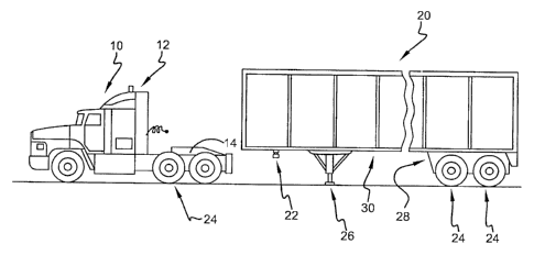
FIGURE 1 is a perspective view of a semi-tractor and an extendable
trailer, according to one embodiment;
FIGURE 2 is a perspective view of a semi-tractor and an extendable
trailer, according to another embodiment;
FIGURE 3 is a partial side view of the extendable trailer frame shown
in FIGURE 2;
CA 02724874 2010-12-10
Page 4 of 18
FIGURE 4 is a perspective view of an extendable trailer frame,
according to one embodiment;
FIGURE 5 is a top view of the extendable trailer frame shown in
FIGURE 4;
FIGURE 6 is a side view of the extendable trailer frame shown in
FIGURE 4;
FIGURE 7 is a top view of an extendable trailer frame, according to
another embodiment;
FIGURE 8 is cross-sectional view of the extendable trailer frame shown
in FIGURE 7;
FIGURE 9 is perspective view of an extension device, according to one
embodiment;
FIGURE 10 is cross-sectional view of the tubular beam assembly
shown in FIGURE 5, according to one embodiment;
FIGURE 11 is cross-sectional view of the tubular beam assembly
shown in FIGURE 5, according to another embodiment;
FIGURE 12 is cross-sectional view of the tubular beam assembly
shown in FIGURE 5, according to another embodiment;
FIGURE 13 is cross-sectional view of the tubular beam assembly
shown in FIGURE 5, according to another embodiment;
FIGURE 14 is cross-sectional view of the tubular beam assembly
shown in FIGURE 5, according to another embodiment;
FIGURE 15 is cross-sectional view of the tubular beam assembly
shown in FIGURE 5, according to another embodiment.
Referring to the drawings wherein the showings are for purposes of
illustrating embodiments of the invention only and not for purposes of
limiting the same, and wherein like reference numerals are understood to
refer to like components, FIGURES 1 and 2 show a tractor 10 and an
extendable trailer 20 for transporting various goods, according to an
embodiment of this invention. The tractor 10 may be any type of semi-
tractor, semi-truck, semi-trailer truck, or tractor-trailer. The tractor 10
may
CA 02724874 2010-12-10
Page 5 of 18
include a cab 12 and fifth wheel 14, as is well known in the art. The
extendable trailer 20 may be any type of trailer including, but not limited
to,
a flatbed trailer, a lowboy trailer, a dump trailer, a tagalong trailer, a box
or
van trailer, a curtain slider trailer, a drop-deck trailer, a gooseneck
trailer, or
a double-decker trailer. The trailer 20 may include a connection device 22
for connecting to the fifth wheel 14 of the tractor 10. In one embodiment,
the connection device 22 is a kingpin, as is well known in the art. The
trailer
20 may include a wheel or undercarriage assembly 28. The trailer 20 may
include one or more ground-engaging wheels 24 for supporting the rear of
the trailer 20. The trailer 20 may include a retractable landing gear
assembly 26 for supporting the front of the trailer 20, when the trailer 20 is
not connected to the tractor 10. The trailer 20 may include an extendable
frame 30, which may extend and retract to change any dimension of the
trailer 20 chosen with ordinary skill in the art. In one embodiment, the
frame 30 extends and retracts the trailer 20 along the length or longitudinal
axis L of the trailer 20, shown in FIGURES 2-6. In another embodiment, the
frame 30 extends and retracts the trailer 20 along the width or transverse
axis T of the trailer, shown in FIGURE 7. The extendable frame 30 may
receive and support different sized shipping containers 40, including, but not
limited to, standard sized shipping containers. The extendable frame 30 may
be formed of metal.
With reference now to FIGURES 2-6, the trailer frame 30 may include
a front support assembly 40, a rear support assembly 50, and a tubular
beam assembly 80. The front support assembly 40 may include a connection
device 22, a front cross member 42, one or more intermediate cross
members 44, a rear cross member 46, and side rails 48. The rear support
assembly 50 may include one or more undercarriage support members 32, a
rear cross member 52, one or more intermediate cross members 54, a front
cross member 56, and side rails 58. The cross members may maintain the
position and orientation of the side rails. The cross members may extend
between the side rails or across the top or bottom of the side rails or across
CA 02724874 2010-12-10
Page 6 of 18
the ends of the side rails. The cross members may extend between one or
both of the side rails and the tubular beam assembly 80. The cross members
may extend at least partially inside a portion of the tubular beam assembly
80. The cross members may maintain the position and orientation of the
tubular beam assembly 80 in relation to the side rails. The tubular beam
assembly 80 may extend from the front cross member 42 of the front
support assembly 40 to the rear cross member 52 of the rear support
assembly 50. Alternatively, the tubular beam assembly 80 may extend from
any portion of the front support assembly 40 to any portion of the rear
support assembly 50. In one embodiment, the tubular beam assembly 80
extends from the rear cross member 46 of the front support assembly 40 to
the rear cross member 52 of the rear support assembly 50. In another
embodiment, the tubular beam assembly 80 extends from the rear cross
member 46 of the front support assembly 40 to the front cross member 56 of
the rear support assembly 50.
With continuing reference to FIGURES 2-6, the tubular beam assembly
80 may include a front section 81 and a rear section 82, which are sized to
fit
together telescopically. The fit between the front section 81 and the rear
section 82 can be any type of fit chosen with ordinary skill in the art
including, but not limited to a clearance fit. In one embodiment, the front
section 81 may telescopically receive the rear section 82. In another
embodiment, the rear section 82 may telescopically receive the front section
81. The front section 81 may include one or apertures 86 at predetermined
distances along the tubular beam assembly 80. The rear section 82 may
include one or apertures 86 at predetermined distances along the tubular
beam assembly 80. The length of the tubular beam assembly 80 can be
adjusted by the relative movement between the front section 81 and the rear
section 82. Either section 81, 82 could be fixed in relation to the other
section or both section 81, 82 could be movable. The length of the tubular
beam assembly 80 can be set at a specific length when the apertures 86 on
the front section 81 and rear section 82 are aligned and then a locking
CA 02724874 2010-12-10
Page 7 of 18
mechanism 88 is inserted into the aligned apertures 86. The locking
mechanism 88 may be a bar or pin inserted into the apertures 86. In one
embodiment, changing the length of the tubular beam assembly 80 changes
the length of the trailer 20 along the longitudinal axis L of the trailer 20.
In
another embodiment, changing the length of the tubular beam assembly 80
changes the width of the trailer 20 along the transverse axis T of the trailer
20. The tubular beam assembly 80 may provide a conduit for electrical
cables and hydraulic conduits to pass through. Any of the frame members,
rails, or assemblies may have any shape chosen with ordinary skill in the art
including, but not limited to, a rectangular bar or tube, an elliptical bar or
tube, a circular bar or tube, an I-beam, an H-beam, an L-beam, an angle
iron, and a flat metal plate. Any of the frame members, rails, or assemblies
may be attached by any means chosen with ordinary skill in the art including,
but not limited to, welding and fasteners.
With reference now to FIGURES 7 and 8, the tubular assembly 80 may
include a left section 83 and a right section 84. The left and rights section
83, 84 may telescopically interconnect, where the left section 83 may
telescopically receive the right section 84 or the right section 84 may
telescopically receive the left section 83. The length of the tubular beam
assembly 80 can be adjusted by the relative movement between the left
section 83 and the right section 84. The tubular assembly 80 may also
include a center section 85. The center section 85 may telescopically receive
the left section 83 and/or the right section 84. The length of the tubular
beam assembly 80 can be adjusted by the relative movement between the
left section 83 and the center section 85, and/or between the right section 84
and the center section 85. In one embodiment, an adjustment mechanism
34 may extend and retract the left and right sections 83, 84, shown in
FIGURE 8. In another embodiment, the adjustment mechanism 34 may
extend and retract the front and rear sections 81, 82, shown in FIGURE 9. In
one embodiment, the adjustment mechanism 34 is a hydraulic cylinder. In
another embodiment, the adjustment mechanism 34 is a pneumatic cylinder.
CA 02724874 2010-12-10
Page 8 of 18
With reference now to FIGURES 10-15, the cross section 110 of the
tubular beam assembly 80 (including the telescoping front and rear sections
81, 82; the left and right sections 83, 84; and the center section 85) may
include a plurality of curvilinear portions or segments, which join together
at
obtuse angles. In one embodiment, the curvilinear portions or segments
have a substantially outwardly curved shape. In another embodiment, the
curvilinear portions or segments have a substantially arc shape including, but
not limited to, a circular arc, an elliptical arc, or a hyperbolic arc. The
cross
section 110 of the tubular beam assembly 80 may include substantially
straight or linear portions or segments. The curvilinear segments may join
together at any angle including, but not limited to a reflex angle, a straight
angle, an obtuse angle, a right angle, or an acute angle. The curvilinear and
substantially linear segments may join together at any angle including, but
not limited to a reflex angle, a straight angle, an obtuse angle, a right
angle,
or an acute angle. The substantially linear segments may join together at
any angle including, but not limited to a reflex angle, a straight angle, an
obtuse angle, a right angle, or an acute angle. The cross section 110 of the
tubular beam assembly 80 may include an upper profile 111 and a lower
profile 112 which are connected to each other, such as by welding, at weld
113. The upper profile 111 and the lower profile 112 may join together at
any angle including, but not limited to a reflex angle, a straight angle, an
obtuse angle, a right angle, or an acute angle. In one embodiment, the
upper profile 111 and the lower profile 112 have approximately the same
vertical height.
With reference now to FIGURES 10-12, the upper profile 111 may
include a substantially linear central segment 101, which extends
symmetrically to both sides of the vertical longitudinal plane 114 of the
section. In one embodiment, this central portion 101 forms the longest
substantially linear cross-sectional segment of the upper profile 111. In
another embodiment, the length of the central substantially linear portion
101 is equal to or shorter than the length of substantially linear cross-
CA 02724874 2010-12-10
Page 9of18
sectional portion 103. In another embodiment, the lengths of the
substantially linear cross-sectional portions 103 are equal to or shorter than
the lengths of the third substantially linear portions 105. The upper profile
111 may include outwardly curved cross-sectional segments 102 connected
to each side of the cross-sectional segment 101. The upper profile 111 may
include substantially linear cross-sectional segments 103 connected to the
outwardly curved cross-sectional segments 102. The upper profile 111 may
include outwardly curved cross-sectional segments 104 connected to the
substantially linear cross-sectional segments 103. The upper profile 111 may
include substantially linear cross-sectional segments 105 connected to the
curved cross-sectional segments 104. In one embodiment, the outwardly
curved cross-sectional segments 102 have a smaller radius of curvature than
the outwardly curved cross-sectional segments 104.
With continuing reference to FIGURES 10-12, The substantially linear
cross-sectional segments 105 may form the lowermost or termination points
of the upper cross sectional section 111. At the lower edge of the
substantially linear cross-sectional segments 105, the upper profile 111 may
be connected to the lower profile 112 at location 113. In one embodiment,
the upper profile 111 includes five substantially linear cross-sectional
segments 101, 103, 103, 105, 105 and four outwardly curved cross-sectional
segments 102, 102, 104, 104. In a more specific embodiment, the
substantially linear segments alternate with the outwardly curved segments.
In one embodiment, the transitions between the substantially linear
segments and the outwardly curved segments are tangential or at straight
angles. In another embodiment, the transitions between the substantially
linear segments and the outwardly curved segments are at obtuse angles.
The curved cross-sectional segments may act as stiffeners to counteract
buckling. The substantially linear cross-sectional segments may facilitate
manufacturing the tubular beam assembly 80.
CA 02724874 2010-12-10
Page 10 of 18
With reference to FIGURES 13-15, the cross section 110 of the tubular
beam assembly 80 may include two profile sections 111, 112. Both profile
section 111, 112 may include substantially straight or linear portions or
segments 212a and 214a. The lower profile 112 may be formed by three
outwardly curved shell segments 214b, 214c and 214d, as shown in FIGURE
13. Segments 214b and 214d may each include one of the substantially
straight or linear segments 214a, which are welded to the upper profile 111.
The upper profile 111 may include three outwardly curved shell segments
212b, 212c and 212d. Each segment 212b, 212c, 212d, 214b, 214c, and
214d may have the shape of a circular arc, with the same or different radii of
curvature. The two shell segments 212b and 212d may include the
substantially straight or linear segments 212a, which are welded to the
straight segments 214a of the lower profile 112. The shell segments 212b,
212c, and 212d may form obtuse angles with each other at their respective
meeting or connecting points and at the points where the shell segments
212b, 212d meet with the respective connecting straight segments 212a.
The lower profile segments 214a, 214b, 214c and 214d may form obtuse
angles with each other at their respective meeting or connecting points and
at the points where the shell segments 214b, 214d meet with the respective
connecting straight segments 214a.
With continuing reference to FIGURES 13-15, the upper profile 111
may include a substantially straight or linear shell segment 212e and a pair
of short outwardly curved segments 212f and 212g, which are connected to
the straight segment 212e, as shown in FIGURE 14. The curved segments
212f and 212g may also be connected to curved segments 212b, 212d,
respectively. Each of these segments may meet at obtuse angles as
discussed above. The upper and lower profiles 111, 112 may include other
substantially straight or linear segments or additional substantially straight
or
linear segments between the outwardly curved shell segments 212b and 212f
and between the outwardly curved shell segments 212g and 212d. The
upper and lower profiles 111, 112 may include at least two curved shell
CA 02724874 2010-12-10
Page 11 of 18
segments and may include any even or odd number of curved shell
segments.
With continuing reference to FIGURES 13-15, the upper profile 111
may includes a substantially linear or straight segment 212e, as shown in
FIGURE 15. Segment 212e may be joined at its ends to outwardly curved
shell segments 212g' and 212f' at the right and left upper corners of the
upper profile 111. Curved segments 212g' and 212f may have a relatively
small radius of curvature. Segments 212g' and 12f' may merge tangentially
or at straight angles into the central straight shell segment 212e on one side
and into the outwardly curved shell segments 212b' and 212d', respectively,
on their other sides. The outwardly curved segments of the tubular beam
assembly 80 may provide resistance to compressive forces. The relatively
sharp "creases" formed at the joints where the curved segments meet at
obtuse angles may provide enhanced stiffness.
With reference now to all the FIGURES, the operation of the
extendable trailer 20 will now be described. The extendable frame 30 may
extend and retract to change any dimension of the trailer 20 chosen with
ordinary skill in the art. The extendable frame 30 may extend and retract
the trailer 20 along the length or longitudinal axis of the trailer 20, or
along
the width or transverse axis of the trailer 20, or along both axes. By
changing a dimension of the trailer, the trailer 20 may receive and support
different sized loads. According to one embodiment, a dimension of the
extendable frame 30 can be changed by unlocking the locking mechanism
88, extending or retracting the frame 30, and then locking the frame 30 in
the new position. According to another embodiment, a dimension of the
extendable frame 30 can be changed by extending or retracting an
adjustment mechanism 34, which extends or retracts at least a portion of the
frame 30.
CA 02724874 2010-12-10
Page 12 of 18
Numerous embodiments have been described, hereinabove. It will be
apparent to those skilled in the art that the above methods and apparatuses
may incorporate changes and modifications without departing from the
general scope of this invention. It is intended to include all such
modifications and alterations in so far as they come within the scope of the
appended claims or the equivalents thereof.