Note: Descriptions are shown in the official language in which they were submitted.
CA 02724984 2010-11-19
1
DESCRIPTION
Title of the Invention
HOLLOW POROUS MEMBRANE AND PROCESS FOR PRODUCING THE SAME
Technical Field
[0001]
The present invention relates to a hollow porous membrane which is a
micro-filtration membrane or ultra-filtration membrane and which is suitable
for water
treatment and a process of producing the hollow porous membrane.
Priority is claimed on Japanese Patent Application No. 2008-133504, filed on
May 21, 2008, the content of which is incorporated herein by reference.
Background Art
[0002]
Recently, with an increase in interest in environmental contamination and
reinforcement of the regulation thereof, water treatment employing a membrane
method
using a filtration membrane excellent in completeness of separation or
compactness has
attracted attention. For use in water treatment, a filtration membrane
requires excellent
separation characteristic or water permeability and high mechanical strength.
[0003]
In the past, filtration membranes formed of polysulfone, polyacrylonitrile,
cellulose acetate, polyvinylidenefluoride, and the like using a wet or dry-wet
spinning
method were known as the filtration membrane excellent in water permeability.
Such
CA 02724984 2010-11-19
2
filtration membranes have a high-porosity and asymmetric structure through
microphase-separating a polymer solution and coagulating the polymer solution
in a
non-solvent.
[0004]
Among the materials of the filtration membranes, since the
polyvinylidenefluoride resin is excellent in chemical resistance and heat
resistance, it is
suitably used as the material of a separation membrane. However, the
filtration
membranes formed of a polyvinylidenefluoride hollow fiber membrane having been
proposed so far have a problem in that one of separation characteristic, water
permeability, and mechanical strength is not satisfactory and a process of
producing the
filtration membrane satisfying all the characteristics is complicated.
[0005]
A porous membrane in which a hollow braid is completely embeded in a
semi-permeable porous membrane to enhance the mechanical strength has been
proposed
(Patent Document 1). However, such a porous membrane has a problem in that the
water permeability thereof is low because it has a structure in which the
braid is
completely buried in the semi-permeable porous membrane and the porous
membrane
permeates most monofilaments.
[0006]
On the contrary, a separation membrane has been proposed in which a hollow
knitted braid is used as a support and a porous membrane is formed on the
surface
thereof to enhance both the mechanical strength and the water permeability
(Patent
Document 2). However, such a hollow porous membrane has a problem in that the
porous membrane can be easily peeled from the braid because the porous
membrane is
disposed on only the surface of the braid. Since large macro voids exist in a
membrane
CA 02724984 2010-11-19
3
structure, there is a problem in that the separation characteristic easily
deteriorates due to
damage of external causes on the outer surface of the membrane.
[0007]
The hollow braid used as the support is generally produced by a braiding
machine. The braiding machine produces a braid by drawing out yarns from
plural
bobbins disposed upright on a flat panel, intersecting and knitting the yarns,
and
changing the positional relations of the yarns in a predetermined pattern by
moving the
bobbins along a predetermined path. The braid produced by the braiding machine
and
the hollow porous membrane using the braid as a support has the following
problems.
[0008]
Problem 1
Since the bobbins segmenting the yarns into small groups move in a complex
way, the braiding speed of the braiding machine is low. Accordingly, there is
problem
in that the productivity of the support is low. When the productivity is low,
the cost of
the support increases, thereby causing an increase in cost of the hollow
porous membrane
using the support.
[0009]
Problem 2
The braiding speed of the braiding machine is lower by one or more digits than
the production speed of the hollow porous membrane. Accordingly, many braiding
machines are required for supplying supports necessary for continuously
producing the
hollow porous membrane. When the yarn on a bobbin in the braiding machine runs
out,
it is necessary to stop the braiding machine and to carry out a yarn piecing
operation such
as replacement of the bobbin, incorporation of a new yarn into the braid, and
cutting out
ends of yarns protruding from the surface of the braid by the number of times
of the
CA 02724984 2010-11-19
4
number of bobbins (the number of strokes of yarns)xthe number of braiding
machines.
Due to this complex operation, the cost of support increases, thereby causing
an increase
in the cost of the hollow porous membrane using the support.
[0010]
Problem 3
To obtain satisfactory adhesive property of the porous membrane layer to the
support, it is necessary to cause a part of the porous membrane layer to
satisfactorily
permeate the inside of the support. However, when the meshes of the braids are
dense
or the spaces between the monofilaments constituting the yarns are dense, a
membrane-forming dope cannot satisfactorily permeate the meshes or fibers of
the
support when forming the porous membrane layer and thus the porous membrane
layer is
easily peeled out of the support.
[0011]
On the other hand, a composite hollow fiber membrane without a defective
portion of 10 m or more has been proposed (Patent Document 3), which is
obtained by
applying a spinning dope including hydrophilic polymer as a non-solvent to a
reinforcing
material of a tubular knitted fabric in order to improve the separation
characteristic.
However, since the hollow fiber membrane has a dense layer, which affects the
separation characteristic, only in the vicinity of the outer surface thereof,
there is a
problem in that the separation characteristic due to damage of external causes
on the
outer surface easily deteriorates. Since the non-solvent is added to the
spinning dope,
the spinning dope easily gels and the stability of the production process
deteriorates.
Since the hollow fiber membrane employs the tubular knitted fabric as the
reinforcing
material to enhance the mechanical strength but the permeation distance of the
polymer
resin membrane into the reinforcing material is set to be less than 30% of the
thickness of
CA 02724984 2010-11-19
the reinforcing material to maintain the water permeability while enhancing
the
mechanical strength, there is a problem in that the strength and the water
permeability are
not satisfactorily consistent in view of the peeling resistance of the polymer
resin
membrane from the reinforcing material.
5 [0012]
On the contrary, a composite porous membrane has been proposed (Patent
Document 4 and 5), which is difficult to peel out of a support and which is
resistant to the
damage on the outer surface thereof and has excellent stability in separation
characteristic by providing two dense layers. However, since the porous
membrane
employs two membrane-forming processes to form two dense layers, the two
layers may
not be completely formed in a body. In this case, a gap may be generated
between the
layers and thus the outer layer may be easily peeled or damaged or defective
portions of
the layers may communicate with each other through the gap, thereby causing
the
deterioration in separation characteristics. There is a problem in that the
two layers may
not be completely formed in a body to maintain the water permeability and the
water
permeability and the peeling resistance are not consistent. A method of
causing a
membrane-forming solution with a low concentration of polymer to permeate
important
portions of a braid is employed to improve the peeling resistance between the
support
and the porous membrane layer. However, in this method, the adhesive portion,
serving
as a peeling-resistance agent, between the porous membrane layer and the
support is only
a fine porous portion permeating the fiber of the braid, this porous portion
is formed of
polymer with a low concentration to maintain the water permeability, and the
peeling
resistance can be improved, but there is still a problem with the strength.
Since
processes of producing and applying a diluted membrane-forming dope are
required and
two times of membrane-forming processes are employed, the production time is
long and
CA 02724984 2010-11-19
6
there is also a problem with production costs.
Patent Documents
[0013]
[Patent Document 1 ] Japanese Unexamined Patent Application, First
Publication Sho.53-132478
[Patent Document 2] United States Patent No. 5,472,607
[Patent Document 3] Japanese Laid-Open Patent Application No.
2003-225542
[Patent Document 4] Japanese Laid-Open Patent Application No. 2006-68710
[Patent Document 5] International Publication WO2004/043579
Summary of Invention
Problems to be Solved by the Invention
[0014]
An advantage of some aspects of the invention is that it provides a hollow
porous membrane with a reduced cost and excellent separation characteristic,
water
permeability, and mechanical strength and a process of producing the hollow
porous
membrane with an excellent adhesive property between a support and a porous
membrane layer at a low cost.
Means for Solving the Problem
[0015]
According to an aspect of the invention, there is provided a hollow porous
membrane including a porous membrane layer in which dense layers are disposed
in the
vicinities of an outer surface and an inner surface.
CA 02724984 2010-11-19
7
According to another aspect of the invention, there is provided a process of
producing the hollow porous membrane, in which membrane-forming dopes of a
first
membrane-forming dope and a second membrane-forming dope are successively
applied
and stacked onto the outer circumferential surface of a hollow support through
the use of
an annular nozzle and the applied membrane-forming dopes are simultaneously
coagulated.
According to another aspect of the invention, there is provided a hollow
porous
membrane including a hollow support and a porous membrane layer disposed on
the
outer circumferential surface of the support, wherein the support is a hollow
braid
obtained by circularly knitting a yarn formed of multi-filaments.
According to another aspect of the invention, there is provided a process of
producing a hollow porous membrane, wherein a porous membrane layer is formed
by
applying a membrane-forming dope containing a material of the porous membrane
layer
and a solvent to the outer circumferential surface of a hollow support and
coagulating the
applied dope, and a hollow braid obtained by circularly knitting a yarn formed
of
multi-filaments is used as the support.
Effects of the Invention
[0016]
The hollow porous membrane according to the above-mentioned aspects is
reduced in cost and excellent in separation characteristic, water
permeability, and
mechanical strength.
In the process of producing a hollow porous membrane according to the
above-mentioned aspects, it is possible to produce a hollow porous membrane
having an
excellent adhesive property between a support and a porous membrane layer at a
low
CA 02724984 2010-11-19
8
cost.
Brief Description of the Drawings
[0017]
FIG. 1 is a sectional view schematically illustrating a hollow porous membrane
according to the invention.
FIG. 2 is a side view illustrating a support formed of a hollow braid.
FIG. 3 is a side view illustrating an example of a known hollow braid.
FIG 4 is a diagram illustrating the structure of a hollow braid.
FIG. 5 is an enlarged view illustrating meshes of the hollow braid.
FIG. 6 is a diagram schematically illustrating the configuration of a support
producing apparatus.
FIG. 7 is a diagram schematically illustrating the configuration of a support
producing apparatus.
FIG. 8 is a diagram schematically illustrating the configuration of a hollow
porous membrane producing apparatus.
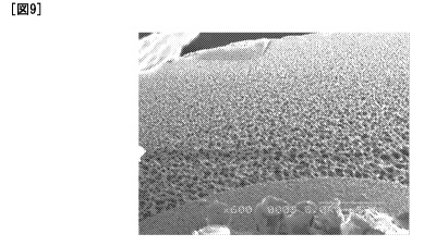
FIG. 9 is a schematic sectional view illustrating an example of a hollow
porous
membrane according to the invention.
FIG. 10 is a schematic sectional view illustrating an example of a hollow
porous
membrane according to the invention.
FIG. 11 is a schematic sectional view illustrating an example of a hollow
porous
membrane according to the invention.
FIG. 12 is a schematic sectional view illustrating an example of a hollow
porous
membrane according to the invention.
FIG. 13 is a schematic sectional view illustrating an example of a hollow
porous
CA 02724984 2010-11-19
9
membrane according to the invention.
FIG. 14 is a schematic sectional view illustrating an example of a hollow
porous
membrane according to the invention.
FIG. 15 is a schematic sectional view illustrating an example of a hollow
porous
membrane according to the invention.
FIG. 16 is a schematic sectional view illustrating an example of a hollow
porous
membrane according to the invention.
FIG. 17 is a schematic sectional view illustrating an example of a hollow
porous
membrane according to the invention.
FIG. 18 is a schematic sectional view illustrating an example of a hollow
porous
membrane according to the invention.
FIG. 19 is a schematic sectional view illustrating an example of a hollow
porous
membrane according to the invention.
FIG. 20 is a schematic sectional view illustrating an example of a hollow
porous
membrane according to the invention.
FIG. 21 is a schematic sectional view illustrating an example of a hollow
porous
membrane according to the invention.
Embodiments of the Invention
[0018]
Hereinafter, exemplary embodiments of the invention will be described.
[0019]
The thickness of a porous membrane layer constituting a hollow porous
membrane according to the invention is preferably set to be equal to or less
than 200 m.
By setting the thickness to be equal to or less than 200 m, permeation
resistance is
CA 02724984 2010-11-19
reduced during membrane separation to obtain excellent water permeability, the
coagulation time at the time of forming the porous membrane layer using a
membrane-forming dope which is a polymer resin solution can be reduced, macro
voids
(defective portions) can be effectively suppressed, and the productivity is
excellent.
5 The thickness is more preferably set to be equal to or less than 150 m.
The thickness of the porous membrane layer constituting the hollow porous
membrane according to the invention is preferably set to be equal to or more
than 100
m. By setting the thickness to be equal to or more than 100 m, it is possible
to obtain
mechanical strength causing no practical problem. However, a case where the
outer
10 diameter of the membrane is small is exceptional, because the mechanical
strength can be
maintained even with a thickness of less than 100 m.
[0020]
The porous membrane layer includes dense layers in the vicinities of the outer
surface and the inner surface, respectively. That is, in the hollow porous
membrane
according to the invention, even when the dense layer in the vicinity of the
outer surface
is damaged, it is possible to prevent the deterioration in separation
characteristic thanks
to the dense layer in the vicinity of the inner surface, thereby providing
stable separation
performance and high durability.
[0021]
Here, the dense layer means a region in which fine pores with smaller pore
diameters are collected in the porous membrane layer. In the invention, it is
preferable
that the average pore diameter of the dense layer is in the range of 0.01 to 2
m, to cause
both the water permeability and the separation performance of the hollow
porous
membrane to be consistent.
CA 02724984 2010-11-19
11
To make much of the separation performance, it is more preferable that the
average pore diameter of the dense layer in the vicinity of the outer surface
is in the range
of 0.01 to 1 m.
To make much of the water permeability and to avoid the increase in water
permeation resistance in the membrane, the average pore diameter of the dense
layer in
the vicinity of the inner surface is preferably in the range of 0.05 to 2 m
which is greater
than the average pore diameter of the dense layer in the vicinity of the outer
surface, and
more preferably in the range of 0.1 to 1.5 m.
[0022]
In the invention, the thickness of the dense layer is preferably in the range
of 10
to 125 m, to improve both the stability of the separation characteristic and
the water
permeability.
To improve the stability of the separation characteristic, the thickness of
the
dense layer in the vicinity of the outer surface is preferably in the range of
25 to 100 [im,
and more preferably in the range of 40 to 75 m.
To avoid the increase in water permeation resistance in the membrane, the
thickness of the dense layer in the vicinity of the inner surface is
preferable in the range
of 15 to 75 m which is smaller than that of the dense layer in the vicinity
of the outer
surface, and more preferably in the range of 20 to 50 m.
[0023]
To avoid the increase in water permeation resistance in the membrane, the
dense
layer in the vicinity of the outer surface is located preferably at a position
within 20 m
from the outer surface of the porous membrane layer. It is particularly
preferable that
the dense layer itself constitutes the outer surface of the porous membrane
layer.
CA 02724984 2010-11-19
12
[0024]
To avoid the dense layer in the vicinity of the outer surface and the dense
layer
in the vicinity of the inner surface from being simultaneously damaged due to
external
causes, the dense layer in the vicinity of the inner surface is preferably
located further
from the outer surface of the porous membrane layer and more preferably
located at a
position within 50 m from the inner surface of the porous membrane layer. It
is
particularly preferable that the dense layer itself constitutes the inner
surface of the
porous membrane layer.
When the hollow porous membrane according to the invention includes a porous
membrane layer on a support, the dense layer in the vicinity of the inner
surface is
preferably located at a position within 50 m from the outer surface of the
support and
more preferably located as a body with the support, to avoid the damage due to
external
causes. In this case, the dense layer means a portion exposed from the
support.
[0025]
The porous membrane layer preferably includes an intermediate porous layer
with an average pore diameter equal to or more than 2 m between the dense
layer in the
vicinity of the outer surface and the dense layer in the vicinity of the inner
surface.
Since the intermediate porous layer contributes to the water permeability in
the hollow
porous membrane according to the invention, the pore diameter thereof is
preferably
great. However, when the pore diameter thereof is excessively great, the pores
become
a macro void, which reduces the mechanical strength. Therefore, the average
pore
diameter of the intermediate porous layer is preferably equal to or less than
8 m and it is
more preferable that fine pores with a diameter equal to or greater than 10 m
are
substantially not present. The average pore diameter is more preferably in the
range of
CA 02724984 2010-11-19
13
3 to 5 m.
To improve the water permeability, it is preferable that the intermediate
porous
layer has an inclined structure in which the pore diameter gradually increases
from the
dense layer in the vicinity of the outer surface to the dense layer in the
vicinity of the
inner surface and the maximum pore-diameter portion exists between the two
dense
layers.
To cause both excellent water permeability and mechanical strength to be
consistent, it is preferable that the thickness of the intermediate porous
layer is in the
range of 50 to 150 pm.
[0026]
The hollow porous membrane according to the invention may include only the
above-mentioned porous membrane layer, but preferably includes the porous
membrane
layer on a hollow support to obtain excellent mechanical strength. Here, "on a
support"
is described to clarify the positional relation of the porous membrane layer
and the
support, but the porous membrane layer may permeate the inside of the support
through
meshes of the support.
[0027]
The support is not particularly limited, but any material may be properly
selected and used as long as it can be formed in a body with the porous
membrane layer.
A braid can be preferably used as the support, in that the production cost is
low, both the
flexibility and the shape stability (circularity) of a section can be
consistent, and the
adhesive property to the porous membrane layer is excellent. A hollow braid
obtained
by circularly knitting a yarn formed of multi-filaments can be particularly
preferably
used.
[0028]
CA 02724984 2010-11-19
14
In this case, the porous membrane layer and the support (hollow braid) need
not
be closely adhered to each other. However, when the adhesive property is low,
they
may be separated and the porous membrane layer may be peeled off at the time
of pulling
the hollow fiber membrane.
Therefore, it is preferable in the hollow porous membrane according to the
invention that a part of the porous membrane layer is made to permeate the
braid through
meshes of the hollow braid to form the porous membrane layer and the hollow
braid in a
body.
To give a satisfactory adhesive property to the porous membrane layer and the
support, it is preferable that the porous membrane layer permeates the hollow
braid by
50% or more of the thickness of the hollow braid. From the viewpoint of
peeling
resistance, it is more preferable that portions of the porous membrane layer
permeating
the braid through different meshes by 50% or more are connected to surround a
part of
the support. It is also preferable that the portions surrounding a part of the
support
extend in a fiber axis direction, because the peeling resistance further
increases. It is
more preferable that the connection in the fiber axis direction has a spiral
shape, because
the peeling resistance is markedly improved.
In this case, the thickness in the invention means the thickness of the
portion
exposed from the support.
[0029]
A process of producing a hollow porous membrane according to the invention
will be described below.
The hollow porous membrane according to the invention can be produced by
applying and stacking membrane-forming dopes of a first membrane-forming dope
and a
second membrane-forming dope, which contains a material of a porous membrane
layer
CA 02724984 2010-11-19
and a solvent, onto the outer circumferential surface of a hollow support
through the use
of an annular nozzle and simultaneously coagulating the membrane-forming
dopes.
In this case, the coagulation can go ahead from only one surface and a one-
body
porous membrane structure can be obtained from two species of membrane-forming
5 dopes by this method.
[0030]
For example, a double-annular nozzle shown in FIG. 1 of Patent Document 4 is
used, a hollow support (braid) is caused to pass through a passage of the
support, a first
membrane-forming dope (inner-layer membrane-forming dope) from a first supply
port
10 and a second membrane-forming dope (outer-layer membrane-forming dope) from
a
second supply port are simultaneously ejected, the first membrane-forming dope
is
applied onto the outer circumferential surface of the hollow braid, and then
the second
membrane-forming dope is applied onto the applied layer of the first membrane-
forming
dope. Thereafter, after idling for a predetermined time, by immersing and
coagulating
15 the resultant in a coagulation liquid and washing and drying the resultant,
it is possible to
obtain the structure of the hollow porous membrane according to the invention.
[0031]
When the double-annular nozzle is used, the first membrane-forming dope and
the second membrane-forming dope are merged in advance in the nozzle, and the
dopes
are simultaneously ejected from the nozzle surface and applied to the hollow
support.
By using a triple-annular nozzle having a central portion, an inner portion,
and
an outer portion, the membrane-forming dopes may be applied to the hollow
support by
simultaneously ejecting the first membrane-forming dope from the inner portion
and the
second membrane-forming dope from the outer portion while passing the hollow
support
through the central portion.
CA 02724984 2010-11-19
16
By using the above-mentioned annular nozzles, it is possible to uniformly
apply
the first membrane-forming dope and the second membrane-forming dope and not
to
generate bubbles between layers when the first membrane-forming dope and the
second
membrane-forming dope are stacked.
[0032]
Two types of membrane-forming dopes are used in the above-mentioned case,
but both the dopes contain a polymer resin, an additive, and an organic
solvent.
Examples of the polymer resin used in the membrane-forming dopes include a
polysulfone resin, a polyethersulfone resin, a sulfonated polysulfone resin,
polyvinylidenefluoride resin, a polyacrylonitrile resin, a polyimide resin,
polyamideimide
resins, or a polyesteramide resin. These can be properly selected and used as
needed,
and the polyvinylidenefluoride resin can be preferably used because it is
excellent in
chemical resistance.
[0033]
The additive can be used to control the phase-separation or the like, and
examples thereof include hydrophilic polymer resins such as mono-ols
represented by
polyethyleneglycol, diols, triols, and polyvinyl pyrrolidone. These can be
properly
selected and used as needed, and polyvinyl pyrrolidone can be preferable used
because it
is excellent in thickening effect.
[0034]
The organic solvent is not particularly limited as long as it can solve the
polymer
resins and the additives, and examples thereof include dimethylsulfoxide,
dimethylacetamide, and dimethylformamide.
[0035]
The compositions of the above-mentioned two types of membrane-forming
CA 02724984 2010-11-19
17
dopes are not particularly limited, and it is preferable that the solvent and
the polymer
resin used to form a one-body structure out of the two types of membrane-
forming dopes
at the time of coagulating the dopes are the same kinds, in that the peeling
of the layers is
prevented and the mechanical strength is improved.
[0036]
When the hollow porous membrane according to the invention is produced using
the above-mentioned method, the viscosity of the first membrane-forming dope
which is
a membrane-forming dope on the inner layer side is preferably higher than that
of the
second membrane-forming dope which is a membrane-forming dope on the outer
layer
side.
This is because the membrane-forming dopes are suppressed from excessively
permeating the inside of the hollow support by applying the first membrane-
forming
dope with higher viscosity onto the outer circumferential surface of the
hollow support,
thereby preventing the hollow portion of the hollow porous membrane from being
clogged.
To accomplish this effect, the first membrane-forming dope needs to have
satisfactory viscosity and the viscosity at 40 C is preferably equal to or
more than 50,000
Pa-sec. The viscosity is more preferably equal to or more than 100,000 Pa-sec
and still
more preferably equal to or more than 150,000 Pa-sec.
[0037]
The method of adjusting the viscosity of the membrane-forming dope is not
particularly limited, and may be carried out by changing the molecular weight
of the
polymer resin or changing the concentration of the polymer resin. A method of
blending two or more species of polymer resins with different molecular
weights may be
used to adjust the molecular weight of the polymer resin.
CA 02724984 2010-11-19
18
[0038]
The method of adjusting the viscosity of the membrane-forming dope can be
properly selected as described above, but it is preferable that the
concentration of the
polymer resin is adjusted in the first membrane-forming dope because the
generation of
macro voids can be suppressed in the inner layer where the coagulation speed
is low. It
is preferable that the concentration of the first membrane-forming dope is
raised because
it is possible to improve the structural stability of the entire porous layer.
On the other hand, it is preferable that the molecular weight of the polymer
resin
is adjusted in the second membrane-forming dope because the pore ratio in the
outer
surface of the porous membrane layer can be maintained to be high.
[0039]
When the membrane-forming dopes are coagulated to form a membrane as
described above, the porous structure is formed by phase-separation. Various
structures
can be obtained depending on the membrane-forming conditions. Representative
examples of the porous structure include three structures of a sponge
structure derived
from a sea-island structure in which the polymer resin is the sea, a particle-
aggregation
structure derived from a sea-island structure in which the polymer resin is
the islands,
and a three-dimensional mesh structure derived from a co-continuous structure
in which
the polymer resin and the solvent are wreathen in a network shape.
These structures can be properly selected. Since the particle-aggregation
structure can easily become a structure in which the polymer resin layer is
aggregated
and which reduces the mechanical strength, it is preferable in the invention
that the
sponge structure or the three-dimensional mesh structure is employed.
Since the sponge structure tends to become a homogeneous structure in which
the pore diameter does not greatly vary in the thickness direction, the sponge
structure is
CA 02724984 2010-11-19
19
a structure suitable for improving the stability of the separation
characteristic.
Since the three-dimensional mesh structure tends to become a structure in
which
the degree of communication between the pores is higher than that of the
sponge
structure, the three-dimensional mesh structure is suitable for improving the
permeability.
[0040]
The composition of the first membrane-forming dope which is the
membrane-forming dope on the inner layer side can be properly selected
depending on
the membrane structure to be formed.
In the condition for obtaining the sponge structure from the first
membrane-forming dope, the composition thereof is not particularly limited
similarly.
It is preferable that the mass ratio (additive/polymer resin) of the additive
and the
polymer resin in the membrane-forming dope is less than 0.45.
By setting the mass ratio to be less than 0.45, the homogeneous structure
tends
to become denser and macro voids are difficult to form.
When the mass ratio is excessively low, the pore diameter is excessively small
and thus the permeability tends to be lowered. Accordingly, the mass ratio is
preferably
set to be equal to or more than 0.3.
An example of the composition of the membrane-forming dope includes 20 to
30 mass% of polyvinylidenefluoride, 5 to 12 mass% of polyvinylpyrrolidone, and
60 to
85 mass% of dimethylacetamide. In this case, the mass ratio
(polyvinylpyrrolidone/polyvinylidenefluoride resin) of polyvinylpyrrolidone
and
polyvinylidenefluoride resins is preferably in the range of 0.3 to 0.45.
[0041]
The conditions for obtaining the three-dimensional mesh structure from the
first
membrane-forming dope is not particularly limited, but it is preferable that
the mass ratio
CA 02724984 2010-11-19
(additive/polymer resin) of the additive and the polymer resin in the membrane-
forming
dope is equal to or more than 0.45.
It is preferable that the ratio of the organic solvent is set to be equal to
or less
than 70 mass%. Accordingly, it is possible to suppress the generation of macro
voids
5 and to improve the entire structural stability of the porous membrane layer.
The ratio is
more preferably equal to or less than 68 mass%.
An example of the composition of the membrane-forming dope includes 20 to
mass% of polyvinylidenefluoride, 10 to 20 mass% of polyvinylpyrrolidone, and
55 to
68 mass% of dimethylacetamide. In this case, the mass ratio
10 (polyvinylpyrrolidone/polyvinylidenefluoride resin) of polyvinylpyrrolidone
and
polyvinylidenefluoride resins is preferably equal to or more than 0.45.
[0042]
The composition of the second membrane-forming dope which is the
membrane-forming dope on the outer layer side is not particularly limited as
long as it
15 can form a slope structure in which a dense layer is disposed in the
vicinity of the outer
surface of the porous membrane layer and the pore diameter gradually increases
toward
the inner surface of the porous membrane layer by phase-separation.
The composition of the second membrane-forming dope can be properly
selected depending on the membrane structure to be formed, but it is
preferable that the
20 ratio of the organic solvent is equal to or more than 70 mass% because the
surface pore
ratio of the porous membrane layer can be raised.
Since the slope structure having no large macro void can be formed, it is
preferable that the mass ratio of the additive and the polymer resin is equal
to or more
than 0.45. An example of the composition of the membrane-forming dope includes
15
25 to 25 mass% of polyvinylidenefluoride, 5 to 15 mass% of
polyvinylpyrrolidone, and 70
CA 02724984 2010-11-19
21
to 80 mass% of dimethylacetamide. In this case, the mass ratio
(polyvinylpyrrolidone/polyvinylidenefluoride resin) of polyvinylpyrrolidone
and
polyvinylidenefluoride resins is preferably equal to or more than 0.45.
[0043]
The thicknesses of the outer layer and the inner layer at the time of
application
can be properly set. However, when the thickness of the outer layer having the
higher
ratio of the organic solvent is great, the macro voids are easily generated at
the time of
forming the membrane. Accordingly, the thickness of the outer layer is
preferably equal
to or less than 150 m, more preferably equal to or less than 100 m, and
still more
preferably equal to or less than 80 m.
[0044]
When the hollow braid is used as the support, a non-solvent against the
membrane-forming dope may be buried in advance in the support to prevent the
excessive permeation of the membrane-forming dope into the support. An example
of
the non-solvent when the membrane-forming dope having the above-mentioned
composition is used is glycerin. Here, the non-solvent with excessively high
coagulation ability of the membrane-forming dope to be used or the non-solvent
with
excessively high viscosity is not suitable, because it hinders the porous
membrane layer
from permeating the inside of the support to greatly reduce the peeling
resistance.
[0045]
When polyvinylpyrrolidone is used as the additive, it is preferable that the
hollow porous membrane is chemical-washed using sodium hypochlorite in
cleaning
after the formation of the membrane structure from the coagulation.
[0046]
Hollow Porous Membrane
CA 02724984 2010-11-19
22
FIG. I is a sectional view schematically illustrating an example of the hollow
porous membrane according to the invention. The hollow porous membrane 1
includes
a hollow support 10 and a porous membrane layer 11 disposed on the outer
circumferential surface of the support 10.
[0047]
Support
FIG. 2 is a side view illustrating an example of the support. The support 10
is
formed of a hollow braid 12 obtained by circularly knitting a yarn 16. The
hollow braid
12 is different from the conventional hollow braid 14 shown in FIG. 3.
[0048]
The circular knitting means to organize a knit fabric using a circular
knitting
machine.
As shown in FIGS. 4 and 5, in the hollow braid 12, loops 17 (black part in FIG
5) are continuously formed in a spiral shape by bending the yarn 16 and the
loops 17 are
vertically connected. As shown in FIG. 5, meshes 18 are formed in the loops 17
and
between the loops 17.
[0049]
A multi-filament formed of plural mono-filaments is used as the yarn.
Examples of the fiber constituting the yarn include synthetic fiber,
semi-synthetic fiber, recycled fiber, and natural fiber.
[0050]
Examples of the synthetic fiber include polyamide fiber such as nylon 6, nylon
66, and aromatic polyamide, polyester fiber such as polyethyleneterephthalate,
polybutyreneterephthalate, polylactate, and polyglycolic acid, acryl fiber
such as
polyacrylonitrile, polyolefin fiber such as polyethylene and polypropylene,
CA 02724984 2010-11-19
23
polyvinylalcohol fiber, polyvinylidenechloride fiber, polyvinylchloride fiber,
polyurethane fiber, phenol resin fiber, fluorine fiber such as
polyvinylidenefluroide and
polytetrafluoroethylene, and polyalkylene paraoxybenzoate fiber.
[0051]
Examples of the semi-synthetic fiber include cellulose-derivative fiber using
as
raw materials cellulose diacetate, cellulose triacetate, chitin, and chitosan
and protein
fiber called promix.
Examples of the recycled fiber include cellulose recycled fiber (such as
rayon,
cuprammonium, and polynosic) obtained using a viscose method, a copper-ammonia
method, an organic solvent method, and the like.
Examples of the natural fiber include flax and jute.
[0052]
From the viewpoint of excellent chemical resistance, polyester fiber, acryl
fiber,
polyvinylalcohol fiber, polyamide fiber, polyolefin fiber, or
polyvinylchloride fiber can
be preferably used as the fiber, and polyester fiber, acryl fiber, or
polyvinylchloride fiber
can be particularly preferably used.
From the viewpoint of adhesion between the porous membrane layer 11 and the
support 10, fiber soluble in the solvent contained in the membrane-forming
dope can be
preferably used as the fiber. Examples of the fiber include acryl fiber and
polyvinylchloride.
[0053]
The multi-filament may be obtained by mixing two or more different species of
fiber.
The different species mean that at least one of fineness, mono-filament
length,
mechanical characteristic, and material is different.
CA 02724984 2010-11-19
24
For example, by combining plural species of fiber with different fineness to
provide fineness which could not be obtained from a single yarn, it is
possible to enhance
the degree of freedom in structure and characteristic of the support 10.
By combining expensive high-strength fiber with cheap general-use fiber with
small strength, the fineness for providing the outer diameter and the inner
diameter
necessary for the support 10 can be guaranteed by the general-use fiber and
the strength
insufficient only with the general-use fiber can be guaranteed by the high-
strength fiber,
thereby providing the support 10 with an excellent balance between cost and
strength.
When plural species of fiber with different materials are combined, for
example,
polyester fiber which is high in strength, low in cost, and excellent in
resistance to
hypochlorite used to wash the hollow porous membrane and acryl fiber which is
soluble
in the solvent contained in the membrane-forming dope, low in cost, and
excellent in
resistance to hypochlorite used to wash the hollow porous membrane.
[0054]
The fineness of the mono-filament is preferably equal to or less than 5 dtex,
and
more preferably equal to or less than 3 dtex. When the fineness of the mono-
filament is
equal to or less than 5 dtex and mono-filament ends of a yarn piecing portion
or a
fiber-ruptured portion protrude from the surface of the support 10, the
protruding
mono-filament ends can be selectively burned and removed by processing the
surface of
the support 10 with flame or can be thermally-contracted in the direction of
the surface of
the support 10, due to the small thermal conductivity or thermal capacity of
the
mono-filament, thereby preventing the mono-fiber ends from passing through the
porous
membrane layer 11. When the fineness of the mono-filament is equal to or less
than 3
dtex, the strength of the mono-filament is greatly reduced. Accordingly, even
when the
mono-filament ends of a yarn piecing portion or a fiber-ruptured portion
protrude from
CA 02724984 2010-11-19
the surface of the support 10, the mono-filament ends do not pass through the
porous
membrane layer 11 at the time of applying the membrane-forming dope.
When the mono-filament ends of a yarn-piecing portion or a fiber-ruptured
portion protruding from the surface of the support 10 at the time of applying
the
5 membrane-forming dope pass through the porous membrane layer 11, large
pinholes are
formed around the mono-filament ends or portions generated by peeling the
mono-filament and the porous membrane layer 11, which have been closely
adhered to
each other, by repeated stress actions become pinholes, thereby decreasing the
separation
characteristic of the hollow porous membrane 1.
10 [0055]
The number of loops 17 is preferably equal to or more than 5 per
circumference.
The number of loops 17 is equal to the number of knitting needles of the
circular knitting
machine to the described later. When the number of loops 17 is equal to or
more than 5,
the sectional shape of the hollow portion of the support 10 is substantially
circular, the
15 crush resistance to an external pressure is improved, and the decrease in
water
permeability due to a decrease in inner diameter is suppressed.
The upper limit of the number of loops 17 is determined depending on the outer
diameter of the hollow braid 12, the fineness of the yarn 16, the size of the
meshes, and
the like.
20 [0056]
The ratio (length/outer diameter) of the length of the loop 17 (black portion
in
FIG. 5) to the outer diameter of the support 10 is preferably in the range of
0.1 to 0.5.
When the ratio is equal to or more than 0.1, the loop 17 is deformed by a
bending or twist
force acting on the support 10, thereby providing the bending or twist
characteristic
25 necessary as the support. When the ratio is equal to or less than 0.5, the
crush resistance
CA 02724984 2010-11-19
26
of the support 10 can be maintained and the buckling resistance to a
compressing force
parallel to the center axis of the support 10 can be maintained.
[0057]
The number of meshes 18 is preferably equal to or more than 3 per 1 mm2.
When the number of meshes 18 is equal to or more than 3 per mm2, the porous
membrane layer 11 and the support 10 can be strongly adhered to each other.
Since
three-dimensional adhesion portions increase with the increase of the number
of meshes
18, the porous membrane layer 11 and the support 10 can be strongly adhered to
each
other. However, when the number of meshes 18 per unit area becomes greater,
the
meshes 18 becomes denser and it is more difficult to cause the membrane-
forming dope
to satisfactorily permeate the support 10 in the thickness direction through
the meshes 18.
To prevent the meshes 18 from becoming denser while increasing the number of
meshes 18 per unit area, the fineness of the yarn 16 constituting the support
10 should
decreased. However, in this case, since the rupturing resistance of the
support 10 or the
crush resistance to the external pressure decreases, the upper limit of the
number of
meshes 18 needs to be properly determined within such a range not to
deteriorate the
characteristics of the support 10.
[0058]
The size of the meshes 18 is adjusted into such a size to cause the
membrane-forming dope to permeate the support 10 by 50% or more of the
thickness and
not to excessively permeate the hollow portion, under the conditions of the
membrane-forming temperature of the porous membrane layer 11, the application
pressure of the membrane-forming dope, the viscosity of the membrane-forming
dope,
and the thickness of the support 10. The size of the meshes 18 is determined
depending
on the number of loops 17 per circumference, the fineness of the yarn 16, the
false-twist
CA 02724984 2010-11-19
27
of the yarn 16 (winding process), the length of the meshes 18, and the thermal
treatment
conditions.
[0059]
The more opening width (represented by L in FIG. 5) of the meshes 18 is
greatly
associated with the permeability of the membrane-forming dope into the support
10 and
the suitable range thereof varies depending on the membrane-forming
conditions.
When the viscosity of the membrane-forming dope is several tens of thousands
mPa=sec
which is used in a general wet spinning process, the suitable range thereof is
preferably
in the range of 0.01 mm to 0.3 mm. When the maximum opening width of the
meshes
18 is equal to or more than 0.01, the membrane-forming dope can permeate the
support
10 through the meshes 18. When the maximum opening width is equal to or less
than
0.3 mm, the membrane-forming dope can be suppressed from excessively
permeating the
support 10 to clog the hollow portion of the support 10 through the meshes 18.
[0060]
All or a part of the surface of the support 10 preferably has a color
different
from that of the porous membrane layer 11. When the color of the surface of
the
support 10 is different from that of the porous membrane layer 11 and the
porous
membrane layer I I is peeled off from the support 10, the peeling portion can
be easily
confirmed with naked eyes.
[00611
Process of Producing Support
FIG. 6 is a diagram schematically illustrating the configuration of a support
producing apparatus. The support producing apparatus 20 includes a bobbing 22,
a
circular knitting machine 24 circularly knitting the yarn 16 drawn out of the
bobbing 22,
a braid feeder 26 drawing the hollow braid 12 knitted by the circular knitting
machine 24
CA 02724984 2010-11-19
28
with a constant tension, a heating die 28 heating the hollow braid 12, a
pickup device 30
picking up the heated hollow braid 12, and a winder 32 winding the hollow
braid 12 as
the support 10 about a bobbin.
As shown in FIG. 7, a constant load (tension) may be applied thereto using a
dancer roll instead of the braid feeder 26 drawing the hollow braid 12 with a
constant
tension.
[0062]
The circular knitting machine 24 includes a hollow cylinder rotating, a
spindle
disposed inside the cylinder so as not to rotate, plural knitting needles
disposed on the
outer circumference of the spindle so as to vertical move, and a yarn guide
being fixed to
the cylinder to rotate therewith and feeding yarns to the plural knitting
needles vertical
moving. The outer diameter and the inner diameter of the support 10, the
number of
loops 17 per circumference, and the size of the meshes 18 are determined
depending on
the number of knitting needles, the circumferential diameter of the spindle
mounted with
the knitting needles, and the fineness of the yarn 16.
[0063]
The heating die 28 includes a main body formed of a metal block or plate and a
heater. A through-hole (not shown) is formed in the main body of the heating
die 28.
The inner diameter D of the through-hole close to the inlet of the hollow
braid
12 is equal to or slightly more than the outer diameter D' of the hollow braid
12 before
the heat treatment. The inner diameter d of the through-hole close to the
outlet of the
hollow braid 12 is equal to or less than the outer diameter D' of the hollow
braid 12
(support 10) before the heat treatment and is equal to the outer diameter d'
of the hollow
braid 12 after the heat treatment. To avoid the catch of the hollow braid 12,
it is
preferable that the through-hole gradually decreases in diameter from the
inlet to the
CA 02724984 2010-11-19
29
outlet and the inner circumferential surface is tapered.
[0064]
A Nelson roll, a nip roll, a calendar roll, and the like can be used in the
braid
feeder 26 and the pickup device 30. The nip roll may crush the hollow braid 12
or the
support 10. When the braid is crushed, the hollow portion is clogged and thus
does not
serve as the support for the hollow porous membrane. Therefore, the Nelson
roll or the
calendar roll can be preferably used in the braid feeder 26 and the pickup
device 30. To
pick up the support 10 using these rolls, the contact area of the roll and the
hollow braid
12 or the support 10 needs to increase to a certain extent. In case of the
calendar roll,
the number of rolls needs to increase so as to guarantee the contact area
between the
hollow braid 12 and the support 10. The Nelson roll is more preferable, in
that the
contact area can be guaranteed by winding the hollow braid 12 and the support
10 about
two rolls by plural times.
[0065]
The number of bobbins 22 may be 1 or 2 or more, and preferably 2 or more.
When yarns drawn out of n bobbins on which yarns with fineness of X/n are
wound are
knitted into one (where n is an integer equal to or more than 2), the amount
of yarn drawn
out of one bobbin is 1/n and the yarn piecing interval is n times greater than
that in the
case where the yarn drawn out of one bobbin on which the yarn 16 with fineness
of X is
wound is knitted, where it is assumed that the mass of the yarn wound on one
bobbing is
constant.
[0066]
The process of producing the support 10 using the support producing apparatus
20 will be described below.
The support 10 is produced by the production method including the process of
CA 02724984 2010-11-19
(a) and the process of (b) to be described below.
(a) A process of circularly knitting the yarn 16 to form the hollow braid 12.
(b) A process of heating the hollow braid 12 at a temperature higher than the
thermal deformation temperature of fiber and lower than the fiber melting
temperature
5 while regulating the outer diameter thereof.
[0067]
The process of (a):
The hollow braid 12 is knitted by the circular knitting machine 24.
The braiding speed slight varies depending on the shape of the hollow braid
12,
10 but is almost determined depending on the number of rotations of the
cylinder. The
number of rotations of the cylinder can be set to the range of 1 to 4000 rpm
and is
preferably set to the range of 100 to 3000 rpm because the braid can be
knitted stably.
At this time, the braiding speed is about 6 to 200 m/hr and is higher by one
digit than the
braiding speed of the knitted braid.
15 [0068]
The process of (b):
The hollow braid 12 includes fiber ends protruding from the surface in the
yarn-piecing portions or the fiber-ruptured portions. Therefore, it is
preferable that the
fiber ends of the yarn-piecing portions or the fiber-ruptured portions are
pushed and fixed
20 to the surface of the support 10 by heating the hollow braid 12 while
regulating the outer
diameter. Accordingly, the fiber ends do not form pinholes through the porous
membrane layer and thus the separation characteristic of the hollow porous
membrane
does not decrease.
[0069]
25 The hollow braid 12 has structural flexibility, but the flexibility
(variation in
CA 02724984 2010-11-19
31
outer diameter) of the hollow braid 12 can be suppressed by performing the
heat
treatment.
At the time of passing through the heating die 28, the hollow braid 12 is
heated
at a temperature lower than the melting temperature of the yarn 16 used as a
raw material.
Accordingly, the hollow braid 12 is thermally contracted to suppress the
flexibility and to
make the meshes denser. In a straight portion 14c in the vicinity of the
outlet 14b, the
outer diameter of the hollow braid 12 is regulated into a desired outer
diameter d'.
Since the hollow braid 12 is processed at a temperature lower than the melting
temperature of the yarn, the yarn of the surface of the braid is not melted.
As a result,
the membrane-forming dope can permeate the meshes 18 satisfactorily and thus
the
adhesive property of the porous membrane layer 11 and the support 10 can be
maintained.
When the surface of the support 10 is melted, the meshes 18 are clogged and do
not pass
processing water, thereby not exhibiting the function of a filtration
membrane.
[0070]
Porous Membrane Layer
Examples of the material of the porous membrane layer 11 include
polyvinylidenefluoride, polysulfone, polyacrylonitrile, polyvinylpyrrolidone,
and
polyethyleneglycol. Among these, polyvinylidenefluoride or a combination of
polyvinylidenefluoride and polyvinylpyrrolidone can be preferably used from
the
viewpoint of chemical resistance and heat resistance.
The porous membrane layer I 1 may be a single layer or a composite porous
membrane layer of two or more layers.
[00711
It is preferable that the porous membrane layer 11 permeates the support 10 by
50% or more of the thickness of the support through the meshes 18 of the
support 10
CA 02724984 2010-11-19
32
from the surface of the support 10 to the hollow portion. In the support 10, a
portion
where the loops 17 of the yarn 16 overlap with each other and a portion where
the loops
do not overlap with each other exist and the thickness of the portion where
the loops 17
overlap with each other is set as the thickness of the support 10.
FIG. 20 shows an example of a vertical sectional structure of a membrane where
the hollow porous membrane 1 is cut in the center axis direction. In the
drawing, a
represents the portion where the loops 17 overlap with each other and b
represents the
portion where the loops 17 do not overlap with each other.
[0072]
When the porous membrane layer 11 permeates the support 10 by 50% or more
of the thickness, the porous membrane layer 11 can surround a part of the
yarns 16
constituting the loops 17 and thus the porous membrane layer 11 can be
strongly adhered
to the support 10. In this case, since the porous membrane layer does not
permeate the
most of mono-filaments of the support and the most of the inner surface of the
support is
exposed, water passing through the thickness portion can pass up to the inner
surface
through the support having low water permeation resistance, thereby
maintaining the
water permeability. When the porous membrane layer 11 goes in over the
thickness of
the support 10, the most of the inner surface of the support is covered and
the hollow
portion of the support 10 is thinned. Then, since the flow pressure loss of
water in the
hollow portion increases to decrease the water permeability, it is preferable
that the
porous membrane layer 11 permeates the support 10 in the thickness direction
by 50% or
more and less than 100% of the thickness. When the portions surrounding a part
of the
yarn 16 are connected in the fiber axis direction, the peeling resistance is
further
improved, which is preferable. When the shape connecting the portions in the
fiber axis
direction is spiral, the peeling resistance is markedly improved, which is
more preferable.
CA 02724984 2010-11-19
33
[0073]
It is preferable that the fiber ends of the yarn-piecing portions or the
fiber-rupturing portions protruding from the surface of the support 10 exists
in the porous
membrane layer 11 within the range where no pinhole is generated in the porous
membrane layer 11.
When the fiber ends exist in the porous membrane layer 11, it is possible to
strongly adhere the porous membrane layer 11 to the support 10. The number of
fiber
ends existing in the porous membrane layer 11 is preferably in the range of 10
to 40 per 1
2
mm
[0074]
Process of Producing Hollow Porous Membrane
The hollow porous membrane 1 is produced by a production method including
the following processes (i) to (vii) when the porous membrane layer 11 is a
two-layered
composite porous membrane layer.
(i) A process of applying a membrane-forming dope onto the outer
circumferential surface of the support 10.
(ii) A process of coagulating the membrane-forming dope applied onto the
support 10 to form a first porous membrane layer and to acquire a hollow
porous
membrane precursor.
(iii) A process of applying a membrane-forming dope onto the outer
circumferential surface of the hollow porous membrane precursor.
(vi) A process of coagulating the membrane-forming dope applied onto the
hollow porous membrane precursor to form a second porous membrane layer and to
acquire the hollow porous membrane 1.
(v) A process of washing the hollow porous membrane 1.
CA 02724984 2010-11-19
34
(vi) A process of drying the hollow porous membrane 1.
(vii) A process of winding the hollow porous membrane 1.
[0075]
FIG. 8 is a diagram schematically illustrating the configuration of a hollow
porous membrane producing apparatus used in the processes of (i) to (iv). The
hollow
porous membrane producing apparatus 40 includes a first annular nozzle 42
continuously
applying the membrane-forming dope onto the support 10 continuously fed from a
winder (not shown), a first dope feeder 44 feeding the membrane-forming dope
to the
first annular nozzle 42, a first coagulation bath 46 containing a coagulation
liquid for
coagulating the membrane-forming dope applied onto the support 10, a first
guide roll 48
continuously introducing the support 10 onto which the membrane-forming dope
is
applied into the first coagulation bath 46, a second annular nozzle 52
continuously
applying the membrane-forming dope onto the hollow porous membrane precursor
50
continuously fed from the first coagulation bath 46, a second dope feeder 54
feeding the
membrane-forming dope to the second annular nozzle 52, a second coagulation
bath 56
containing a coagulation liquid for coagulating the membrane-forming dope
applied onto
the hollow porous membrane precursor 50, and a second guide roll 58
continuously
introducing the hollow porous membrane precursor 50 onto which the
membrane-forming dope is applied into the second coagulation bath 56.
[0076]
Process of (i):
A pipeline through which the support 10 passes is formed at the center of the
first annular nozzle 42. In the middle way of the pipeline, a slit-like
membrane-forming
dope ejecting port in the circumferential direction of the pipeline is formed
at two
positions upstream and downstream so as to eject two types of membrane-forming
dopes
CA 02724984 2010-11-19
with different compositions.
At the time of passing the support 10 through the pipeline, two types of
membrane-forming dopes are fed by a predetermined amount from the first dope
feeder
44. The membrane-forming dope (2) is first applied onto the outer
circumferential
5 surface of the support 10 and the membrane-forming dope (1) is then applied
onto the
membrane-forming dope (2), thereby forming an applied film with a
predetermined
thickness.
[0077]
The inner diameter of the pipeline of the first annular nozzle 42 is slightly
10 greater than the outer diameter of the support 10 and a constant gap
(space) is disposed
between the inner circumferential surface of the pipeline of the first annular
nozzle 42
and the support. The gap (space) is determined depending on the thickness of
the
applied film, the viscosity of the membrane-forming dope, and the traveling
speed of the
support 10 and is generally in the range of 0.15 to 0.25 mm.
15 [0078]
The membrane-forming dope is a liquid containing the above-mentioned
materials of the porous membrane layer and a solvent. Examples of the solvent
include
N,N-dimethylformamide, N,N-dimethylacetamide, and dimethylsulfoxide.
N,N-dimethylacetamide can be preferably used from the viewpoint of high water
20 permeability of the porous membrane layer to be formed.
[0079]
The concentration of the material of the porous membrane layer in the
membrane-forming dope (1) (100 mass%) is preferably in the range of 12 to 25
mass%.
The concentration of the material of the porous membrane layer in the
25 membrane-forming dope (2) (100 mass%) is preferably in the range of 0.1 to
12 mass%.
CA 02724984 2010-11-19
36
The temperature of the first annular nozzle 42 is preferably in the range of
20 C
to 40 C.
[0080]
Process of (ii):
The membrane-forming dope is coagulated to form the first porous membrane
layer by bringing the applied film of the membrane-forming dope into contact
with the
coagulation liquid in the first coagulation bath 46, thereby obtaining the
hollow porous
membrane precursor 50.
An aqueous solution containing the same solvent as the solvent of the
membrane-forming dope can be preferably used as the coagulation liquid. When
the
solvent of the membrane-forming dope is N,N-dimethylacetamide, the
concentration of
the solvent is preferably in the range of 1 to 50 mass% of the coagulation
liquid (100
mass%).
The temperature of the coagulation liquid is preferably in the range of 50 C
to
90 C.
[0081]
Processes of (iii) to (iv):
Under the same conditions of the processes of (i) to (ii), the second porous
membrane layer is formed on the outer circumferential surface of the hollow
porous
membrane precursor 50, thereby obtaining the hollow porous membrane 1.
In the process of (iii), an internal coagulation liquid may be used as the
membrane-forming dope (2). Examples of the internal coagulation liquid include
glycerin, alcohols, and ethyleneglycol.
[0082]
CA 02724984 2010-11-19
37
Process of (v):
For example, the hollow porous membrane 1 is washed with hot water of 60 C
to 100 C to remove the solvent, is then washed with chemical such as
hypochlorite, and
is then washed with hot water of 60 C to 100 C to remove the chemical.
[0083]
Processes of (vi) to (vii):
The hollow porous membrane I is dried at a temperature equal to or higher than
60 C and less than 100 C for a time equal to or longer than 1 minute and less
than 24
hours and is then wound on a bobbing or a cassette.
[0084]
In the hollow porous membrane 1 described above, since the support 10 is the
hollow braid 12 obtained by circularly knitting a yarn 16 formed of multi-
filaments, the
increase in cost is suppressed and the adhesive property between the support
10 and the
porous membrane layer 11 is excellent.
That is, the hollow braid 12 obtained by circularly knitting a continuous yarn
16
in a cylinder shape is greater in braiding speed than the knitted braid. Since
it is not
necessary to segment the yarn 16 into plural bobbins, the yarn-piecing work is
simple.
Therefore, since the hollow braid 12 is very excellent in productivity and
workability, it
is possible to suppress the cost in comparison with the knitted braid and to
reduce the
cost of the hollow porous membrane I by using the hollow braid 12 as the
support 10 of
the hollow porous membrane 1.
Since the meshes 18 of the hollow braid 12 is very greater than the gap
between
the mono-filaments of the yarn 16 and penetrates the hollow braid 12 from the
surface to
the hollow portion, the membrane-forming dope can permeate the support 10
through the
CA 02724984 2010-11-19
38
meshes 18 at the time of forming the porous membrane layer 11, thereby
improving the
adhesive property between the porous membrane layer 11 and the support 10.
Examples
[0085]
The invention will be specifically described with reference to the following
examples.
Outer Diameter of Support
The outer diameter of the support was measured as follows.
A sample to be measured was cut into sample pieces of about 10 cm, every
several sample pieces was covered with a polyurethane resin. The polyurethane
resin
was made to enter the hollow portion of the support.
After the polyurethane resin was cured, the sample was sampled into about thin
pieces with a thickness (in the membrane length direction) of about 0.5 mm
using a razor.
Then, the section of the sampled support was observed with an objective lens
of
100 magnifications through the use of a profile projector (PROFILE PROJECTOR V-
12
made by NIKON Corp.).
Marks (lines) were aligned with positions of the outer surface in the X
direction
and the Y direction in the support section in observation and the outer
diameter was read.
This operation was repeated three times to acquire the average value of the
outer
diameters.
[0086]
Inner Diameter of Support
The inner diameter of the support was measured as follows.
The samples to be measured were sampled in the same way as sampling the
CA 02724984 2010-11-19
39
samples from which the outer diameters were measured.
Then, the section of the sampled support was observed with an objective lens
of
100 magnifications through the use of a profile projector (PROFILE PROJECTOR V-
12
made by NIKON Corp.).
Marks (lines) were aligned with positions of the inner surface in the X
direction
and the Y direction in the support section in observation and the inner
diameter was read.
This operation was repeated three times to calculate the average value of the
inner
diameters.
[0087]
Outer Diameter of Hollow Porous Membrane
The outer diameter of the hollow porous membrane was measured as follows.
A sample to be measured was cut into sample pieces of about 10 cm and every
several sample pieces was covered with a polyurethane resin. The polyurethane
resin
was made to enter the hollow portion of the support.
After the polyurethane resin was cured, the sample was sampled into about thin
pieces with a thickness (in the membrane length direction) of about 0.5 mm
using a razor.
Then, the section of the sampled hollow porous membrane was observed with an
objective lens of 100 magnifications through the use of a profile projector
(PROFILE
PROJECTOR V-12 made by NIKON Corp.).
Marks (lines) were aligned with positions of the outer surface in the X
direction
and the Y direction in the section of the hollow porous membrane in
observation and the
outer diameter was read. This operation was repeated three times to calculate
the
average value of the outer diameters.
[0088]
Inner Diameter of Hollow Porous Membrane
CA 02724984 2010-11-19
The inner diameter of the hollow porous membrane was measured as follows.
The samples to be measured were sampled in the same way as sampling the
samples from which the outer diameters were measured.
Then, the section of the sampled hollow porous membrane was observed with an
5 objective lens of 100 magnifications through the use of a profile projector
(PROFILE
PROJECTOR V-12 made by NIKON Corp.).
Marks (lines) were aligned with positions of the inner surface in the X
direction
and the Y direction in the section of the hollow porous membrane in
observation and the
inner diameter was read. This operation was repeated three times to calculate
the
10 average value of the inner diameters.
[0089]
Thickness of Porous Membrane Layer
In the examples, the thickness of the porous membrane layer means the
thickness from the surface of the support to the surface of the hollow porous
membrane
15 and was measured as follows.
The samples to be measured were sampled in the same way as sampling the
samples from which the outer diameters were measured.
Then, the section of the sampled hollow porous membrane was observed with an
objective lens of 100 magnifications through the use of a profile projector
(PROFILE
20 PROJECTOR V-12 made by NIKON Corp.).
Marks (lines) were aligned with positions of the outer surface and the inner
surface in the 3-O'clock direction in the section of the hollow porous
membrane in
observation and the thickness was read. Similarly, the thickness was read in
the order of
9-O'clock, 12-O'clock, and 6-O'clock directions. This operation was repeated
three
25 times to calculate the average value of the inner diameters.
CA 02724984 2010-11-19
41
[0090]
Pore Diameter of Porous Membrane Layer
The pore diameter of the porous membrane layer was measured as follows.
A sectional structure to be measured was photographed with 5,000
magnifications through the use of a scanning electron microscope and the
average pore
diameter of the structure was calculated by performing an image analysis
process of the
acquired photograph. IMAGE-PRO PLUS Version 5.0 made by Media Cybernetics Inc.
was used as the image analysis software.
[00911
Water Permeability of Hollow Porous Membrane
The water permeability of the hollow porous membrane was measured as
follows.
A sample to be measured was cut by 4 cm, and the hollow portion of the cut
surface was sealed with a polyurethane resin.
Then, the sample was depressurized in ethanol for 5 or more minutes, and was
then immersed in pure water for replacement.
A container was filled with pure water (25 C), was connected to the other
sectional surface of the sample with a tube, an air pressure of 200 kPa was
applied to the
container, and the amount of pure water flowing from the sample was measured
for 1
minute. This operation was repeated three times and the average value thereof
was
calculated. The water permeability was obtained by dividing the resultant
value by the
surface area of the sample.
[0092]
Rupturing Strength of Hollow Porous Membrane
Regarding the rupturing strength of the hollow porous membrane, a tensile load
CA 02724984 2010-11-19
42
was applied in a state where the hollow porous membrane was chucked with a
chuck
portion of a Tensilon type tensile tester through the use of a Tensilon type
tensile tester
(UCT-1T made by Orientech Co.), and the degree of elongation of the support
with the
variation in load was measured until the hollow porous membrane is ruptured.
This
operation was repeated three times and the average value of the loads with
which the
hollow porous membrane was ruptured was calculated.
[0093]
Degree of Permeation of Porous Membrane Layer into Support
When the hollow porous membrane 1 was cut in a direction perpendicular to the
center axis, the thickness of a portion (portion in which the loops 17 overlap
with each
other) with the greatest thickness of the support 10 in one sectional surface
was set as "a".
The distance from a line, which connects the positions where the porous
membrane layer
mostly permeates the support, on the outermost surface of the support to the
position of
the porous membrane layer mostly permeating the inside of the support is set
as "c" (see
FIG.21).
The degree of permeation of the porous membrane layer into the support is
calculated by the following expression.
Degree of permeation of porous membrane layer into support (%) =c/ax 100
In FIG. 21, b represents the thickness of the portion where the loops 17 do
not
overlap with each other.
[0094]
Peeling Resistance of Hollow Porous Membrane
Regarding the peeling resistance of the hollow porous membrane, one surface of
the hollow porous membrane was cut in the fiber axis direction with a razor,
the hollow
porous membrane was developed in a flat membrane shape, the porous membrane
was
CA 02724984 2010-11-19
43
bonded to a packing tape so that the outer surface of the porous membrane
faces the
bonding surface of the packing tape, the support portion was peeled off from
the packing
tape with a pinset, and it was evaluated whether the porous membrane is peeled
off from
the support.
[0095]
Separation Characteristic of Hollow Porous Membrane
The separation characteristic of the hollow porous membrane was evaluated on
the basis of the maximum pore diameter calculated using a bubble point method.
The
maximum pore diameter was measured using ethanol as a measuring medium on the
basis of JIS K 3832.
[0096]
Example 1
Production of Support
The support 10 formed of a hollow braid 12 was produced using the support
producing apparatus 20 shown in FIG. 6.
A polyester fiber (with the fineness of 84 dtex and the number of filaments of
36) was used as the yarn. Five bobbins 22 on which 5 kg of the polyester
fibers were
wound were prepared. A desktop knitting machine (with the number of knitting
needles
of 12, a needle size of 16 gauge, and a circumferential diameter of a spindle
of 8 mm,
made by Marui Textile Machinery Co., Ltd.) was used as the circular knitting
machine 24.
The Nelson roll was used as the braid feeder 26 and the pickup device 30. A
stainless
die (with an inner diameter D of 5 mm, an inner diameter d of 2.2 mm, and a
length of
300 mm) having a heater was used as the heating die 28.
[0097]
The polyester fibers drawn out of the five bobbins 22 were merged into a yarn
CA 02724984 2010-11-19
44
16 (with the total fineness of 420 dtex), the yarn was circularly knitted by
the circular
knitting machine 24 to form a hollow braid 12, the hollow braid 12 was made to
pass
through the heating die 28 at 195 C, and the heated hollow braid 12 was wound
as the
support 10 on the winder 32 at a winding speed of 100 m/hr. The support 10 was
continuously produced until the polyester fibers of the bobbins 22 ran out.
The outer diameter of the obtained support 10 was about 2.1 mm and the inner
diameter thereof was about 1.3 mm. The number of loops 17 of the hollow braid
12
constituting the support 10 was 12 per circumference and the maximum passage
width of
the meshes 18 was about 0.05 mm. The length of the support 10 was 12,000 in.
[0098]
Production of Hollow Porous Membrane
A hollow porous membrane 1 was produced using the hollow porous membrane
producing apparatus 40 shown in FIG 8.
Polyvinylidenefluoride A (product name, Kynar 301 F, made by ATOFINA Japan
K.K.), polyvinylidenefluoride B (product name, Kynar 9000LD, made by ATOFINA
Japan K.K.), polyvinylpyrrolidone (product name, K-90, made by ISP Corp.), and
N,N-dimethylacetamide were mixed with the mass ratios shown in Table 1 to
prepare
membrane-forming dope (1) and membrane-forming dope (2).
[0099]
Table 1
Composition (mass%) Membrane-forming Membrane-forming
dope (1) dope (2)
Polyvinylidenefluoride A 12 3
Polyvinylidenefluoride B 8 2
CA 02724984 2010-11-19
Polyvinylpyrrolidone 10 2
N,N-dimethylacetamide 70 93
Temperature of membrane-forming dope 60 C 50 C
Concentration of polyvinylidenefluroide in 20% 5%
membrane-forming dope
[0100]
Process of (i):
The first annular nozzle 42 was kept at 30 C, membrane-forming dope (2) was
5 ejected from the first ejection port on the upstream side while passing the
support 10
through the pipeline to apply membrane-forming dope (2) onto the outer
circumferential
surface of the support 10, and membrane-forming dope (1) was ejected from the
second
ejection port on the downstream side to apply membrane-forming dope (1) onto
membrane-forming dope (2).
10 [0101]
Process of (ii):
The support 10 onto which the membrane-forming dopes were applied was
made to pass through a coagulation liquid (containing 5 mass% of
N,N-dimethylacetamide and 95 mass% of water) kept at 80 C in the first
coagulation
15 bath 46 to form the first porous membrane layer, and the direction was
switched by the
first guide roll 48 to pull up the resultant from the first coagulation bath
46, obtaining the
hollow porous membrane precursor 50.
[0102]
Process of (iii):
CA 02724984 2010-11-19
46
While passing the hollow porous membrane precursor 50 through the second
annular nozzle 52 kept at 30 C, glycerin (First Class, made by Wako Pure
Chemical
Industries Ltd.) as an inner coagulation liquid was ejected from the first
ejection port on
the upstream side to apply the glycerin onto the first porous membrane layer
and
membrane-forming dope (1) was ejected from the second ejection port on the
downstream side to apply membrane-forming dope (1) onto the glycerin.
[0103]
Process of (iv):
Under the same conditions as the process of (ii), the second porous membrane
layer was formed on the outer circumferential surface of the hollow porous
membrane
precursor 50, thereby obtaining the hollow porous membrane 1.
[0104]
Process of (v):
The hollow porous membrane 1 was washed with hot water of 98 C for 3
minutes to remove remaining parts of N,N-dimethylacetamide and
polyvinylpyrrolidone,
and then the processes of (x) to (z) were repeatedly performed two times to
remove the
remaining polyvinylpyrrolidone until the mass ratio thereof becomes less than
2 mass%
in terms of the porous membrane layer 11.
(x) A process of immersing the hollow porous membrane 1 in 50,000 mg/L of a
sodium hypochlorite aqueous solution.
(y) A process of heating the hollow porous membrane 1 in a steam bath of 90 C
for 2 minutes.
(z) A process of washing the hollow porous membrane 1 with hot water of 90 C
for 3 minutes.
CA 02724984 2010-11-19
47
[0105]
Processes of (vi) to (vii):
The hollow porous membrane 1 was dried at 85 C for 10 minutes and was then
wound on a bobbin by a winder.
[0106]
The outer diameter of the resultant hollow porous membrane 1 was about 2.80
mm, the inner diameter thereof was about 1.2 mm, the thickness of the porous
membrane
layer 11 was about 350 m in average, the bubble point was 160 kPa, and the
water
permeability was 105 m3/m2/h/MPa.
The peeling resistance of the hollow porous fiber membrane was tested. All of
the second layer and the layers subsequent to the second layer of the hollow
porous fiber
membrane were peeled off from the first layer and were left on the packing
tape. The
same test was performed on the first layer of the hollow porous fiber
membrane. The
entire first layer was not peeled off from the support and a part of the skin
of the first
layer was left on the packing tape.
The hollow porous membrane 1 was cut in the direction perpendicular to the
center axis and the sectional surface was observed. The porous membrane layer
11
permeated the yarn 16 only by about 30% from the surface. On the other hand,
the
porous membrane layer 11 permeated the hollow portion of the support 10
through the
meshes 18 and the porous membrane layer 11 was strongly adhered to the support
10.
A part of the porous membrane layer 11 was thinly adhered to the inner
circumferential
surface of the hollow portion of the support 10, but the inner diameter of the
hollow
portion was almost the same as that before applying the membrane-forming dope.
[0107]
Example 2
CA 02724984 2010-11-19
48
Production of Hollow Porous Membrane
A hollow porous membrane 1 was produced in the same was as produced in
Example 1, except that only membrane-forming dope (1) was applied onto the
outer
circumferential surface of the support 10 through the use of the first annular
nozzle 42.
[0108]
The outer diameter of the hollow porous membrane 1 was about 2.78 mm, the
inner diameter thereof was about 1.2 mm, the thickness of the porous membrane
layer 11
was about 340 m in average, the bubble point was 110 kPa, and the water
permeability
was 115 m3/m2/h/MPa.
The peeling resistance of the hollow porous fiber membrane was tested. All of
the second layer and the layers subsequent to the second layer of the hollow
porous fiber
membrane were peeled off from the first layer and were left on the packing
tape. The
same test was performed on the first layer of the hollow porous fiber
membrane. The
entire first layer was not peeled off from the support and a part of the skin
of the first
layer was left on the packing tape.
The hollow porous membrane 1 was cut in the direction perpendicular to the
center axis and the sectional surface was observed. The porous membrane layer
11
permeated the yarn 16 up to only the outermost surface. On the other hand, the
porous
membrane layer 11 permeated the support 10 by about 90% of the thickness
through the
meshes and the porous membrane layer 11 was strongly adhered to the support 10
in a
state where parts of the loops 17 of the yarn 16 are covered with the porous
membrane
layer 11.
[0109]
Example 3
Production of Support
CA 02724984 2010-11-19
49
Polyester fiber A (with the fineness of 84 dtex and the number of filaments of
72) and polyester fiber B (high-strength polyester fiber with the fineness of
235 dtex and
the number of filaments of 24) were used as the yarn 16. A bobbin A on which 5
kg of
polyester fiber A was wound and two bobbins B (with the total fineness of 554
dtex) on
which 5 kg of polyester fiber B was wound were wound were prepared as the
bobbin 22.
A desktop knitting machine (with the number of knitting needles of 10, a
needle size of
16 gauge, and a circumferential diameter of a spindle of 10 mm, made by Marui
Textile
Machinery Co., Ltd.) was used as the circular knitting machine 24. The support
10 was
produced until polyester fiber A of bobbin A runs out, in the same way as
described in
Example 1 except the above-mentioned description.
The outer diameter of the obtained support 10 was about 2.1 mm and the inner
diameter thereof was about 1.2 mm. The number of loops 17 of the hollow braid
12
constituting the support 10 was 10 per circumference and the maximum passage
width of
the meshes 18 was about 0.15 mm. The length of the support 10 was 4,200 m.
[0110]
Production of Hollow Porous Membrane
A hollow porous membrane 1 was produced in the same way as described in
Example 2, except that the hollow braid 12 was used as the support 10.
[0111]
The outer diameter of the hollow porous membrane 1 was about 2. 8 mm, the
inner diameter thereof was about 1.1 mm, the thickness of the porous membrane
layer 11
was about 340 m in average, and the water permeability was 105 m3/m2/h/MPa.
The hollow porous membrane 1 was cut in the direction perpendicular to the
center axis and the sectional surface was observed. The porous membrane layer
11
permeated the yarn 16 up to the deep portion in the region where polyester
fiber A was
CA 02724984 2010-11-19
located on the surface, and permeated the yarn 16 up to only the outermost
surface in the
region where polyester fiber B was located on the surface. On the other hand,
the
porous membrane layer 11 permeated the support 10 by about 80% of the
thickness
through the meshes 18 and the porous membrane layer 11 was strongly adhered to
the
5 support 10.
The rupturing strength of the hollow porous membrane 1 was about 400 N
which is about 1.5 times that of the hollow porous membrane 1 according to
Example 2.
[0112]
Example 4
10 A support 10 formed of a hollow braid 12 was produced using the support
producing apparatus 20 shown in FIG 6.
A polyester fiber (with the fineness of 84 dtex and the number of filaments of
36,
pseudo braid) was used as the yarn. Five bobbins 22 on which 5 kg of the
polyester
fibers were wound were prepared. A desktop knitting machine (with the number
of
15 knitting needles of 12, a needle size of 16 gauge, and a circumferential
diameter of a
spindle of 8 mm, made by Marui Textile Machinery Co., Ltd.) was used as the
circular
knitting machine 24. The Nelson roll was used as the braid feeder 26 and the
pickup
device 30. A stainless die (with an inner diameter D of 5 mm, an inner
diameter d of
2.5 mm, and a length of 300 mm) having a heater was used as the heating die
28.
20 The polyester fibers drawn out of the five bobbins 22 were merged into a
yarn
16 (with the total fineness of 420 dtex), the yarn was circularly knitted by
the circular
knitting machine 24 to form a hollow braid 12, the hollow braid 12 was made to
pass
through the heating die 28 at 210 C, and the heated hollow braid 12 was wound
as the
support 10 on the winder 32 at a winding speed of 200 m/hr. The support 10 was
25 continuously produced until the polyester fibers of the bobbins 22 ran out.
CA 02724984 2010-11-19
51
The outer diameter of the obtained support 10 was about 2.5 mm and the inner
diameter thereof was about 1.7 mm. The number of loops 17 of the hollow braid
12
constituting the support 10 was 12 per circumference and the maximum passage
width of
the meshes 18 was about 0.1 mm. The length of the support 10 was 12,000 in.
19 mass% of polyvinylidenefluoride (product name, Kynar 301 F, made by
ATOFINA Japan K.K.) and 10 mass% of polyvinylpyrrolidone (product name, K-80,
made by ISP Corp.) were agitated and melted with 71 mass% of N,N-
dimethylacetamide
to prepare a second membrane-forming dope. The viscosity of the second
membrane-forming dope at 40 C was 130,000 mPa=sec.
22 mass% of polyvinylidenefluoride (product name, Kynar 301 F, made by
ATOFINA Japan K.K.) and 9 mass% of polyvinylpyrrolidone (product name, K-80,
made
by ISP Corp.) were agitated and melted with 69 mass% of N,N-dimethylacetamide
to
prepare a first membrane-forming dope. The viscosity of the first membrane-
forming
dope at 40 C was 210,000 mPa=sec.
Then, while feeding the second membrane-forming dope to the outer line of the
triple annular nozzle with a diameter of 5.24 mm~ kept at 30 C, feeding the
first
membrane-forming dope to the inner line, and passing the support 10 through
the central
portion of the nozzle, two types of membrane-forming dopes were applied and
stacked
onto the braid support, the resultant was made to pass through an air gap of
40 mm, and
the resultant was made to pass through a coagulation bath kept at 75 C
containing 8
mass% of N,N-dimethylacetamide and 92 mass% of water to coagulate the
resultant.
Then, the solvent was removed therefrom with hot water of 98 C for 1 minute,
the resultant was immersed in 50,000 mg/L of a sodium hypochlorite aqueous
solution,
was washed with hot water of 98 C for 15 minutes, was dried at 110 C for 10
minutes,
CA 02724984 2010-11-19
52
and was wound, thereby obtaining the hollow porous fiber membrane.
The thickness of the hollow porous fiber membrane from the braid support to
the outer surface was 150 m, the bubble point was 140 kPa, the water
permeability was
122 m3/m2/h/MPa, and the load of the rupturing point was 270 N.
This hollow porous fiber membrane was tested for the peeling resistance. The
entire hollow porous fiber membrane was not peeled off from the support and
only a part
of the skin of the hollow porous fiber membrane was left on the packing tape.
The sectional structure of the hollow porous fiber membrane was observed with
a scanning electron microscope. A dense layer with an average pore diameter of
0.2 m
was formed in the vicinity of the outer surface, a dense layer with an average
pore
diameter of 0.8 m having a sponge structure in which the polymer resin is the
sea was
formed within 40 m from the inner surface, and an intermediate porous layer
with an
average pore diameter of 4.8 m was formed between both dense layers. The
porous
membrane layer permeated the support 10 by about 90% of the thickness through
the
meshes of the support. The porous membrane portion did not permeate the
mono-filaments of the support 10. The inner surface of the hollow porous fiber
membrane was observed with a scanning electron microscope. A part of the
support
was surrounded with porous membrane portions permeating through the meshes.
The
porous membrane portions were connected in a spiral shape in the fiber axis
direction on
the inner surface. The sectional structure photographed by the scanning
electron
microscope was shown in FIG. 9, the sectional structure in the vicinity of the
inner
surface was shown in FIG. 10, and the permeation state of the porous membrane
layer
into the support was shown in FIG. 11.
[0113]
CA 02724984 2010-11-19
53
Example 5
A hollow porous fiber membrane was produced in the same was as described in
Example 4, except that a membrane-forming dope obtained by agitating and
melting 11.5
mass% of polyvinylidenefluoride A (product name, Kynar 301 F, made by ATOFINA
Japan K.K.), 11.5 mass% of polyvinylidenefluoride B (product name, Kynar
9000LD,
made by ATOFINA Japan K.K.) and 12 mass% of polyvinylpyrrolidone with 65 mass%
of N,N-dimethylacetamide was used as the first membrane-forming dope. The
viscosity
of the first membrane-forming dope at 40 C was 210,000 mPa=sec.
The thickness of the hollow porous fiber membrane from the braid support to
the outer surface was 170 m, the bubble point was 140 kPa, the water
permeability was
143 m3/m2/h/MPa, and the load of the rupturing point was 270 N.
This hollow porous fiber membrane was tested for the peeling resistance. The
entire hollow porous fiber membrane was not peeled off from the support and
only a part
of the skin of the hollow porous fiber membrane was left on the packing tape.
The sectional structure of the hollow porous fiber membrane was observed with
a scanning electron microscope. A dense layer with an average pore diameter of
0.2 m
was formed in the vicinity of the outer surface, a dense layer with an average
pore
diameter of 1.3 pm having a three-dimensional mesh structure was formed in the
vicinity
of the inner surface, and an intermediate porous layer with an average pore
diameter of
3.6 m was formed between both dense layers. The porous membrane layer
permeated
the support 10 by about 70% of the thickness through the meshes of the
support. The
porous membrane portion did not permeate the mono-filaments of the support 10.
The
inner surface of the hollow porous fiber membrane was observed with a scanning
electron microscope. A part of the support was surrounded with porous membrane
CA 02724984 2010-11-19
54
portions permeating through the meshes. The porous membrane portions were
connected in a spiral shape in the fiber axis direction on the inner surface.
The sectional
structure photographed by the scanning electron microscope was shown in FIG.
12 and
the sectional structure in the vicinity of the inner surface was shown in FIG.
13.
[0114]
Example 6
A hollow porous fiber membrane was produced in the same was as described in
Example 5, except that a membrane-forming dope obtained by agitating and
melting 19
mass% of polyvinylidenefluoride A (product name, Kynar 301 F, made by ATOFINA
Japan K.K) and 1 I mass% of polyvinylpyrrolidone with 70 mass% of
N,N-dimethylacetamide was used as the second membrane-forming dope and the
resultant was made to pass through an air gap of 70 mm. The viscosity of the
second
membrane-forming dope at 40 C was 140,000 mPa=sec.
The thickness of the hollow porous fiber membrane from the braid support to
the outer surface was 150 m, the bubble point was 205 kPa, the water
permeability was
115 m3/ma/h/MPa, and the load of the rupturing point was 270 N.
This hollow porous fiber membrane was tested for the peeling resistance. The
entire hollow porous fiber membrane was not peeled off from the support and
only a part
of the skin of the hollow porous fiber membrane was left on the packing tape.
The sectional structure of the hollow porous fiber membrane was observed with
a scanning electron microscope. A dense layer with an average pore diameter of
0.1 m
was formed in the vicinity of the outer surface, a dense layer with an average
pore
diameter of 1.6 m having a three-dimensional mesh structure was formed in the
vicinity
of the inner surface, and an intermediate porous layer with an average pore
diameter of
CA 02724984 2010-11-19
4.6 m was formed between both dense layers. The porous membrane layer
permeated
the support 10 by about 60% of the thickness through the meshes of the
support. The
porous membrane portion did not permeate the mono-filaments of the support 10.
The
inner surface of the hollow porous fiber membrane was observed with a scanning
5 electron microscope. A part of the support was surrounded with porous
membrane
portions permeating through the meshes. The porous membrane portions were
connected in a spiral shape in the fiber axis direction on the inner surface.
The sectional
structure photographed by the scanning electron microscope was shown in FIGS.
14 and
15 and the sectional structure in the vicinity of the inner surface was shown
in FIGS. 16
10 and 17.
[0115]
Example 7
A support 10 formed of a hollow braid 12 was produced using the support
producing apparatus 20 shown in FIG. 6.
15 A polyester fiber (with the fineness of 84 dtex and the number of filaments
of
72) was used as the yarn. Six bobbins 22 on which 5 kg of the polyester fibers
were
wound were prepared. A desktop knitting machine (with the number of knitting
needles
of 12, a needle size of 16 gauge, and a circumferential diameter of a spindle
of 8 mm,
made by Marui Textile Machinery Co., Ltd.) was used as the circular knitting
machine 24.
20 The Nelson roll was used as the braid feeder 26 and the pickup device 30. A
stainless
die (with an inner diameter D of 5 mm, an inner diameter d of 3.0 mm, and a
length of
300 mm) having a heater was used as the heating die 28.
The polyester fibers drawn out of the six bobbins 22 were merged into a yarn
16
(with the total fineness of 504 dtex), the yarn was circularly knitted by the
circular
25 knitting machine 24 to form a hollow braid 12, the hollow braid 12 was made
to pass
CA 02724984 2010-11-19
56
through the heating die 28 at 200 C, and the heated hollow braid 12 was wound
as the
support 10 on the winder 32 at a winding speed of 100 m/hr. The support 10 was
continuously produced until the polyester fibers of the bobbins 22 ran out.
The outer diameter of the obtained support 10 was about 2.9 mm and the inner
diameter thereof was about 1.9 mm. The number of loops 17 of the hollow braid
12
constituting the support 10 was 12 per circumference and the maximum passage
width of
the meshes 18 was about 0.3 mm. The length of the support 10 was 12,000 in.
By ejecting membrane-forming dope (1) from the second ejection port on the
downstream side while passing the support 10 through the pipeline of the
annular nozzle
42 kept at 30 C, membrane-forming dope (1) was applied onto the support 10.
The membrane-forming dope was coagulated by passing the support 10, onto
which the membrane-forming dope was applied, through the coagulation liquid (5
mass%
of N,N-dimethylacetamide and 95% of water) kept at 80 C in the first
coagulation bath
46.
Then, the solvent was removed therefrom with hot water of 98 C for 1 minute,
the resultant was immersed in 50,000 mg/L of a sodium hypochlorite aqueous
solution,
was washed with hot water of 98 C for 15 minutes, was dried at 110 C for 10
minutes,
and was wound, thereby obtaining the hollow porous fiber membrane.
The thickness of the hollow porous fiber membrane from the braid support to
the outer surface was 80 m, the bubble point was 45 kPa, the water
permeability was 58
m3/m2/h/MPa, and the load of the rupturing point was 250 N.
This hollow porous fiber membrane was tested for the peeling resistance. The
entire hollow porous fiber membrane was not peeled off from the support and
only a part
of the skin of the hollow porous fiber membrane was left on the packing tape.
CA 02724984 2010-11-19
57
The sectional structure of the hollow porous fiber membrane was observed with
a scanning electron microscope. A dense layer with an average pore diameter of
0.2 m
was formed in the vicinity of the outer surface. The porous membrane layer
permeated
the support 10 by about 100% or more of the thickness through the meshes of
the support.
The porous membrane portion did not permeate the most mono-filaments of the
support
10. The sectional structure photographed by the scanning electron microscope
was
shown in FIG. 18.
[0116]
Example 8
A hollow porous fiber membrane was produced in the same way as described in
Example 7, except that the support 10 was immersed in a 30% aqueous solution
of
glycerin in advance before the support 10 passes through the pipeline of the
annular
nozzle 42.
The thickness of the hollow porous fiber membrane from the braid support to
the outer surface was 200 urn, the bubble point was 50 kPa, the water
permeability was
45 m3/m2/h/MPa, and the load of the rupturing point was 200 N.
This hollow porous fiber membrane was tested for the peeling resistance. The
entire hollow porous fiber membrane was peeled off from the support and was
left on the
packing tape.
The sectional structure of the hollow porous fiber membrane was observed with
a scanning electron microscope. A dense layer with an average pore diameter of
0.2 m
was formed in the vicinity of the outer surface. The porous membrane layer
permeated
the support 10 by about 30% of the thickness through the meshes of the
support. The
porous membrane portion did not permeate the most mono-filaments of the
support 10.
The inner surface of the hollow porous fiber membrane was observed with a
scanning
CA 02724984 2010-11-19
58
electron microscope. The support was not surrounded with the porous membrane
portions and the entire support was exposed. The sectional structure
photographed by
the scanning electron microscope was shown in FIG. 19.
[0117]
Comparative Example 1
A hollow porous fiber membrane was produced in the same way as described in
Example 1, except that a polyester multi-filament singly-knitted braid (multi-
filaments;
total decitex 830/96 filaments, 16 strokes) was used as the support.
The outer diameter of the hollow porous membrane l was about 2.80 mm, the
inner diameter thereof was about 1.2 mm, the thickness of the porous membrane
layer 11
was about 350 m in average, the bubble point was 127 kPa, and the water
permeability
was 107 m3/m2/h/MPa.
The peeling resistance of the hollow porous fiber membrane was tested. All of
the second layer and the layers subsequent to the second layer of the hollow
porous fiber
membrane were peeled off from the first layer and were left on the packing
tape. The
same test was performed on the first layer of the hollow porous fiber
membrane. The
entire first layer was peeled off from the support and was left on the packing
tape.
The sectional structure of the hollow porous fiber membrane was observed with
a scanning electron microscope. The porous membrane layer permeated the
support 10
by about 100% of the thickness through the meshes of the support. The porous
membrane portion did not permeate the most mono-filaments of the support 10.
The
inner surface of the hollow porous fiber membrane was observed with a scanning
electron microscope. A part of the porous membrane layer was thinly adhered to
the
inner surface of the support, but neither surrounded the support nor was
connected in the
fiber axis direction.
CA 02724984 2010-11-19
59
Industrial Applicability
[0118]
The hollow porous membrane according to the invention can be suitably used as
a filtration membrane in water treatment such as micro-filtration and ultra-
filtration.
Since the porous hollow fiber membrane produced by the above-mentioned
process is a one-body porous membrane having a reinforcing support and has a
structure
in which a dense layer is disposed in the vicinity of the outer surface of the
membrane
material, an inclined mesh structure of which the pore diameter increases
toward the
inner surface is formed, and a dense layer is then disposed in the vicinity of
the inner
surface, the porous hollow fiber membrane can be simply produced and has
excellent
separation characteristic, water permeability, and mechanical strength.
Brief Description of the Reference Symbols
[0119]
1: HOLLOW POROUS MEMBRANE
10: SUPPORT
11: POROUS MEMBRANE LAYER
12: HOLLOW BRAID
14: HOLLOW KNITTED BRAID
16: YARN
17: LOOP
18: MESH
20: SUPPORT PRODUCING APPARATUS
22: BOBBIN
CA 02724984 2010-11-19
24: CIRCULAR KNITTING MACHINE
26: BRAID FEEDER
27: DANCER ROLL
28: HEATING DIE
5 30: PICKUP DEVICE
32: WINDER
40: HOLLOW POROUS MEMBRANE PRODUCING APPARATUS
42: ANNULAR NOZZLE
44: DOPE FEEDER
10 46: COAGULATION BATH
48: GUIDE ROLL
50: HOLLOW POROUS MEMBRANE PRECURSOR
52: ANNULAR NOZZLE
54: DOPE FEEDER
15 56: COAGULATION BATH
58: GUIDE ROLL