Note: Descriptions are shown in the official language in which they were submitted.
CA 02725228 2010-10-05
WO 2010/043890 PCT/GB2009/051359
1
Plastics container
The present invention relates to a plastics container, particularly, but not
exclusively,
to a blow moulded plastics container of the kind commonly used for
transporting or
storing milk.
It is known to package milk in lightweight plastics containers for retail
through
supermarkets and the like. There is a desire to make such plastics containers
as light
as possible, whilst ensuring that they remain fit for purpose in delivering
the product
in good condition for consumers.
In an attempt to define "fit for purpose", the packaging industry works to an
empirical
60N topload force test. If a lightweight plastics container is able to
withstand a 60N
topload force applied at a rate of 4mm per second over a set distance,
experience
shows that it will survive the milk filling and distribution system and retail
successfully to the consumer.
At present, for each container of the regular capacity sizes of milk container
(e.g. 1
pint, 2 pint, 4 pint, 6 pint or 1 litre, 2 litre etc), there is a weight
"ceiling" which means
that it is difficult to manufacture a lighter container that is still fit for
purpose (e.g.
suitable to pass the empirical 60N topload force test).
The present invention has been devised with a view to reducing the weight
ceiling of
standard capacity containers without compromising structural integrity i.e.
containers
remain fit for purpose.
According to a first aspect of the invention, there is provided a plastics
container for
storing liquid (e.g. milk), comprising: a body portion defining a chamber for
storing
liquid; and a neck portion mounted on and extending from the body portion, the
neck
portion having an open passageway therethrough for passage of liquid to/from
the
chamber, wherein the neck and body portions intersect in a closed loop which
has a
non-planar profile.
CA 02725228 2010-10-05
WO 2010/043890 PCT/GB2009/051359
2
Historically, the intersection between the neck and body portions of a
conventional
lightweight blow moulded plastics container is a potential weak point and must
be
reinforced by locally increasing the thickness of plastics material in this
region
relative to that in the majority of the body portion. However, the present
inventors
believe that the weak point arises because the neck and body portions
intersect in a
closed loop which has a substantially planar profile. The present inventors
have
surprisingly found that by re-designing the intersection to provide a closed
loop with a
non-planar profile, the need for material reinforcement may be reduced or even
obviated altogether. In this way, the plastics container may be made
significantly
lighter, perhaps even 10-15% lighter without compromising its structural
integrity
(e.g. as determined by the empirical 60N topload force test).
In preferred embodiments, the container is of the kind configured to stand on
a planar
surface, e.g. on a trolley or refrigerator shelf. The container is preferably
configured
such that the body portion, neck portion and open passageway have a common
longitudinal axis, intended to be generally vertical in storage (e.g. with the
rim of the
open passageway presented generally horizontally). The closed loop is
preferably
concentric with said common longitudinal axis of the body portion, neck
portion and
open passageway. Such concentricity is desirable to avoid twisting forces that
might
otherwise occur during topload force testing.
Having an open passageway which is concentric with the central longitudinal
axis of
the body portion of the container is also advantageous in reducing foaming
effects
during the filling of the container with liquid, e.g. milk. Such containers
are often
referred to as "centre neck" containers and are therefore distinct in
construction from
containers in which the open passageway of the neck portion is "off centre" or
arranged at an angle of inclination away from vertical, e.g. in the case of
conventional
watering cans orjerry cans.
The closed loop may have a circular or at least substantially circular
footprint.
Alternatively or additionally, the closed loop may curve in three mutually
perpendicular directions. The neck portion may have a substantially
cylindrical part
with a longitudinal axis, in which case the closed loop preferably curves
around the
CA 02725228 2010-10-05
WO 2010/043890 PCT/GB2009/051359
3
longitudinal axis at a constant radius and may also curve in a direction
parallel to such
axis. The closed loop may lie on a hyperbolic paraboloid surface (which is
often
referred to as the saddle surface or the standard saddle surface).
Providing a closed loop having a circular footprint (i.e. of constant radius)
is desirable
for providing equalisation of forces transferred down into the body portion
during
topload force testing.
In preferred embodiments, the body portion of the container defines shoulders
(typically a curved upper part of the body portion) and the closed loop is
located at the
transition between the neck portion and the shoulders of the body portion.
More
particularly, the closed loop is preferably located at the transition between
the
substantially cylindrical part and the shoulders of the body portion. In that
sense, the
substantially cylindrical part may define an intermediate formation between
the body
portion and what is commonly referred to as the `neck platform' of the
container, i.e.
the region at the base of the threaded neck in conventional milk containers.
Preferably, the cylindrical part defines a circular footprint and more
preferably the
side walls of the cylindrical part are parallel with the longitudinal axis.
This provides
for further concentricity of structure, advantageous during topload force
testing.
The neck portion may have a screw thread for engaging a lid with a
corresponding
screw thread. The neck portion may have a stepped profile, and the width of
the neck
portion may be greatest where the neck portion intersects with the body
portion. The
stepped profile may compromise a frusto-conical surface, providing a gradual
variation in the width of the neck portion along at least a part of its
length.
In preferred embodiments, the neck portion defines a threaded portion for
receiving a
lid in threaded engagement therewith and the body portion defines a upper
shoulder
region of curved profile; wherein the neck portion defines a circular
cylindrical
portion below said threaded portion, having side walls concentric with and
parallel to
said central longitudinal axis, and the intersection with the shoulder region
of the body
portion is non-planar. The threaded portion preferably meets the cylindrical
portion in
CA 02725228 2010-10-05
WO 2010/043890 PCT/GB2009/051359
4
a closed loop of planar intersection. Preferably, the cylindrical portion is
an
intermediate formation between the threaded portion and the body portion.
The container is preferably of blow moulded construction (e.g. formed by blow
moulding).
There is also provided a method of making a plastics container comprising the
steps of
providing a mould configured for producing a container according to the first
aspect
of the invention; and blow moulding plastics in the mould, i.e. to produce a
container
according to the first aspect of the invention.
According to a second aspect of the invention, there is provided a plastics
container
for storing a liquid (e.g. milk), comprising a body with an integral handle
defining an
aperture with a central axis extending in a first direction through the body,
the body
having a footprint with a longitudinal axis extending in a second direction
which is
perpendicular to the first direction, wherein the footprint has a width which
varies
along its longitudinal axis and is greater in a middle region of the footprint
than at
either longitudinal end thereof.
A known plastics container has a substantially rectangular footprint, with two
corner
regions on each side of a notional centre line aligned with the longitudinal
axis, with
all four corner regions equidistant thereform. An example is shown in Figure
11.
Such a container may be of blow moulded construction, e.g. formed by blow
moulding a parison in a mould with two parts which separate along a notional
centre
line (e.g. along the central longitudinal axis of the container in Figure 11)
when
ejecting the container from the mould. However, it is often the case that when
a
parison is blown into a square/rectangular cavity of the kind shown in Figure
11 (in
which the mould split occurs on opposing parallel faces of the container),
aggressive
strectching/thinning of the parison wall thickness occurs.
The present inventors have appreciated that each corner region represents a
potential
weak point in the body as a whole, and that the conventional way of overcoming
this
problem (i.e. by ensuring that the wall thickness at the corner regions does
not fall
CA 02725228 2010-10-05
WO 2010/043890 PCT/GB2009/051359
below a minimum level) does not assist with trying to reduce the overall
weight of the
plastics container. Accordingly, the present inventors have proposed a
container with
a novel footprint in accordance with this second aspect of the invention, with
less
tendency for localised thinning of the wall thickness in critical areas during
the blow
5 moulding process. As a result, the overall weight of the plastics container
may be
reduced, whilst maintaining structural integrity and storage capacity.
In particular, with the mould tool split line arranged `corner to corner', as
shown by
way of example in Figure 12 (wherein the split line is arranged generally 45
degrees
to that shown in Figure 11) and providing that the corners arranged at 90
degrees to
the split line are not excessively deep, it has been found that the
stretching/thinning
effect on the parison is likely to be less extreme than with conventional
mould tools of
the kind shown in Figure 11, resulting in more even distribution of plastic
within the
wall thickness.
The central longitudinal axis of the footprint is preferably aligned with the
split line of
the mould tool in which the container is to be blow moulded.
In preferred embodiments, the footprint is non-rectangular (i.e. the footprint
does not
define internal right angles). The internal angles of the foot print in the
middle region
are preferably greater than the internal angles at the longitudinal ends of
the footprint.
The integral handle is preferably arranged at a corner of the container, and
more
preferably has a longitudinal axis which extends in line with the longitudinal
axis of
the body.
The body may define a chamber for storing liquid, with the chamber extending
into
and/or through the integral handle. The footprint may be at least partially
diamond-
shaped (i.e. generally defining a rhombus), and the at least partially diamond-
shaped
footprint may be truncated at either longitudinal end thereof. Any corner
region may
be rounded, rather than sharp, without departing from the diamond-shaped
footprint.
The footprint may thus be substantially six-sided, with one pair of parallel
sides at
opposed longitudinal ends of the footprint. The parallel sides are preferably
shorter
CA 02725228 2010-10-05
WO 2010/043890 PCT/GB2009/051359
6
than the other four sides (which are preferably of equal length). This six-
sided
configuration is distinct from a four-sided or square footprint known in the
art, as well
as known quasi-octagonal footprints defined by a generally square body having
curved or truncated corner regions which themselves define diametrically
opposing
sides/surfaces. The novel six-sided footprint allows for close packing of
multiple
identical containers, with little or no wasted space therebetween.
The width of the footprint may be greatest at the middle region, which may be
at least
25%, possibly even at least 50%, greater in the middle region that at wither
longitudinal end of its maximum length. Further, the width of the footprint in
the
middle region may be less than 10 times, possibly less than about 5 times, the
width at
either end of the maximum length.
The footprint may include a peripheral step, for example created by a groove
in the
body. The groove may extend in a direction perpendicular to the central and
longitudinal axes and may be formed between the middle region and one
longitudinal
end of the footprint. The step may be adjacent a widest part of the footprint.
Such a
step may be useful for aligning a container in a predetermined orientation
relative to
an external datum, for example when multiple containers of the same kind and
configuration are conveyed in series along a production line.
It should be understood that containers of the first aspect may include one or
more
features of the containers of the second aspect and vice versa. For example,
the
container of the first aspect may include an integral handle and may define a
diamond-
shaped footprint, preferably with the handle arranged at a corner of the body
portion,
more preferably in line with the longitudinal axis of the body and along a
tool split
line running corner to corner. By way of further example, a container of the
second
aspect may include may include the non-planar neck intersection of the first
aspect.
Additionally or alternatively, a container of the second aspect preferably
includes a
centre neck open passageway, to reduce foaming effects during the filling of
the
container with liquid, e.g. milk.
CA 02725228 2010-10-05
WO 2010/043890 PCT/GB2009/051359
7
According to another aspect of the invention, there is provided a container
for storing
and dispensing liquids (e.g. milk), preferably of blow moulded construction,
comprising a body portion defining a chamber for storing liquid; and a neck
portion
mounted on and extending from the body portion, the neck portion having an
open
passageway therethrough for passage of liquid to/from the chamber; wherein the
container is configured to stand on a planar surface for liquid storage
purposes;
wherein the body portion defines a central longitudinal axis and said neck
portion and
open passageway are coaxial therewith; wherein the neck portion defines a
threaded
portion for receiving a lid in threaded engagement therewith and the body
portion
defines a upper shoulder region of curved profile; wherein the neck portion
defines a
circular cylindrical portion below said threaded portion and having side walls
concentric with and parallel to said central longitudinal axis, wherein the
lower end of
the cylindrical portion defines a non-planar intersection with the shoulder
region of
the body portion.
The threaded portion preferably meets the cylindrical portion in a closed loop
of
planar intersection. Preferably, the cylindrical portion is an intermediate
formation
between the threaded portion and the body portion. The container preferably
includes
an integral handle and may define a diamond-shaped footprint, preferably with
the
handle arranged at a corner of the body portion, more preferably with the
handle eye
extending along a tool split line running corner to corner.
The container may include one or more features from the first and second
aspects of
the invention set forth above.
Other aspects and features of the invention will be apparent from the claims
and the
following description of preferred embodiments, made by way of example with
reference to the accompanying drawings, in which:
Figure 1 shows a perspective view of part of a plastics container embodying
one
aspect of the invention;
Figure 2 shows a side view of the plastics container of Figure 1;
CA 02725228 2010-10-05
WO 2010/043890 PCT/GB2009/051359
8
Figure 3 shows a front view of the plastics container of Figure 1;
Figure 4 illustrates a standard saddle surface;
Figure 5 is a schematic cross section through a three-piece mould tool for
blow
moulding the container of Figures 1 to 3;
Figures 6a-6c illustrate a first plastics container embodying a second aspect
of the
invention;
Figure 7 illustrates the first plastics container of Figures 6a-6c being
conveyed in
series;
Figure 8 illustrates the first plastics container of Figures 6a-6c stored with
other such
containers on a trolley;
Figures 9a and 9b illustrate a second plastics container embodying the second
aspect
of the invention;
Figure 10 illustrates the second plastics container of Figures 9a and 9b
stored with
other such containers on a trolley;
Figure 11 is a schematic diagram showing a cross-section through a mould tool
for
blow moulding a plastics container of substantially rectangular footprint; and
Figure 12 is a schematic diagram of a preferred mould tool for producing a
blow
moulded container of non-rectangular footprint.
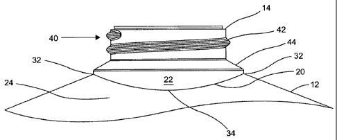
Figure 1 shows a lightweight blow moulded plastics container 10 embodying one
aspect of the invention. The container 10 comprises a body portion 12 and a
neck
portion 14. The body portion 12 defines a chamber 16 for storing liquid (e.g.
milk).
The neck portion 14 is mounted on and extends from the body portion 12 and has
an
CA 02725228 2010-10-05
WO 2010/043890 PCT/GB2009/051359
9
open passageway 18 therethrough which communicates with the chamber 16 and
through which the container 10 is filled with, and emptied of, liquid. As is
normal in
the art, the passageway 18 may by covered with a hermetic seal.
The neck portion 14 intersects the body portion 12 in a closed loop 20 with a
non-
planar profile. The closed loop 20 is located at the transition between the
substantially
cylindrical wall 22 at the base of the neck portion 14 and the upper part or
shoulders
24 of the body portion 12.
The non-planar profile of the closed loop 20 is best illustrated with
reference to Figure
4 which shows a standard saddle surface 30. The closed loop 20 lies on such a
surface
at a fixed distance from the central axis XX. The closed loop 20 has a pair of
maxima
32 and a pair of minima 34, and these are seen in Figure 2 and 3 disposed
equidistantly around the circumference of the cylindrical wall 22.
In the illustrated embodiment, the closed loop 20 has a substantially circular
footprint,
being bound by cylindrical wall 22.
The neck portion 14 may have a substantially cylindrical upper part 40 with a
screw
thread 42 for engaging a lid (not shown) with a corresponding screw thread.
The
cylindrical upper part 40 and cylindrical wall 22 at the base of the neck
portion 14 are
separated by a frusto-conical section 44, arranged such that the neck portion
is wider
at its base than at its free end. The cylindrical upper part 40, cylindrical
wall 22 and
frusto-conical section 44 are all centred on a common longitudinal axis. The
height of
the cylindrical wall 22 (in a direction parallel to the common longitudinal
axis) varies
in a circumferential direction around the periphery of the neck portion 14,
dependent
upon curvature of the closed loop 20 in a direction parallel to the common
longitudinal axis. The lower end of the cylindrical wall 22 defines the non-
planar
intersection with the shoulder region of the body portion 12.
It should be noted that the container 10 is of the kind configured to stand on
a planar
surface, e.g. on a trolley or refrigerator shelf. More particularly, the body
portion 12,
neck portion 14 and open passageway 18 have a common (central) longitudinal
axis,
CA 02725228 2010-10-05
WO 2010/043890 PCT/GB2009/051359
intended to be generally vertical during storage of the container (i.e. with
the rim of
the open passageway 18 presented generally horizontally). The closed loop 20
is
coaxial with said common longitudinal axis of the body portion 12, neck
portion 14
and open passageway 18. The concentricity of the body portion 12, neck portion
14,
5 open passageway 18 and closed loop 20 is desirable to avoid twisting forces
that
might otherwise occur during topload force testing.
The container may also be referred to as a "centre neck" container, by virtue
of the
open passageway being concentric with the central longitudinal axis of the
body
10 portion of the container. Such a configuration is particularly advantageous
in
reducing foaming effects during the filling of the container with liquid, e.g.
milk.
The container 10 is manufactured by blow moulding using an appropriately
shaped
mould tool. An example of a suitable tool is shown in Figure 5, wherein the
tool 50
includes a neck block 52, body block 54 and base block 56. The body block 54
and
base block 56 define a continuous cavity 58 in which the body portion 12 of
the
container 10 is formed. The neck block 52 defines a cavity 60 in which the
threaded
neck portion 14 of the container 10 is formed.
As is common in the art, the neck block 52 is provided with a neck insert 62
configured to define the desired shape and thread formation of the neck
portion 14.
Neck inserts of different internal configuration are interchangeable within
the neck
block 52. Similarly, the neck block 52 may be interchangeable with different
body
blocks 54.
It will be understood that the body portion 12 and neck portion 14 are
distinct parts of
the container 10, which are conventionally defined by distinct pieces of the
mould tool
50, i.e. the body block 54 and neck block 52, respectively, separated by a
split line 64
of the tool 50 (at the transition between the neck block 52 and the body block
54).
However, in preferred embodiments of the invention, the closed loop 20 is
below the
split line. More particularly, the cylindrical part 22 of the neck portion 14
is formed
below the split line 64, within the body block 54. Hence, the closed loop 20
is located
adjacent, yet below, what is commonly referred to as the `neck platform' of
the
CA 02725228 2010-10-05
WO 2010/043890 PCT/GB2009/051359
11
container (known conventionally as the part of the neck portion which meets
the
shoulders of the body portion). However, in this case, the cylindrical part is
effectively an intermediate formation between the neck platform and the
shoulders of
the body portion. In each case, it will be preferred if the closed loop and
associated
intermediate formation is formed in the body block 54, so that different
threaded
portions can be blow moulded therewith using different neck blocks 52.
The result is a strengthened container, which overcomes the conventional
requirement
for increased wall thickness between the neck and body portions in order to
overcome
structural weakness.
Figures 6a-6c illustrate respectively perspective, plan and front views of a
first plastics
container 110 embodying a second aspect of the invention, and Figures 9a and
9B
illustrate respectively plan and front views of a second plastics container
210
embodying the second aspect of the invention. The first and second plastics
containers 110, 210 have different capacities, with the first container 110
having a 1
pint capacity and the second container 210 having a 6 pint capacity.
Otherwise, the
first and second containers 110, 210 have many features in common, including a
body
120, 220 with a neck portion 124, 224 which intersects the rest of the body in
a closed
loop 126, 226 with a non-planar profile.
The body 120 of the first container 110 has an integral handle 130 defining an
aperture 132 (often referred to as the handle `eye') with a central axis AA
extending in
a first direction through the body 120. The central axis AA is parallel to the
direction
of separation of the two parts 134, 136 of the mould - shown schematically in
Figure
6b - in which the first container 110 is formed.
The body 120 projects a footprint 140 which in the present case is taken to be
the
outermost periphery visible in the plan view. The footprint 140 has a
longitudinal axis
BB extending in a second direction which is perpendicular to the first
direction. The
footprint 140 has a width which varies along its longitudinal axis BB, and is
greater in
a middle region 142 of the footprint 140 than at either longitudinal end 144
thereof.
In fact, the maximum width (Wmax) is in the middle region 142 and the minimum
CA 02725228 2010-10-05
WO 2010/043890 PCT/GB2009/051359
12
width (Wmin) is at either longitudinal end 144. The ratio of Wmax:Wmin is
about 5:1.
The footprint 140 has a substantially truncated-diamond shape, with the
longitudinal
ends 144 being present in place of one pair of corners along the longitudinal
axis BB.
The longitudinal ends 144 represent the opposed parallel sides of the
container 110,
with central axis AA parallel thereto. The internal angles are non-right
angles, i.e. at
the middle region the opposing internal angles are greater than 90 degrees.
The
footprint 140 is generally six-sided and is distinct from four-sided or square
footprints
known in the art, as well as known quasi-octagonal footprints defined by a
generally
square bodies having curved or truncated corner regions which themselves
define
diametrically opposing sides/surfaces.
The footprint 140 of the container 110 includes a peripheral step 150, which
is formed
by a vertical groove or rib 152 in the body 150. The rib 152 helps with
aligning
multiple containers 110 in a predetermined orientation relative to an external
datum,
such as a conveyor 160, as shown in Figure 7. In this way the containers 110
may be
arranged into a close packed array, for example when filling a standard
trolley shelf
170 as shown in Figure 8.
Figures 9a and 9b illustrate the body 220 of the second container 220 having
an
integral handle 230 defining an aperture 232 with a central axis A'A'
extending in a
first direction through the body 220. The body 220 has a footprint 240 which
is
visible in Figure 9a. The footprint 240 has a longitudinal axis B'B' extending
in a
second direction which is perpendicular to the first direction. The footprint
240 has a
width which varies along its length, and is greatest (Wmax) in a middle region
242,
and smallest (Wmin) at either longitudinal end 244. The ratio of Wmax:Wmin is
about 3:1. The footprint 240 has a substantially truncated-diamond shape; the
longitudinal ends 244 replacing two corners along the longitudinal axis B'B'
and
adding an additional two sides to the otherwise four-sided shape. The
footprint 240
includes a slight peripheral step 250 formed by a vertical rib 252 which in
the case of
container 210 is more for styling than alignment purposes. As shown in Figure
10,
multiple containers 210 are arranged in a close packed array, with adjacent
rows offset
by half a container length to fit the width of a standard trolley shelf 270.
CA 02725228 2010-10-05
WO 2010/043890 PCT/GB2009/051359
13
The containers described in respect of Figures 6 to 10 are preferably formed
by blow
moulding. Preferably, the mould tool is configured such that the longitudinal
axis of
the handle and longitudinal axis of the body are in line with one another
along a centre
split line of the tool (such that the handle is arranged at one corner of the
body). Put
another way, the mould tool is configured so that the mould split line is
arranged
corner to corner with respect to the body, with the middle region of the body
extending in the direction of opening of the tool (perpendicular to the split
line).
As with the embodiment of the Figures 1 to 3, the containers 110, 210 include
a centre
neck open passageway, which is useful in reducing foaming effects during
filling of
the container with liquid, e.g. milk. The neck and passageway are arranged
with the
same concentricity considerations (with respect to the central vertical axis
of the body)
as the embodiments of Figures 1 to 3, to reduce for adverse topload forces
during
testing.
A known plastics container has a substantially rectangular footprint, with two
corner
regions on each side of a notional centre line aligned with the longitudinal
axis, with
all four corner regions equidistant thereform. An example of such a known
footprint
is shown at 300 in Figure 11. Such a container may be of blow moulded
construction,
e.g. formed by blow moulding a parison 310 in a mould with two parts 320, 330
which separate along a notional centre line 340 (e.g. along the central
longitudinal
axis of the footprint of the container in Figure 11) when ejecting the
container from
the mould.
Figure 12 shows a modified mould tool 400, wherein the split line 440 of the
mould
tool pieces 420, 430 is arranged generally `corner to corner' of a footprint
of non-
rectangular diamond shape of the kind described above (i.e. effectively at 45
degrees
to that shown in Figure 11). Providing that the corners 460 arranged at 90
degrees to
the split line 400 are not excessively deep, it has been found that the
stretching/thinning effect on the parison 410 is likely to be less extreme
than with
conventional mould tools of the kind shown in Figure 11, resulting in more
even
distribution of plastic within the wall thickness.
CA 02725228 2010-10-05
WO 2010/043890 PCT/GB2009/051359
14
As can be seen, the central longitudinal axis of the footprint in Figure 12 is
aligned
with the split line 440 of the mould tool 400. Preferably, the handle eye of
the
container (not visible in Figure 12) is also aligned with the split line 440,
as would be
the case for the containers shown in Figures 6c and 9b.
The footprint defined by the mould tool 400 is generally diamond-shaped, being
six-
sided with two generally opposing longitudinal end surfaces 470 separated by
four
angled side surfaces 480. The footprint is non-rectangular and the internal
angles of
the footprint in the middle region are greater than the internal angles at the
longitudinal ends of the footprint. Hence, the width of the footprint is
greatest at the
middle region and smallest at either longitudinal end.