Note: Descriptions are shown in the official language in which they were submitted.
CA 02725890 2010-11-25
Specification
[Title of the Invention] Implant Body, Method of Manufacture of Same, and
Dental
Implant
[Technical Field]
[0001]
The present invention relates to an implant body fixed in a tightly attached
configuration to bone, for example, an implant body embedded in the bone of
the jaw
or the like when damage has occurred to the tooth root of a permanent tooth.
The
invention also relates to a method of manufacture for the implant body, and to
a dental
implant.
[Background Art]
[0002]
Conventionally, an implant body may be embedded into the bone and fixed in
a contact configuration for application as an artificial bone, a bone
attachment
material, a bone reinforcing material, or the like.
For example, when a tooth root of a permanent tooth is destroyed by tooth
decay or damage, a dental implant is used in which an implant body is inserted
into a
drill hole in the alveolar bone, and is fixed thereto. The dental implant is
generally
configured from an implant body that is fixed to the alveolar bone, and an
abutment
that is threadably attached to the implant body to thereby enable detachable
mounting
of an artificial dental crown.
[0003]
The material currently employed to configure the implant body is often pure
titanium. However since use of pure titanium entails the disadvantage of the
risk of
the occurrence of metal allergies or the attachment of bacteria, in recent
years,
ceramic materials that exhibit superior bio-affinity and mechanical strength
have been
examined as alternative materials adapted for an implant body. For example,
Patent
Literature 1 discusses several materials including a ceramic material as a
material for
an implant. Furthermore Patent Literature 1 discloses the chemical,
electrical,
mechanical, laser processing or the like to create surface roughness on the
surface of
the implant in order to impart biocompatibility.
1
CA 02725890 2010-11-25
[Citation List]
[Patent Literature]
[0004]
[Patent Literature 1] Japanese Patent Application Laid-Open No. 4046213
[Disclosure of the Invention]
[Problem to be Solved by the Invention]
[0005]
The following problems remain unsolved in the conventional technique.
In other words, in the technique disclosed in Patent Literature 1, although
the
bio compatibility is improved by roughening of the surface by the application
of a
mechanical process, laser process or the like to the surface of the implant,
simple
roughening is insufficient, and acquisition of improved bio-affinity and high
levels of
bone attachment is difficult. As a result, there is a need for an implant body
that is
provided with improved bio-affinity and that enables strong bone attachment,
and in
particular, there is a demand for an implant body that is formed by a ceramic
material
that has superior bio-affinity, mechanical strength, and the like.
[0006]
The present invention is proposed in light of the above problems, and has the
object of providing an implant body, a method of manufacture for the same, and
a
dental implant that enables improved bio-affinity and that enables strong bone
attachment.
[Means for Solving the Problem]
[0007]
The present invention adopts the following configuration in order to solve the
above problem. In other words, the implant body according to the present
invention
is an implant body that is fixed in a contact configuration to the bone, and
is
characterized in a configuration of a base material formed from zirconia, and
a surface
layer formed on the surface of the base material and having a lower hardness
than the
base material.
[0008]
Since the implant body includes the base material formed from zirconia, and
the surface layer formed on the surface of the base material and having a
lower
hardness than the base material, in addition to having superior mechanical
strength
2
CA 02725890 2010-11-25
due to the zirconia base material, the soft and flexible surface layer
functions as a
buffer layer to mitigate the difference in the degree of hardness between the
bone and
the base material, and therefore the soft surface further improves the bone
adhesion
characteristics.
[0009]
The implant body according to the present invention is characterized by the
foimation of a plurality of crack cavities on the surface layer. In other
words, since
the implant body forms a plurality of crack cavities on the surface layer,
rather than
simple roughening, the bone cells can enter into the crack cavities in the
surface layer.
When the bone cells enter, the contact surface area is greatly increased, and
a
cross-linking effect is obtained. Furthermore high bone adhesion
characteristics and
bone attachment are obtained.
[0010]
Furthermore the implant body according to the present invention is
characterized in that the hardness of the surface layer is less than or equal
to the
hardness of the bone. In other words, since the hardness of the surface layer
in the
implant body is less than or equal to the hardness of the bone, attachment of
bone
tissue is facilitated by the flexible surface which has the same hardness as
the bone or
is softer than the bone.
[0011]
Furthermore the surface layer of the implant body according to the present
invention is characterized in being formed by zirconia hydroxide. In other
words,
since the surface layer of the implant body is formed by zirconia hydroxide,
high bone
adhesion characteristics and an improved bio-affinity with bone tissue are
obtained by
a zirconia hydroxide surface layer. In other words, the zirconia hydroxide
surface
layer is thought to have an ion exchange action and strengthens the increase
in
calcium ions and migration of cells to thereby obtain a considerable
improvement in
bone adhesion.
[0012]
The dental implant according to the present invention is characterized by
provision of the implant body according to the present invention that is
inserted in a
drill hole in the alveolar bone that acts as the bone, and is fixed thereto.
That is to
say, since the dental implant is provided with the implant body according to
the
present invention that is inserted and fixed in a drill hole in the alveolar
bone, superior
3
CA 02725890 2010-11-25
mechanical strength is obtained, and high bone adhesion to the alveolar bone
is
obtained by the soft flexible surface layer.
[0013]
The method of manufacturing the implant body according to the present
invention is a manufacturing method for the implant body that is fixed in a
contact
configuration to the bone. The method is characterized by including a step of
forming a zirconia hydroxide surface layer having a lower hardness than the
base
material on the surface of the zirconia base material by irradiation of laser
light in air
including water vapor.
[0014]
In other words, in the method of manufacturing the implant body, since the
zirconia hydroxide surface layer having a lower hardness than the base
material is
formed on the surface of the base material formed from zirconia by irradiation
of laser
light in air including water vapor, formation of soft surface layer of
zirconia
hydroxide having a high adhesion is facilitated on the base material surface.
In other
words, the zirconia of the base material is irradiated with short-wavelength
laser light
such as solid-state laser light, and undergoes surface roughening by changing
the
surface configuration due to the high-energy laser light. In addition, the
water vapor
reacts with the zirconia to thereby enable formation of a hydroxide substance,
in other
words, a hydroxide (zirconium hydroxide) surface layer. Furthermore the
zirconia
hydroxide surface layer resulting from the manufacturing method enables a
reduction
in the level of hardness due to the production of a plurality of crack
cavities.
[0015]
The method of manufacturing of the implant body according to the present
invention is characterized in that the laser light is laser light that has a
fundamental
wave caused by an Nd:YAG laser or a YV04 laser. In other words, since the
method
of manufacturing of the implant body uses laser light having a fundamental
wave
caused by an Nd:YAG laser or a YV04 laser, a zirconium hydroxide surface layer
is
formed on the zirconium base material surface by short-wavelength high-energy
laser
light, and facilitates formation of a plurality of crack cavities.
[0016]
The manufacturing method for an implant body according to the present
invention is characterized in that the hardness of the surface layer is less
than or equal
to the hardness of the bone as a result of irradiation with the laser light.
In other
4
CA 02725890 2010-11-25
words, in the manufacturing method for an implant body, since the hardness of
the
surface layer is less than or equal to the hardness of the bone as a result of
irradiation
with the laser light, as shown above, a surface layer is obtained in which
attachment
of bone tissue is facilitated.
[Effect of the Invention]
[0017]
The present invention obtains the following effect.
In other words, since the implant body according to the present invention,
and the manufacturing method therefor, forms a surface layer that has a lower
hardness than the base material on the surface of the base material formed
from
zirconia, in addition to mechanical strength that is superior to the zirconia
base
material, the soft and flexible surface layer functions as a buffer layer to
mitigate the
difference in the degree of hardness between the bone and the base material,
and
therefore the soft surface further improves the bone adhesion characteristics.
Therefore the implant body obtains improved bio-affinity and high bone
attachment.
In particular, high bone attachment characteristics are obtained with respect
to
alveolar bone by application of the implant body of the dental implant that
inserts and
fixes the implant body to the drill hole in the alveolar bone.
[Brief Description of the Drawings]
Fig. 1 is a front view showing a dental implant according to a first
embodiment of an implant body, a method of manufacturing the same, and a
dental
implant according to the present invention.
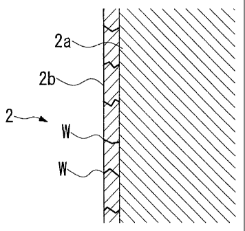
Fig. 2 is a schematic enlarged sectional view showing an implant body
according to the present invention.
Fig. 3 is a graph shows the results of infrared spectrophotometric analysis of
the surface according to a working example and a comparative example of an
implant
body, a method of manufacturing the same, and a dental implant according to
the
present invention.
Fig. 4 is an SEM image of the surface of the implant body according to a
working example of an implant body, a method of manufacturing the same, and a
dental implant according to the present invention.
Fig. 5 is an SEM image of the surface of the implant body according to a
working example of an implant body, a method of manufacturing the same, and a
dental implant according to the present invention.
CA 02725890 2010-11-25
Fig. 6 is an SEM image of the surface of the implant body according to a
working example of an implant body, a method of manufacturing the same, and a
dental implant according to the present invention.
Fig. 7 is an enlarged photographic image of the principal sectional portions
using an optical microscope 4 weeks after the insertion of an actual implant
body into
an experimental rat according to a comparative example of an implant body, a
method
of manufacturing the same, and a dental implant according to the present
invention.
Fig. 8 is an enlarged photographic image of the principal sectional portions
using an optical microscope 4 weeks after the insertion of an implant body
into an
experimental rat according to a comparative example of an implant body, a
method of
manufacturing the same, and a dental implant according to the present
invention.
Fig. 9 is an enlarged photographic image of the principal sectional portions
using an optical microscope 4 weeks after the insertion of an implant body
into an
experimental rat according to a working example of an implant body, a method
of
manufacturing the same, and a dental implant according to the present
invention.
Fig. 10 is an enlarged photographic image of the principal sectional portions
using an optical microscope 4 weeks after the insertion of an implant body
into an
experimental rat according to a working example of an implant body, a method
of
manufacturing the same, and a dental implant according to the present
invention.
Fig. 11 is an enlarged photographic image of the principal sectional portions
using an optical microscope 4 weeks after the insertion of an implant body
into an
experimental rat according to a comparative example of an implant body, a
method of
manufacturing the same, and a dental implant according to the present
invention.
Fig. 12 is an enlarged photographic image of the principal sectional portions
using an optical microscope 4 weeks after the insertion of an implant body
into an
experimental rat according to a working example of an implant body, a method
of
manufacturing the same, and a dental implant according to the present
invention.
[Best Mode for Carrying Out the Invention]
[0019]
Hereafter a first embodiment of the implant body, the method of
manufacturing the same, and the dental implant according to the present
invention
will be described below making reference to Fig. 1 and Fig. 2.
[0020]
6
CA 02725890 2010-11-25
The implant body 2 according to the present embodiment is an implant body
fixed in a contact configuration to the bone, and as shown in Fig. 1, is
applied to an
implant body for a dental implant 1 inserted and fixed to a drill hole in
alveolar bone
that acts as the bone described above.
The implant body 2 is formed substantially in a cylindrical shape with a tip
that has a gradually reducing external diameter towards a lower portion
(distal end).
The outer periphery of the implant body 2 forms as a male threaded portion 3.
The
male threaded portion 3 is formed by gradually varying the shape with respect
to the
axial direction of the implant body 2. The male threaded portion 3 is
configured as a
self-tapping threaded portion 3a in which the distal end is provided with an
engraved
groove on the thread, and thereby enables direct threadable engagement in the
drilled
hole of the alveolar bone.
[0021]
An abutment (not shown) can be fixed by a bonding means such as a
threaded structure to an upper portion of the implant body 2. For example, the
male
thread is formed on the lower portion of the abutment, and a female threaded
hole (not
shown) enabling threadable engagement with the male thread of the lower
portion of
the abutment is formed on the upper portion of the implant body 2.
[0022]
The implant body 2 as shown in Fig. 2 is configured from a base material 2a
formed from zirconia and a surface layer 2b formed on the surface of the base
material 2a from zirconia hydroxide having a hardness that is lower than the
base
material 2a.
A plurality of crack cavities W is formed on the surface layer 2b, and
therefore further reduces the surface hardness.
The hardness of the surface layer 2b is less than or equal to the hardness of
the alveolar bone. The hardness of the surface layer 2b in the present
embodiment is
of the level of 300 Hv in contrast to a Vickers hardness of the level of 500
Hv in
normal alveolar bone.
[0023]
Next, the method of manufacturing the implant body 2 of the dental implant
will be described.
7
CA 02725890 2010-11-25
Firstly, a base material 2a of the implant body 2 that has an outer
configuration including a male threaded portion 3 is prepared using zirconia
(zirconia
ceramic).
[0024]
Next, a surface layer 2b of zirconia hydroxide is formed on the surface of the
base material 2a by irradiating laser light in air containing moisture (in an
atmosphere
containing water vapor). The laser light that is employed at this time must be
high-energy laser light, and for example, laser light (fundamental wave)
produced by
a Nd:YAG laser or a YV04 laser which are solid-state lasers is used.
[0025]
When irradiating the laser light, a setting is adapted so that the hardness of
the surface layer 2b is less than or equal to the hardness of the alveolar
bone. In
other words, since the Vickers hardness of alveolar bone is normally of the
level of
500 Hv, in the present embodiment, the output or the like of the Nd:YAG laser
light or
the YV04 laser light is set and irradiated so that a surface layer having a
hardness of
substantially 300 By is formed. A blackened surface layer 2b is formed by
irradiation of laser light.
[0026]
Since the implant body 2 and the dental implant 1 provided with the implant
body 2 according to the present embodiment are provided with a base material
2a that
is formed from zirconia and a surface layer 2b that has a lower hardness than
the base
material 2a and is formed on the surface of the base material 2a, in addition
to
mechanical strength that is superior to that of the zirconia base material 2a,
the soft
and flexible surface layer 2b functions as a buffer layer to mitigate the
difference in
the degree of hardness between the bone such as alveolar bone and the base
material
2a. Furthermore
the bone adhesion characteristics are improved by the soft surface.
In particular, since a plurality of crack cavities W is formed on the surface
layer 2b, rather than simple roughening, the bone cells can enter into the
crack cavity
W of the surface layer 2b. Entry of the bone cells causes a considerable
increase in
the contact surface area, obtains a cross-linking effect, and enables high
bone
adhesion and bone attachment.
[0027]
In other words, an implant having a surface formed from a dense
high-hardness ceramic material as in the conventional example exhibits an
upper limit
8
CA 02725890 2010-11-25
to improvement in bone adhesion that is enabled by simply roughening the
surface.
However in the implant body 2 according to the present embodiment, the
hardness of
the surface layer 2b is reduced by the plurality of crack cavities W formed in
the
surface and the bone cells can enter into an inner portion through the crack
cavities W.
Thus when the bone cells enter, high bone adhesion and bone attachment are
enabled
due to the increase in the contact surface area and the cross-linking effect.
[0028]
Since the hardness of the surface layer 2b is less than or equal to the
hardness
of the bone such as alveolar bone, a hardness that is equivalent to bone such
as
alveolar bone or a surface that is softer and more flexible than bone such as
alveolar
bone facilitates improved close adhesion of bone tissue.
Furthermore, since the surface layer 2b is formed from zirconia hydroxide,
superior bio-affinity and high bone attachment to bone tissue are enabled by
the
zirconia hydroxide of the surface layer 2b. In other words, the zirconia
hydroxide of
the surface layer 2b has an ion exchange effect which is thought to increase
calcium
ions and strengthen the growth of cells, and cause a considerable improvement
in
bone adhesion.
[0029]
Since the method of manufacturing the implant body 2 forms a surface layer
2b of zirconia hydroxide having a lower hardness than the base material 2a on
the
surface of the zirconia base material 2a by irradiating laser light in air
containing
moisture, formation of a soft zirconia hydroxide surface layer 2b having high
adhesion characteristics on the surface of the base material 2a can be
facilitated. In
other words, the surface configuration of the zirconia of the base material 2a
that is
irradiated with short-wave laser light such as a solid-state laser or the like
undergoes
roughening due to high energy laser light. However in addition, the zirconia
reacts
with the moisture to form a surface layer 2b of a hydroxide compound, in other
words,
a hydroxide (zirconia hydroxide).
[0030]
The surface layer 2b of zirconia hydroxide formed by the method of
manufacture has a reduced hardness due to the production of a plurality of
crack
cavities W.
In particular, laser light having a fundamental wave resulting from a Nd:YAG
laser or a YV04 laser produces short-wavelength high-energy laser light and
therefore
9
CA 02725890 2010-11-25
forms a zirconia hydroxide surface layer 2b on the surface of the zirconia
base
material 2a and facilitates formation of the plurality of crack cavities W.
[Embodiment 1]
[0031]
Next, the implant body, a method of manufacture for the implant body, and a
dental implant according to the present invention will be described in detail
by
working examples making reference to Fig. 3 to Fig. 12.
[0032]
Firstly a non-processed zirconia implant body without a hydroxide surface
layer 2b processed using laser light as described above and formed from an
unmodified zirconia base material 2a for the purposes of comparison, and a
zirconia
implant body processed by laser to form a hydroxide zirconia surface layer 2b
using
the laser light as described above as a working example were prepared. The
irradiation laser light used an Nd:YAG laser as a fundamental wave.
[0033]
The results obtained by application of infrared spectrophotometric analysis to
the comparative example and the working example are shown in Fig. 3. The
curved
lines showing the comparative example and the working example in the figure
are
expressed with a vertical deviation for ease of comparison.
The result of this analysis show that the peak (falling portion of the curve)
of
the hydroxide compound (OH group) in the working example is observed in the
portion enclosed by the circle in the figure, and that therefore zirconia
hydroxide is
formed as a hydroxide compound. In contrast, the comparative example of
non-processed zirconia does not exhibit a hydroxide compound peak. Thus in the
present working example, it is shown that a zirconia hydroxide surface layer
2b is
formed by irradiation of laser light as described above on the surface of the
zirconia
base material 2a.
[0034]
Next, the results of a hardness measurement using a nano-hardness tester
(DLC film hardness measurement) are shown. A nano-hardness tester is a
measurement apparatus that measures the load and the hardness, and is set to
an
engraved depth of 1
[0035]
CA 02725890 2010-11-25
The results of two measurements of the Vickers hardness of the comparative
example that is only formed from a zirconia base material 2a are 998 Hv and
1129 Hv.
In contrast, the working example that forms a zirconia hydroxide surface layer
2b had
a Vickers hardness of 336 Hv and 328 Hv. In other words, the hardness of the
surface of the working example that forms a zirconia hydroxide surface layer
2b is
clearly lower than the comparative example that is only formed from a zirconia
base
material 2a, and the surface is also soft in comparison to alveolar bone which
normally has a hardness of the level of 500 Hv.
[0036]
The surface layer 2b of the implant body 2 of the working examples is shown
by SEM images captured using an electron microscope at different
magnifications as
shown in Fig. 4 to Fig. 6. As shown by these SEM images, a plurality of crack
cavities W is produced in the surface layer 2b.
[0037]
Next, the results observed in relation to the state four weeks after actually
embedding the implant body in an experimental rat are shown in Fig. 7 to Fig.
12.
An implant body having a diameter of 1.6 mm and a length of 7.0 mm was
used and embedded into the tibia of a four-week old SD rat. The implant body
used
in the present working example formed a surface layer due to irradiation with
YV04
laser light.
[0038]
Firstly, Fig. 7, Fig. 8 and Fig. 11 are enlarged photographic images captured
with an optical microscope of the principal sectional components when using
the
comparative example which only includes the zirconia base material 2a. The
uniformly black section in the enlarged photographic images represents the
implant
body, and the partially black portion in the periphery thereof is a bone
component that
is dyed with toluidine blue (the original photographic images are color
images, and
the bone components are expressed as blue). In contrast, Fig. 9, Fig. 10 and
Fig. 12
are enlarged photographic images captured using an optical microscope of the
principal sectional components when using the working example which forms a
zirconia hydroxide surface layer 2b. The magnifications used in the images are
as
follows: Fig. 7 is 10 times, Fig. 8 is 40 times, Fig. 9 is 10 times, Fig. 10
is 40 times,
Fig. 11 is 150 times, and Fig. 12 is 50 times.
[0039]
11
CA 02725890 2010-11-25
In the comparative example and the working example, the results of
calculating the contact ratio between the surface of the implant body and the
bone
tissue results in a contact ratio for the comparative example of 27.9% in
contrast to a
contact ratio for the embodiment of 64.8% which therefore represents a
considerable
improvement in the contact ratio.
In this manner, in comparison to using the implant body according to the
comparative example, a large amount of newly formed bone component is observed
in
the periphery of the implant body when using the implant body according to the
working example, and it is shown that superior bio-affinity and high bone
attachment
are obtained. The regenerated bone in the periphery of the implant body comes
into
direct contact with the implant body and therefore achieves so-called
ossointegration.
[0040]
The technical scope of the present invention is not limited to the above
embodiments and various modifications may be added without departing from the
spirit of the present invention.
[0041]
For example, in the present embodiment, although laser irradiation was
performed using laser light produced by an Nd:YAG laser or a YV04 laser,
another
type of laser light may be employed to the degree that it is high-energy laser
light that
enables formation of a zirconia hydroxide surface layer 2b by hydroxide
formation on
the surface of the zirconia base material 2a. For example, laser light from
another
solid-state laser or laser light from a harmonic wave.
[0042]
In the present embodiment, the implant body according to the present
invention is applied as an implant body for a dental implant forming an
artificial tooth
root fixed by insertion into a drill hole in the alveolar bone. However the
implant
body may be applied as an implant body that is embedded or the like into bone
in
another region and fixed in a state of contact. For example, the implant body
according to the present invention may be applied as artificial bone or a bone
filling
material in relation to damage to bone resulting from fracture or removal of
benign
tumors, or to supplement cartilage that is removed due to lumbar vertebrae
surgery.
Furthermore the implant body according to the present invention may be
employed in
relation to a member for an artificial joint, a bone attachment material used
to fix
positions of bone fracture, or a vertebral fixing apparatus.
12
CA 02725890 2010-11-25
[Description of the Reference Numerals]
1 DENTAL IMPLANT
2 IMPLANT BODY
2a BASE MATERIAL
2b SURFACE LAYER
W CRACK CAVITY
13