Note: Descriptions are shown in the official language in which they were submitted.
CA 02726191 2010-12-21
Attorney Docket No. 105196.014100
REDUNDANT SUMP PUMP SYSTEM
BACKGROUND
[0001] Sump pumps are typically used to extract a fluid from a basement, a
container, or a
vessel, such as water from a basement of a house or water from a bilge of a
boat. Typically, the
sump pump is activated based on a fluid level in the basement, container, or
vessel.
[0002] In order to prevent flooding, the sump pump must be able to extract the
fluid from the
basement, container, or vessel at a higher flow rate than the fluid entering
the vessel. The sump
pump generally must be designed for the highest expected incoming flow rate
into the basement,
container, or vessel. As a result, conventional sump pumps include a
relatively powerful motor
that often requires a higher power consumption than may be necessary. With
conventional sump
pumps, if the motor fails, there is no backup option and flooding occurs.
SUMMARY
[0003] Some embodiments of the invention a sump pump system that pumps fluid.
The
system can include a base with one or more inlets and one or more outlets. The
system can also
include a first cartridge coupled to the base and removable from the base. The
first cartridge can
include a first electric motor. The system can further include a second
cartridge coupled to the
base and removable from the base. The second cartridge can include a second
electric motor.
The first cartridge and/or the second cartridge can be capable of operating at
any given time in
order to propel fluid from the inlets to the outlets. In some embodiments, the
sump pump system
can include one or more cartridges. The cartridges can be removable from the
base without
removing an outlet conduit system and without interrupting electrical
communication between a
power supply and an electric motor in the cartridge. In some embodiments, the
sump pump
system can include a gasket with a flap coupled to the cartridge. The flap can
at least partially
cover one or more of the outlets.
DESCRIPTION OF THE DRAWINGS
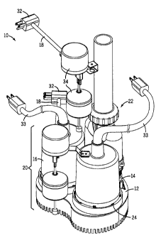
[0004] FIG. 1 is a perspective view of a sump pump system according to one
embodiment of
the invention.
PHX 329,131,361v1 12-23-09 1
CA 02726191 2010-12-21
Attorney Docket No. 105196.014100
[0005] FIG. 2 is an exploded view of the sump pump system of FIG. 1.
[0006] FIG. 3 is a bottom view of the sump pump system of FIG. 1 with a
collector removed.
[0007] FIG. 4 is a top view of the sump pump system of FIG. 1 with a cartridge
removed.
[0008] FIG. 5A is a perspective bottom view of a cartridge according to one
embodiment of
the invention.
[0009] FIG. 5B is an exploded view of the cartridge of FIG. 5A.
[0010] FIG. 6 is an exploded view of an outlet conduit system according to one
embodiment
of the invention.
[0011] FIG. 7 is a perspective view of a sump pump system according to another
embodiment of the invention.
[0012] FIG. 8 is an exploded view of the sump pump system of FIG. 7.
[0013] FIG. 9 is a perspective view of a cartridge for use with the sump pump
system of FIG.
7.
[0014] FIG. 10 is a top view of the sump pump system of FIG. 7.
[0015] FIG. 11 is a bottom view of the sump pump system of FIG. 7 with a
collector
removed.
[0016] FIG. 12 is a perspective view of a collector according to one
embodiment of the
invention.
DETAILED DESCRIPTION
[0017] Before any embodiments of the invention are explained in detail, it is
to be
understood that the invention is not limited in its application to the details
of construction and the
arrangement of components set forth in the following description or
illustrated in the following
drawings. The invention is capable of other embodiments and of being practiced
or of being
PHX 329,131,361v1 12-23-09 2
CA 02726191 2010-12-21
Attorney Docket No. 105196.014100
carried out in various ways. Also, it is to be understood that the phraseology
and terminology
used herein is for the purpose of description and should not be regarded as
limiting. The use of
"including," "comprising," or "having" and variations thereof herein is meant
to encompass the
items listed thereafter and equivalents thereof as well as additional items.
Unless specified or
limited otherwise, the terms "mounted," "connected," "supported," and
"coupled" and variations
thereof are used broadly and encompass both direct and indirect mountings,
connections,
supports, and couplings. Further, "connected" and "coupled" are not restricted
to physical or
mechanical connections or couplings.
[0018] The following discussion is presented to enable a person skilled in the
art to make and
use embodiments of the invention. Various modifications to the illustrated
embodiments will be
readily apparent to those skilled in the art, and the generic principles
herein can be applied to
other embodiments and applications without departing from embodiments of the
invention.
Thus, embodiments of the invention are not intended to be limited to
embodiments shown, but
are to be accorded the widest scope consistent with the principles and
features disclosed herein.
The following detailed description is to be read with reference to the
figures, in which like
elements in different figures have like reference numerals. The figures, which
are not
necessarily to scale, depict selected embodiments and are not intended to
limit the scope of
embodiments of the invention. Skilled artisans will recognize the examples
provided herein have
many useful alternatives and fall within the scope of embodiments of the
invention.
[0019] FIG. 1 illustrates a sump pump system 10 according to one embodiment of
the
invention. The sump pump system 10 can include a base 12, a first cartridge
14, a second
cartridge 16, a first power cord 18, a first float switch 20, and an outlet
conduit system 22. In
some embodiments, the first cartridge 14 and the second cartridge 16 can be
coupled to the base
12 using a quick connect device 24. As shown in FIG. 2, the first cartridge 14
and the second
cartridge 16 can each include a housing 26, an electric motor 28, and an
impeller 30.
[0020] In some embodiments, the first power cord 18 can include a switchplug
32. The first
float switch 20 can operate the switchplug 32 by selectively enabling or
interrupting a current
flow through the switchplug 32 depending on a position of the first float
switch 20. A second
power cord 33 can be coupled to the switchplug 32 and at least one of the
first cartridge 14 and
PHX 329,131,361v1 12-23-09 3
CA 02726191 2010-12-21
Attorney Docket No. 105196.014100
the second cartridge 16. The second power cord 33 can provide the current flow
from the
switchplug 32 to the first cartridge 14 and/or the second cartridge 16. In
some embodiments, the
first cartridge 14 and the second cartridge 16 have each individual power
supplies. In other
embodiments, the first power cord 18, the first float switch 20, and/or the
second power cord 33
can provide power to both electric motors 28.
[0021] In some embodiments, the sump pump system 10 can include a second float
switch
34. The second float switch 34 can include the first power cord 18 and/or the
second power cord
33. In some embodiments, the first float switch 20 and/or the second float
switch 34 can include
a relay. The first float switch 20 can operate the first cartridge 14, while
the second float switch
34 can operate the second cartridge 16. The first cartridge 14 and/or the
second cartridge 16 can
pump the fluid out of a basement, container, or vessel. In some embodiments,
the first float
switch 20 can be operated by a first fluid level in the basement, container,
or vessel and the first
cartridge 14 can be activated. In some embodiments, the second float switch 34
can be operated
by a second fluid level to activate the second cartridge 16. In some
embodiments, the second
float switch 34 can be positioned above the first float switch 20 resulting in
the second fluid level
being higher than the first fluid level. For example, if the sump pump system
10 is used to
extract water from the vessel, the first float switch 20 can be engaged by a
water level inside the
vessel and the first cartridge 14 can be activated to extract water from the
vessel. If the first
cartridge 14 fails or if the first cartridge 14 extracts a smaller flow rate
than an incoming flow
rate into the vessel, the water level inside the vessel will rise. If the
water level engages the
second float switch 34, the second cartridge 16 can be activated. As a result,
the second
cartridge 16 can support the pumping action of the first cartridge 14 and/or
can act as a backup
system for the first cartridge 14. In some embodiments, only the first
cartridge 14 is activated
under normal operating conditions and the second cartridge 16 is only
activated during an
abnormal event, such as an unusually high flow rate and/or a failure of the
first cartridge 14.
Once a fluid level inside the vessel has dropped below a certain threshold,
the first float switch
20 and/or the second float switch 34 can disengage to shut down the respective
electric motor 28.
[0022] FIG. 2 illustrates the internal components of the sump pump system 10
according to
one embodiment of the invention. The electric motor 28 can include a rotor 36
and a stator 38.
The rotor 36 can include a shaft 40 to which the impeller 30 can be coupled.
The electric motor
PHX 329,131,361 v1 12-23-09 4
CA 02726191 2010-12-21
Attorney Docket No. 105196.014100
28 can be enclosed by the housing 26, which can include a latch 42 and a
protrusion 44. In some
embodiments, the protrusion 44 can be threaded. The protrusion 44 can be used
to connect the
power cord 33 to the first cartridge 14 and/or the second cartridge 16. A
connector (not shown)
from the power cord 33 can be coupled to the protrusion 44 to supply power to
the electric motor
28. The protrusion 44 can be used to make the connection watertight. In some
embodiments, the
threads can help prevent an accidental removal of the connector.
[0023] In some embodiments, the base 12 can include a fitting 46, which can be
used to
couple the housing 26 to the base 12. In some embodiments, the latch 42 can
engage a ridge 48
located on the fitting 46 to form the quick connect device 24. Other
embodiments can include
another suitable quick connect device 24. An O-ring 50 can seal the connection
between the
base 12 and the housing 26 in order to substantially prevent leakage of the
quick connect device
24. In some embodiments, the base 12 can further include a sidewall 52 and one
or more outlets
54. The sidewall 52 can include openings 56 forming an inflow 58 into the sump
pump system
10. In some embodiments, the first cartridge 14 and the second cartridge 16
can propel the fluid
from the inflow 58 to the outlets 54.
[0024] As shown in FIG. 2, the sump pump system 10 can include a first
collector 60 and a
second collector 62 for the first cartridge 14 and the second cartridge 16,
respectively. In some
embodiments, the first collector 60 and the second collector 62 can be coupled
to a bottom of the
base 12 using screws 64. In some embodiments, the sidewall 52 can be higher
than the first
collector 60 and the second collector 62. The first collector 60 and the
second collector 62 can
direct fluid from the impeller 30 to the outlets 54. In some embodiments, the
first collector 60
and the second collector 62 can help route fluid from the inflow 58 to the
outlets 54.
[0025] FIG. 3 illustrates the bottom of the sump pump system 10 according to
one
embodiment of the invention with the second collector 62 removed. The sidewall
52 can enclose
an inner surface 66 of the base 12. In some embodiments, the first collector
60 and/or the second
collector 62 can be coupled to the inner surface 66. In some embodiments, the
base 12 can
include a through hole 68 and a contoured passage 70. The through hole 68 can
be sized to
receive the impeller 30 through the base 12. As a result, the impeller 30 can
remain attached to
the first cartridge 14 or the second cartridge 16 during installation and/or
removal. The first
PHX 329,131, 361 v1 12-23-09 5
CA 02726191 2010-12-21
Attorney Docket No. 105196.014100
cartridge 14 and/or the second cartridge 16 can be coupled to an outer surface
of the base 12,
while the impeller 30 can be positioned adjacent to the inner surface 66.
[0026] In some embodiments, the shape of the contoured passage 70 can
correspond to the
shape of the first collector 60 and/or the second collector 62. The contoured
passage 70 can help
seal the connection between each collector 60, 62 and the base 12. In some
embodiments, the
contoured passage 70 can enclose the outlet 54. In one embodiment, as shown in
FIG. 3, the
base 12 can be kidney-shaped.
[0027] In some embodiments, as shown in FIGS. 2 and 3, the impeller 30 can
include two or
more blades 72. The blades 72 can help draw the fluid through an aperture 74,
which can be
located on each one of the first collector 60 and the second collector 62. In
some embodiments,
the aperture 74 can be centrally aligned with the shaft 40 (as shown in FIG.
2). The fluid
entering the sump pump system 10 through the inlet 58 can flow into either the
first collector 60
or the second collector 62 through the aperture 74 before being routed to the
outlet 54.
[0028] FIG. 4 illustrates the top of the sump pump system 10 according to one
embodiment
of the invention with the second cartridge 16 removed. The housing 26 can
include rails 76 or
other suitable fixtures to allow attachment of the first float switch 20
and/or the second float
switch 34. In some embodiments, the outlet conduit system 22 can merge flow
from the outlets
54 into a common outlet 80.
[0029] FIG. 5A illustrates the bottom of the first cartridge 14 and/or the
second cartridge 16
according to one embodiment of the invention. In some embodiments, the first
cartridge 14 and
the second cartridge 16 can each include the housing 26, the impeller 30, and
a bottom plate 82.
The bottom plate 82 can act as a lid for the housing 26. In some embodiments,
the housing 26
can include a fluid (e.g., oil or other lubricants). The housing 26 can be
filled with the fluid
through a filler hole 83. In some embodiments, the housing 26 can include the
latch 42, the
protrusion 44, and a groove 84. The O-ring 50 (as shown in FIG. 5B) can be
coupled to the
housing 26 using the groove 84. The electric motor 28 can be enclosed by the
housing 26 and
the bottom plate 82. In some embodiments, the impeller 30 can be positioned
adjacent to the
bottom plate 82.
PHX 329,131,361v1 12-23-09 6
CA 02726191 2010-12-21
Attorney Docket No. 105196.014100
[0030] In some embodiments, the first cartridge 14 and the second cartridge 16
can be
substantially identical. In other embodiments, the first cartridge 14 and the
second cartridge 16
can include different sizes or types of electric motors 28. In one embodiment,
the first cartridge
14 can include an AC electric motor and the second cartridge 16 can include a
DC electric motor.
Accordingly, in some embodiments, the first cartridge 14 can be powered by an
alternating
current (AC) power source and the second cartridge 16 can be powered by a
direct current (DC)
power source. For example, the first cartridge 14 can be powered by a building
or mains power
supply and the second cartridge 16 can be powered by a battery. If the mains
power is lost, the
second cartridge 16 can be activated.
[00311 In some embodiments, each electric motor 28 of the sump pump system 10
can be
less powerful and/or consume less energy than a conventional sump pump
including a single
motor. While a conventional sump pump with a single motor must be designed to
fulfill the
expected highest flow rate, the electric motors 28 can be designed to pump an
expected average
flow rate. As a result, the electric motors 28 can be more compact, generate
less heat, and/or can
draw less current from the power source. In some embodiments, only if the
expected average
flow rate is exceeded, will the first cartridge 14 and the second cartridge 16
operate at the same
time in order to satisfy the higher flow demand.
[0032] FIG. SB illustrates the internal components of the first cartridge 14
and/or the second
cartridge 16 according to one embodiment of the invention. Each one of the
first cartridge 14
and the second cartridge 16 can include the housing 26, the O-ring 50, the
stator 38, the bottom
plate 82 (as shown in FIG. 5A), the rotor 36, the shaft 40, and the impeller
30. The first cartridge
14 and the second cartridge 16 can each further include a gasket 86 and a seal
88. The stator 38
can be coupled to the bottom plate 82. The stator 38 can include a hole 90,
which can receive the
shaft 40. In some embodiments, the hole 90 can serve as a bearing for the
rotor 36. The gasket
86 can seal the housing 26 to the bottom plate 82. In some embodiments,
friction between the
gasket 86 and the housing 26 can hold the bottom plate 82 in position.
[0033] The bottom plate 82 can include an opening 92 and a cylinder 94. The
cylinder 94
can hold the rotor 36 in position with respect to the stator 38. In some
embodiments, the cylinder
94 can house a bearing for the shaft 40. The shaft 40 can extend through the
opening 92 and the
PHX 329,131, 361 v1 12-23-09 7
CA 02726191 2010-12-21
Attorney Docket No. 105196.014100
seal 88 can make the connection between the shaft 40 and the bottom plate 82
waterproof. The
impeller 30 can be coupled to the shaft 40, which can extend beyond the bottom
plate 82.
[0034] In some embodiments, the sump pump system 10 can include an automatic
plug and
pump feature. The first cartridge 14 and/or the second cartridge 16 can be
replaced without
removing any piping or disassembling the sump pump system 10. In some
embodiments, the
quick connect device 24 can facilitate the installation and/or the removal of
the first cartridge 14
or the second cartridge 16. For example, if the first cartridge 14 is not
operating, the quick
connect device 24 can be used to disengage and the first cartridge 14 together
with the first float
switch 20 (which can be attached to the first cartridge 14 by the rail 76) can
be removed from the
sump pump system 10. The first float switch 20 can be reattached to the new
"cartridge" before
installing the new cartridge as the first cartridge 14 on the sump pump system
10. As a result,
the downtime of the sump pump system 10 before the sump pump system 10 can be
put back
into service after a breakdown can be substantially reduced.
[0035] FIG. 6 illustrates the outlet conduit system 22 according to one
embodiment of the
invention. The outlet conduit system 22 can include adapters 94, a junction
96, a ring seal 98, a
cap 100, and a pipe 102. The junction 96 can include pipe sections 104. In
some embodiments,
one adapter 94 and one pipe section 104 are provided for each outlet 54. The
junction 96 can
merge the fluid from the outlets 54 into the common outlet 80.
[0036] In some embodiments, the adapters 94 can include threads 106 and a flow
restrictor
108. The threads 106 can be used to couple the adapters 94 to the base 12. The
flow restrictor
108 can prevent a fluid from exiting the outlet conduit system 22 through the
outlets 54. In some
embodiments, the flow restrictor 108 can prevent fluid flow from one of the
outlets 54 to
another. In some embodiments, the flow restrictor 108 can help direct fluid
flow toward the
common outlet 80.
[0037] In some embodiments, the junction 96 can be manufactured as an integral
part. The
junction 96 can include an eye 110. In some embodiments, the adapters 94 can
be screwed into
the base 12 and the junction 96 can be plugged onto the adapters 94. The eye
110 can be used to
couple the junction 96 to the base 12 with a fastener. The pipe 102 can be
coupled to the
PHX 329,131, 361 v1 12-23-09 8
CA 02726191 2010-12-21
Attorney Docket No. 105 196.014 100
junction 96 with the ring seal 98 and the cap 100. The pipe 102 can be part of
an outlet piping
system routing the pumped fluid away from the sump pump system 10.
[0038] FIG. 7 illustrates a sump pump system 200 according to another
embodiment of the
invention. The sump pump system 200 can include a base 212, a first cartridge
214, a second
cartridge 216, and a cover 218. The base 212 can include openings 220, which
can act as an
inflow 222 to the sump pump system 200. In some embodiments, the openings 220
can be
positioned along a substantially straight portion of the base 212.
[0039] In some embodiments, the cover 218 can engage the base 212 to form an
enclosure.
The first cartridge 214 and the second cartridge 216 can be positioned inside
the enclosure. In
some embodiments, the first cartridge 214 and the second cartridge 216 can
each be coupled to
the cover 218 using a nut 224. In some embodiments, the cover 218 can include
a common
outlet 226.
[0040] FIG. 8 illustrates the internal components of the sump pump system 200
according to
one embodiment of the invention. In some embodiments, each one of the first
cartridge 214 and
the second cartridge 216 can include a lid 228, a gland 230, a housing 232, an
electric motor 234,
a disc 236, a gasket 238, an impeller 240, and a collector 242. The base 212
can include a
sidewall 244, apertures 246, and outlets 248. Each aperture 246 can be sized
to receive one of
the impellers 240. In some embodiments, the base 212 can include ridges 249,
each of which
can be positioned adjacent to each aperture 246. In some embodiments, the
ridge 249 can help
align the first cartridge 214 and/or the second cartridge 216 onto the base
212.
[0041] In some embodiments, the first cartridge 214 and the second cartridge
216 can each
include the lid 228, the housing 232, the electric motor 234, the disc 236,
the gasket 238, and the
impeller 240. The housing 232 can enclose the electric motor 234. A shaft 250
of the electric
motor 234 can be received by the housing 232. The shaft 250 can extend through
the housing
232, the disc 236, the gasket 238, and the base 212. The impeller 240 can be
coupled to the shaft
250. In some embodiments, the gasket 238 can include a flap 252. In some
embodiments, the
flap 252 can extend substantially outward and can at least partially cover one
of the outlets 248.
PHX 329,131, 361 v1 12-23-09 9
CA 02726191 2010-12-21
Attorney Docket No. 105196.014100
[0042] In some embodiments, the first cartridge 214 can be activated to pump
the fluid. The
impeller 240 of the first cartridge 214 can draw the fluid through the inflow
222 into the
collector 242, which can route the fluid toward the outlet 248. The flap 252
can bend upward
enabling the fluid to fill the enclosure inside the cover 218. The first
cartridge 214 and the
second cartridge 216 can come into contact with the pumped fluid. If the
second cartridge 216 is
not activated, the flap 252 for the second cartridge 216 can prevent the fluid
from leaving the
enclosure so that the enclosure can be filled with the fluid until the common
outlet 226 is
reached. Additional conduits can be attached to the common outlet 226 in order
to route the
fluid to a desired location.
[0043] In some embodiments, the first cartridge 214 and/or the second
cartridge 216 can be
coupled to the cover 218. Each gland 230 can be aligned with an aperture 254
of the cover 218
and can be fixedly coupled to the cover 218. In some embodiments, the gland
230 can be welded
to the cover 218. Each housing 232 can be inserted through one gland 230 and
one aperture 254.
Each housing 232 can be substantially sealed except for an upper portion 256.
Each lid 228 can
be coupled to the upper portion 256 of each housing 232 and/or each gland 230.
In some
embodiments, the gland 230 can be threaded to engage the nut 224 in order to
couple the first
cartridge 214 or the second cartridge 216 to the sump pump system 200. In some
embodiments,
tightening the nut 224 can seal the upper portion 256 with respect to the lid
228 and/or the gland
230.
[0044] FIG. 9 illustrates the first cartridge 214 and/or the second cartridge
216 according to
one embodiment of the invention. The first cartridge 214 and the second
cartridge 216 can each
include the lid 228, the nut 224, the housing 232, the disc 236, the gasket
238, and the impeller
240. The lid 228 can include a protrusion 258, which, in some embodiments, can
be internally
threaded. In some embodiments, the lid 228 can further include a projection
260. The projection
260 can be used to couple the first float switch 20 and/or the second float
switch 34 to the first
cartridge 214 and/or the second cartridge 216.
[0045] In some embodiments, the disc 236 and the gasket 238 can be coupled to
a lower
portion 262 of the housing 232. In some embodiments, the disc 236 can be
larger than the
aperture 246 (as shown in FIG. 8) of the base 212 to support the gasket 238 in
order to seal the
PHX 329,131,361v1 12-23-09 10
CA 02726191 2010-12-21
Attorney Docket No. 105196.014100
base 212 to the first cartridge 214 or the second cartridge 216. In some
embodiments, the disc
236 can prevent leaking between the base 212 and the cartridge 214, 216 even
if the flap 252 is
moving (e.g., bending upward and/or downward).
[0046] FIG. 10 is the top of an assembled sump pump system 200 according to
one
embodiment of the invention. The lids 228 can each include an electrical
connector 264 to
supply power to each electric motor 234. In some embodiments, the electrical
connector 264 can
be positioned within the protrusion 258 to which the second power cord 33 can
be coupled. In
some embodiments, the protrusion 258 can be used to protect the electrical
connector 264 from
fluid.
[0047] In some embodiments, the first cartridge 214 and the second cartridge
216 can each
be associated with one outlet 248. The fluid pumped by the sump pump system
200 coming
from one outlet 248 can bend one flap 252 upward so that fluid can pass into
the enclosure
formed by the base 212 and the cover 218. In some embodiments, the other flap
252 can help
prevent fluid from exiting the enclosure through the other outlet 248. As a
result, the flaps 252
can help direct fluid flow from each outlet 248 to the common outlet 226. In
some
embodiments, a piping system from the outlets 248 to the common outlet 226 may
not be
necessary.
[0048] FIG. 11 illustrates the bottom of the sump pump system 200 according to
one
embodiment of the invention with one of the collectors 242 removed. The
impeller 240 can
include blades 266. The collector 242 can include an aperture 268. In some
embodiments, the
aperture 268 can be in fluid communication with the inflow 222 and one outlet
248.
[0049] FIG. 12 illustrates a collector 242 according to one embodiment of the
invention. The
collector 242 can include a chamber 270, which can be sized to enclose the
impeller 240. The
chamber 270 can be in fluid communication with a channel 272, which can enable
fluid
communication between the aperture 268 and the outlet 248. In some
embodiments, the channel
272 can include a sloped portion 274. The sloped portion 274 can increase the
volume of the
channel 272 adjacent to the outlet 248. As a result, the sloped portion 274
can direct fluid flow
toward the outlet 248. In other embodiments, the sloped portion 274 can
decrease a volume of
PHX 329,131,361v1 12-23-09 11
CA 02726191 2010-12-21
Attorney Docket No. 105196.014100
the channel 272 in order to direct the fluid toward the outlet 248. In some
embodiments, the
slope 272 can be curved.
[0050] In some embodiments, the collector 242 can be coupled to a bottom
portion of the
base 212. As shown in FIG. 8, the sidewall 244 can surround the base 212
forming a
compartment in which the collectors 242 can be positioned. The sidewall 244
can be high
enough to enable the sump pump system 200 to engage with the ground without
the collectors
242 coming into contact with the ground. The collectors 242 can enclose the
impellers 240. In
some embodiments, the channel 272 of one collector 242 can merge with the
channel 272 of
another collector 242 forming the common outlet 226 (as shown in FIG. 10). The
common
outlet 226 can be in fluid communication with the outlets 248 to which
additional piping can
connect. In some embodiments, the cover 218 may not be included in the sump
pump system
200 and/or the flaps 252 can be detached from the gasket 238. In some
embodiments, the flaps
252 can be coupled to the base 212 and/or the collectors 242 adjacent to the
common outlet 226.
In some embodiments, the flaps 252 can rotate with respect to the base 212
and/or the collectors
242.
[0051] It will be appreciated by those skilled in the art that while the
invention has been
described above in connection with particular embodiments and examples, the
invention is not
necessarily so limited, and that numerous other embodiments, examples, uses,
modifications and
departures from the embodiments, examples and uses are intended to be
encompassed by the
claims attached hereto. The entire disclosure of each patent and publication
cited herein is
incorporated by reference, as if each such patent or publication were
individually incorporated by
reference herein. Various features and advantages of the invention are set
forth in the following
claims.
PHX 329,131,361v1 12-23-09 12