Note: Descriptions are shown in the official language in which they were submitted.
CA 02726882 2013-08-09
H-7290-0-CA
MODULAR MANIFOLD SYSTEM
TECHNICAL FIELD
The present invention relates to injection molding technology. More
specifically, the present invention
relates to the manifold assemblies for hot runner systems.
BACKGROUND OF THE INVENTION
Hot runner manifold systems are utilized to transfer melt material, typically
plastic resin, from an
injection molding machine to a mold. Hot runner manifold systems typically
include a manifold plate,
a manifold housed in the manifold plate, and a backing plate that supports the
manifold and manifold
plate. The manifold system routes melt material from a central sprue, which
connects to an injection
unit on an injection molding machine, to a plurality of injection nozzles
which inject the melt material
into cavities in the mold. The manifold system divides the flow of the melt
material into several
branches (or "melt channels") as it flows from the central sprue to the
nozzles.
Hot runner manifold systems are typically produced according to exact customer
specifications, and
require several days to manufacture. U.S. patent 7,236,841 to Fischer and
Babin (hereafter, the '841
patent) teaches a method and apparatus for reducing the amount of time
required to manufacture a
custom hot runner manifold system. As is shown in Fig. 37 of the '841 patent,
a manifold plate is,
prior to being ordered, partially pre-manufactured, with its central sprue and
melt channels pre-drilled.
Once an exact specification is received, a partially-pre-manufactured manifold
is selected from the
existing inventory. Holes are then drilled into the manifold to attach the
injection nozzles.
SUMMARY OF THE INVENTION
According to a first aspect of the present invention, there is provided a
method of manufacturing a
manifold assembly in accordance with specifications required by a mold,
comprising:
selecting a manifold from a predetermined set of manifolds, the manifold being
at least
partially manufactured to define first portions of melt channels;
selecting at least one sub-manifold from a predetermined set of sub-manifolds,
the at
least one sub-manifold being at least partially manufactured to define second
portions of the melt
channels;
CA 02726882 2013-08-09
H-7290-0-CA
selecting injection nozzles for each of the at least one sub-manifold, the
injection
nozzles defining third portions of the melt channels; and
arranging and assembling together the manifold, the at least one sub-manifold
and the
injection nozzles so that the first portions, the second portions and the
third portions of the melt
channels cooperatively define the melt channels operable to direct a melt
material to gates located
in the mold.
According to a second aspect of the present invention, there is provided a
manifold assembly for a hot
runner system, comprising:
a manifold selected from a predetermined set of manifolds, the manifold
defining first
portions of melt channels;
at least one sub-manifold selected from a predetermined set of sub-manifolds,
connected to the manifold by an interface, the at least one sub-manifold
defining second portions
of the melt channels;
at least one injection nozzle selected from a predetermined set of injection
nozzles,
connected to the at least one sub-manifold and defining third portions of the
melt channels;
the manifold, the at least one sub-manifold and the at least one injection
nozzle cooperatively
defining melt channels in accordance with specifications required by a mold;
and
wherein each of the manifold and the at least one sub-manifold are at least
partially-
manufactured prior to their selection for the manifold assembly.
DETAILED DESCRIPTION OF THE DRAWINGS
Exemplary embodiments of the present invention will now be described with
reference to the
accompanying drawings in which:
Fig. 1 is a top plan view of a molded frame for an LCD;
Fig. 2 and 3 are, respectively, perspective and top plan views of a manifold
assembly for
manufacturing a frame having four injection nozzles, in accordance with an
embodiment of the
invention;
Fig. 4 and 5 are, respectively, perspective and top plan views of another
manifold assembly for
manufacturing a frame having eight injection nozzles, in accordance with
another embodiment of the
invention;
Fig. 6 and 7 are, respectively, perspective and top plan views of another
manifold assembly for
manufacturing a frame having eight injection nozzles, in accordance with
another embodiment of the
invention;
2
CA 02726882 2013-08-09
H-7290-0-CA
Fig. 8 and 9 are, respectively, perspective and top plan views of another
manifold assembly for
manufacturing a frame having eight injection nozzles, in accordance with
another embodiment of the
invention;
Fig. 10 and 11 are, respectively, perspective and top plan views of another
manifold assembly
for manufacturing a frame having eight injection nozzles, in accordance with
another embodiment of
the invention; and
Fig. 12 provides a table showing different possible manifold assemblies for
manufacturing a
frame of differing sizes.
DETAILED DESCRIPTION OF THE PREFERRED EMBODIMENT(S)
In the following detailed description, numerous specific details are set forth
in order to provide a
thorough understanding of the invention. However, it will be understood by
those skilled in the art
that the present invention may be practiced without these specific details.
For example, well-known
methods, procedures, and components have not been described in detail so as
not to obscure the
present invention.
Fig. 1 shows a frame at 10 for a liquid crystal display (LCD), typically used
in a computer display or a
television. As is well known to those of skill in the art, LCD frames come in
a wide range of sizes,
typically in either standard profile (4:3) or widescreen profile (16:9) aspect
ratios. For instance, 15"
frames (measured on the diagonal) are popular for laptops, whereas television
applications typically
come in significantly larger sizes. The molds for frames 10 typically have a
plurality of gates (not
shown) distributed around the frame's perimeter to provide access for the melt
material provided by
injection nozzles (not shown). The portions 12 around the frames 10 indicate
potential gate locations
for the frame. By changing the locations of the gates, different properties
(such as material strength)
can be achieved in different portions of the frame. For typical laptop frames
(ranging up to 21"), 4, 8
or 12 gates 12 (and a corresponding number of injection nozzles) are used.
Figs. 2-11 show a manifold assembly for a hot runner system adapted to produce
a frame for a liquid
crystal display (LCD) of differing sizes in accordance with a mold
specification. Each manifold
assembly comprises a manifold, and at least one sub-manifold (typically 2 or 4
sub-manifolds). At
least one injection nozzle is mounted to each sub-manifold, and is operable to
deliver melt through a
gate in a mold to produce a molded article.
3
CA 02726882 2013-08-09
H-7290-0-CA
Referring now to Figs. 2 and 3, a manifold assembly for a 15" frame 100 for an
LCD is shown
generally at 20. For the purposes of clarity, the mold has not been
illustrated. Manifold assembly 20
includes a manifold 22, a pair of V-shaped sub-manifolds 24, located on
opposing sides of manifold 22
and an injection nozzle 26 located within a hole on each arm of the sub-
manifolds 24. The position and
angle of sub-manifold 24 relative to manifold 22 is maintained via structural
pins, or dowels (not
shown). Other means of maintaining the relationship between sub-manifold 24
and manifold 22 will
occur to those of skill in the art. The manifold assembly 20 is surrounded by
a backing plate (not
shown) and a manifold plate (also not shown), so that the manifold assembly 20
is, in effect,
sandwiched therebetween.
Manifold 22 and sub-manifolds 24 collectively define a plurality of melt
channels 28 though which
melt material reaches each injection nozzle 26. A central sprue 30 delivers
melt from a central supply
(not shown) to first portions of melt channel 28 (hereafter, melt channels
28a) located within the
manifold 22. Second portions of each melt channel 28 (hereafter, melt channels
28b) are located within
the sub-manifolds 24, and direct the melt to third portions of the melt
channels 28 defined in the
injection nozzles 26, where it is delivered to all the gates of the mold (not
shown).
As can be seen in Fig. 3, melt channels 28b meet at an intersecting point
within each sub-manifold 24.
An interface 32 is defined between manifold 22 and each of the sub-manifolds
24 at a location over the
intersecting point so that the melt material travels freely (or "drops") from
the melt channels 28a to
melt channels 28b. The location of interface 32 on manifold 22 can potentially
be anywhere along the
length of melt channel 28a, but is determined based upon the required
specifications of the mold
(described in greater detail below). In the presently-illustrated embodiment,
interface 32 comprises
cooperating apertures on manifold 22 and sub-manifold 24. In the presently-
illustrated embodiment,
interface 32 comprises apertures drilled into manifold 22 and sub-manifold 24
that are generally
perpendicular to, and provide fluid communication therebetween melt channels
28a and 28b. In the
presently-illustrated embodiment, interface 32 further includes a generally L-
shaped bushing (not
shown) inserted into melt channel 28 that directs the flow of the melt from
melt channel 28a into melt
channel 28b (rather than continuing through the manifold 22. Melt then passes
through each of the
melt channels 28 to the injection nozzles 26.
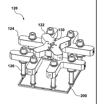
Referring now to Figs. 4 and 5, a manifold assembly for a 17" frame 200 for an
LCD is shown
generally at 120. The manifold assembly 120 is similar to manifold assembly
20, and includes an X-
shaped manifold 122, four V-shaped sub-manifolds 124, located on each of the
ends of manifold 122
and an injection nozzle assembly 126 depending from each arm of the sub-
manifolds 124. The X-
shaped manifold 122 distributes the melt from central sprue 130 along four
melt channels 128a to
4
CA 02726882 2013-08-09
H-7290-0-CA
interfaces 132, and then through melt channels 128b to injection nozzle
assemblies 126.
Referring now to Figs. 6 and 7, a manifold assembly for a 19" frame 300a for
an LCD is shown
generally at 220a. The manifold assembly 220a is similar to manifold assembly
20, and includes an X-
shaped manifold 222, four V-shaped sub-manifolds 224, located on each of the
ends of manifold 222
and an injection nozzle assembly 226 depending from each arm of the sub-
manifolds 224. The X-
shaped manifold 222 distributes the melt from central sprue 230 along four
melt channels 228a to
interfaces 232a, and then through melt channels 228b to injection nozzle
assemblies 226. The interface
232a between melt channels 228a and 228b is defined proximate the distal ends
of cross manifold
222a. The injection nozzle assembly 226 depends from each arm of the sub-
manifolds 224a proximate
the interface 232a.
Referring now to Figs. 8 and 9, an alternative manifold assembly for a 19"
frame 300b for an LCD is
shown generally at 220b. The manifold assembly 220b is similar to manifold
assembly 20, and
includes an X-shaped manifold 222 (the same manifold 222 as is used for
manifold assembly 300a),
four V-shaped sub-manifolds 224 (the same sub-manifolds 224 as used for
manifold assembly 300a),
located on each of the ends of manifold 222 and an injection nozzle assembly
226 depending from
each arm of the sub-manifolds 224. The X-shaped manifold 222 distributes the
melt from central
sprue 230 along four melt channels 228a to interfaces 232b, and then through
melt channels 228b to
injection nozzle assemblies 226. However, the arrangement of the sub-manifolds
224 relative to the
manifold 222 and the location of the interface 232 are different than with
manifold assembly 220a.
Each interface 232a is defined midway along each of the arms of cross manifold
222 rather than at the
distal ends. Additionally, the injection nozzle assemblies 226 depend from
each arm of the sub-
manifolds 224 proximate the distal ends of each arm of the sub-manifolds 224.
It will thus become apparent that while manifold assemblies 220a and 220b both
produce a 19" LCD
frame using substantially similar components, the distribution of the nozzle
assemblies 226 around the
frames differ, changing the locations of the gates (and thus, melt channel
length). Thus, manifold
assemblies 220a and 220b will produce LCD frames having different mechanical
properties.
Referring now to Figs. 10 and 11, a manifold assembly for a 21" frame 400 for
an LCD is shown
generally at 320. Manifold assembly 320 includes the same cross manifold 222,
and four of the same
sub-manifolds 224 as are used in manifold assemblies 220a and 220b. An
interface 332 is defined near
the distal end of each ann of cross manifold 222. To locate the nozzle
assemblies correctly over the
frame 400, the nozzle assemblies are located further along melt channel 228b
from interface 332.
Thus, by moving the location of the interface along the melt channel within
the manifold, and by
CA 02726882 2013-08-09
H-7290-0-CA
moving the location of the nozzle assemblies within the sub-manifolds, it is
possible to produce
molded articles having differing dimensions using substantially the same
components.
A method of manufacturing and assembly manifold assemblies in accordance with
an embodiment of
the invention will now be described. Manufacturing and assembly of manifold
assemblies 20, 120,
220a, 220b, and 300 etc. typically occur using a 'finish-to-order' (FTO)
process. That is to say,
manifolds 22, 122, 222, etc. are partially manufactured in batch quantities,
but left unfinished. During
the construction of manifolds 22, 122, 222, etc. melt channels 28a, 128a, 228a
are typically drilled
within the arms of the manifold towards their respective central sprue 30,
130, 230, etc. Optionally, a
distal end of melt channel 28a, 128a, 228a, is filled with a plug. Sub-
manifolds 24, 124, 224, etc. are
also manufactured, at least partially, in batch quantities, with melt channels
28b, 128b, 228b, being
drilled through to their intersecting point.
Upon receiving an order for a manifold assembly required to meet certain
specifications of a particular
mold design (requirements for flow length, placement of the mold gates, etc.),
a manifold assembly
(such as, but not limited to, manifold assemblies 20, 120, 220a, 220b, 320,
etc.) is assembled using
these partially-manufactured components. For commonly-used mold
specifications, a table can be
provided that lists preferred configurations. Fig. 12 shows a table listing
popular configurations for a
manifold assembly used to manufacture frames 100, 200, 300a, 300b, 400, etc.
Using a particular
frame size, and a particular number of injection nozzles, (i.e., number of
`drops'), one can select a
manifold assembly (20, 120, 220a, 220b, 320, etc.) having a desired melt
channel length (i.e., "flow
length").
Once the manifold assembly is selected, a manifold for that manifold assembly
is selected from a
predetermined set of manifolds 22, 122, 222, etc. Depending on the number of
drops required, a
plurality of sub-manifolds are also selected from a predetermined set of sub-
manifolds 24, 124, 224,
etc. Injection nozzles 26, 126, 226, etc. are also chosen, based upon
requirements determined by the
mold and the melt material.
After selecting the manifold and sub-manifolds, apertures are drilled into the
manifold 22, 122, 222,
etc. to intersect, in a perpendicular fashion, with melt channel 28a, 128a,
228a, etc, at a location on
each melt channel 28a, 128a, 22a, relative to the central sprue to define each
first portion of interface
32, 132, 232a, 232b, 332, etc.. An aperture is also drilled into each sub-
manifold 24, 124, 224, etc. to
intersect, in a perpendicular fashion the intersection point of melt channels
28b, 128b, 228b, etc. to
define a second portion of interface 32, 132, 232a, 232b, 332, etc.. An
additional hole is drilled into
the arm of each sub-manifold 24, 124, 224 in order to mount a injection
nozzles 26, 126, 226, etc. at a
6
CA 02726882 2013-08-09
H-7290-0-CA
predetermined location along each melt channel 28b.
After defining the complementary portions of the interfaces 32, 132, 232a,
232b, 332, etc., final
assembly of the desired manifold assembly 20, 120, 220a, 220b, 320, etc.
occurs. The sub-manifolds
are mounted to the manifold (in a fashion known to those of skill in the art),
so that their respective
portions of interface 32, 132, 232a, 232b, 332, etc. are mated together (with
the bushings inserted),
thereby providing fluid communication between melt channels 28a, 128a, 228a,
etc. and 28b, 128b,
228b, etc. Injection nozzles 26, 126, 226, etc. are mounted with the holes on
each arm of the sub-
manifolds (also in a fashion known to those of skill in the art) so that they
extend to the desired gate
locations for frames 100, 200, 300, etc.
The location of the apertures on the manifold 22, 122, 222, etc. combined with
the location of the
holes on the sub-manifolds 24, 124, 224, etc. (along with the injection
nozzles chosen), will determine
the total length of melt channels 28, which are sized so that injection
nozzles 26, 126, 226, etc. align
with the gates for the mold. Since the interface 32, 132, 232a, 232b, 332,
etc. can be located at any one
of many possible locations along the sub-manifolds 24, 124, 224, etc., and the
location of the injection
nozzles 26, 126, 226, etc. can also be located at any one of many possible
locations along each arm of
sub-manifold 24, 124, 224, etc., each combination of a particular manifold and
sub-manifolds (with the
correct mold) can produce a range of frame sizes and/or aspect ratios.
Additionally, by moving the
location of interface 32, 132, 232a, 232b, 332, etc., along the length of melt
channel 28a, 128a, 228a,
etc., the distribution of the gates around the frame can be adjusted.
It is contemplated by the inventors that in an alternate embodiment of the
invention, the manufacturer
could drill multiple holes into the manifold along the melt channel to better
accommodate different
sized molded articles. Unused holes would simply be fitted with plugs to
prevent melt leakage. It is
further contemplated by the inventors that in an alternate embodiment of the
invention, the sub-
manifolds 24, 124, 224, etc. are produced in batch quantities, but are in a
finished state. Manifold-
assemblies simply choose which sub-manifolds are to be mounted to the main
manifold.
Although the presently-illustrated embodiments of the invention are directed
towards manifold
assemblies used to produce frames for LCD displays, those of skill in the art
will recognize that the
manifold assemblies taught herein and means for production thereof can be
directed towards other
molded articles without departing from the scope of the invention.
7