Note: Descriptions are shown in the official language in which they were submitted.
CA 02726911 2015-08-17
SYSTEM FOR DECONTAMINATING WATER AND GENERATING WATER VAPOR
DESCRIPTION
BACKGROUND OF THE INVENTION
[Para 1] The present invention relates to a system for decontaminating
water and generating water vapor. More particularly, the present invention
relates to an improved method that utilizes a series of sensors and a control
system to vaporize water, remove dissolved solids and maximize recovery of
potable water from contaminated water via a horizontal water processing
vessel.
[Para 2] Desalinization (also desalination or desalinisation) refers to one
of
many processes for removing excess salt, minerals and other natural or
unnatural contaminants from water. Historically, desalinization converted sea
water into drinking water onboard ships. Modern desalinization processes are
still used on ships and submarines to ensure a constant drinking water supply
for the crew. But, desalinization is increasingly being used in arid regions
having scarce fresh water resources. In these regions, salt water from the
ocean is desalinated to fresh water suitable for consumption (i.e. potable) or
for
irrigation. The highly concentrated waste product from the desalinization
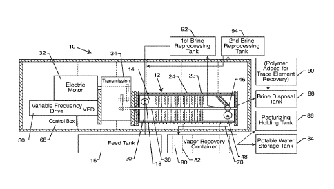
process is commonly referred to as brine, with salt (NaCI) being a typical
major
by-product. Most modern interest in desalinization focuses on developing
1
CA 02726911 2015-08-17
t =
cost-effective processes for providing fresh water for use in arid regions
where
fresh water availability is limited.
[Para 3] Large-scale desalinization is typically costly and generally
requires
large amounts of energy and an expensive infrastructure. For example, the
world's largest desalinization plant primarily uses multi-stage flash
distillation
and can produce 300 million cubic meters (m3) of water per year. The largest
desalinization plant in the United States desalinates 25 million gallons
(95,000
m3) of water per day. Worldwide, approximately 13,000 desalinization plants
produce more than 1 2 billion gallons (45 million m3) of water per day. Thus,
there is a constant need in the art for improving desalinization methods,
namely lowering costs and improving efficiency of the related systems.
[Para 4] Desalinization may be performed by many different processes.
For
example, several processes use simple evaporation-based desalinization
methods such as multiple-effect evaporation (MED or simply ME), vapor-
compression evaporation (VC) and evaporation-condensation. In general,
evaporation-condensation is a natural desalinization process performed by
nature during the hydrologic cycle. In the hydrologic cycle, water evaporates
into the atmosphere from sources such as lakes, oceans and streams.
Evaporated water then contacts cooler air and forms dew or rain. The resultant
water is generally free from impurities. The hydrologic process can be
replicated artificially using a series of evaporation-condensation processes.
In
basic operation, salt water is heated to evaporation. Salt and other
impurities
dissolve out from the water and are left behind during the evaporation stage.
2
CA 02726911 2015-08-17
The evaporated water is later condensed, collected and stored as fresh water.
Over the years, the evaporation-condensation system has been greatly
improved, especially with the advent of more efficient technology facilitating
the process. But, these systems still require significant energy input to
evaporate the water. An alternative evaporation-based desalinization method
includes multi-stage flash distillation, as briefly described above. Multi-
stage
flash distillation uses vacuum distillation. Vacuum distillation is a process
of
boiling water at less than atmospheric pressure by creating a vacuum within
the
evaporation chamber. Hence, vacuum distillation operates at a much lower
temperature than MED or VC and therefore requires less energy to evaporate
the water to separate the contaminants therefrom. This process is particularly
desirable in view of rising energy costs.
[Para 51 Alternative desalinization methods may include membrane-based
processes such as reverse osmosis (RO), electrodialisys reversal (EDR),
nanofiltration (NF), forward osmosis (FO) and membrane distillation (MD). Of
these desalinization processes, reverse osmosis is the most widely used.
Reverse osmosis uses semi-permeable membranes and pressure to separate
salt and other impurities from water. Reverse osmosis membranes are
considered selective. That is, the membrane is highly permeable to water
molecules while highly impermeable to salt and other contaminants dissolved
therein. The membranes themselves are stored in expensive and highly
pressurized containers. The containers arrange the membranes to maximize
surface area and salt water flow rate therethrough. Conventional-osmosis
3
CA 02726911 2015-08-17
desalinization systems typically use one of two techniques for developing high
pressure within the system: (1) high-pressure pumps; or (2) centrifuges. A
high-pressure pump helps filter salt water through the membrane. The
pressure in the system varies according to the pump settings and osmotic
pressure of the salt water. Osmotic pressure depends on the temperature of
the solution and the concentration of salt dissolved therein. Alternatively,
centrifuges are typically more efficient, but are more difficult to implement.
The centrifuge spins the solution at high rates to separate materials of
varying
densities within the solution. In combination with a membrane, suspended
salts and other contaminants are subject to constant radial acceleration along
the length of the membrane. One common problem with reverse osmosis in
general is the removal of suspended salt and clogging of the membrane over
time.
[Para 6]
Operating expenses of reverse osmosis water desalinization plants
are primarily determined by the energy costs required to drive the high-
pressure pump or centrifuge. A hydraulic energy recovery system may be
integrated into the reverse osmosis system to combat rising energy costs
associated with already energy intensive processes. This involves recovering
part of the input energy. For example, turbines are particularly capable of
recovering energy in systems that require high operating pressures and large
volumes of salt water. The turbine recovers energy during a hydraulic pressure
drop. Thus, energy is recovered in a reverse osmosis system based on pressure
differentials between opposite sides of the membrane. The pressure on the salt
4
CA 02726911 2015-08-17
water side is much higher than the pressure on the desalinated water side. The
pressure drop produces considerable hydraulic energy recoverable by the
turbine. Thus, the energy produced between high pressure and low pressure
sections of the reverse osmosis membrane is harnessed and not completely
wasted. Recovered energy may be used to drive any of the system components,
including the high-pressure pump or centrifuge. Turbines help reduce overall
energy expenditures to perform desalinization.
[Para 7] In general, reverse osmosis systems typically consume less energy
than thermal distillation and is, therefore, more cost effective. While
reverse
osmosis works well with somewhat brackish water solutions, reverse osmosis
may become overloaded and inefficient when used with heavily salted solutions,
such as ocean salt water. Other, less efficient desalinization methods may
include ionic exchange, freezing, geothermal desalinization, solar
humidification (HDH or MEH), methane hydrate crystallization, high-grade
water recycling or RE induced hyperthermia. Regardless of the process,
desalinization remains energy intensive. Future costs and economic feasibility
continue to depend on both the price of desalinization technology and the
costs of the energy needed to operate the system.
[Para 8] In another alternative method of desalinization, U.S. Patent No.
4,891,140 to Burke, Jr. discloses a method of separating and removing
dissolved minerals and organic material from water by destructive
distillation.
Here, water is heated to a vapor under controlled pressure. Dissolved salt
particles and other contaminants fall out of the solution as water evaporates.
CA 02726911 2015-08-17
,
1
An integrated hydrocyclone centrifuge speeds up the separation process. The
heated, high pressure clean water transfers energy back to the system through
heat exchange and a hydraulic motor. Net energy use is therefore relatively
lower than the aforementioned processes. In fact, net energy use is
essentially
equivalent to pump loss and heat loss from equipment operation. One
particular advantage of this design is that there are no membranes to replace.
This process removes chemicals and other matter that would otherwise damage
or destroy membrane-based desalinization devices.
[Para 9] Another patent, U.S. Patent No. 4,287,026 to Wallace,
discloses a
method and apparatus for removing salt and other minerals in the form of
dissolved solids from salt and other brackish waters to produce potable water.
Water is forced through several desalinization stages at high temperature and
at high centrifugal velocities. Preferably, the interior components spin the
water at speeds up to Mach 2 to efficiently separate and suspend dissolved
salt
and other dissolved solids from the vaporized water. The suspended salt and
other minerals are centrifugally forced outward to be discharged separately
from the water vapor. The separated and purified vapor or steam is then
condensed back to potable water. The system requires significantly less
operational energy than reverse osmosis and similar filtration systems to
efficiently and economically purify water. One drawback of this design is that
the rotating shaft is built into a vertical chamber. As a result, the rotating
shaft
sections are only solidly anchored to the base unit by a bearing and a bearing
cap. At high rotational speeds (e.g. over Mach 1), vibrations cause excessive
6
CA 02726911 2015-08-17
I
1
bearing shaft and seal failure. Another drawback is that a series of chambers
are bolted together in housing sections. The perforated plates are coupled to
these sections by an 0-ring seal. The housing and 0-ring seals tend to wear
over time due to salt penetration because the multiple chambers and housing
sections are connected via a plurality of nuts and bolts. In particular, the
assembly of the Wallace design is particularly laborious. Maintenance is
equally
labor intensive as it takes significant time to disassemble each of the
housing
sections, including the 0-rings, nuts and bolts. Of course, the device must be
reassembled after the requisite maintenance is performed. Each housing
section must be carefully put back together to ensure proper sealing
therebetween. The system is also prone to a variety of torque and maintenance
problems as the device ages, such as 0-ring leakage. Moreover, the rotating
shaft is connected to the power source by a gear drive, which contributes to
the
aforementioned reliability problems associated with the bearings, shafts and
seals. The system also fails to disclose a means for regulating the speed of
the
rotating shaft sections according to the osmotic pressure of the salt water
being desalinated. The static operation of the Wallace desalinization machine
is
therefore not as efficient as other modern desalinization devices.
[Para 1 0] Thus, there is a need in the art for an improved system that
includes sensors for monitoring real-time system information and controls for
adjusting the mechanical operation of the system to maximize decontamination
of the water, such as desalinization of the water, and minimize energy
consumption. Such a system should further incorporate multiple recycling
7
CA 02726911 2015-08-17
1 '
cycles to increase the recovery of potable water from approximately eighty
percent to between approximately ninety-six percent to ninety-nine percent,
should incorporate a polymer aided recovery system to extract trace elements
of residue compounds and should consume less energy than other
desalinization systems known in the art. The present invention fulfills these
needs and provides further related advantages.
SUMMARY OF THE INVENTION
[Para Ii] The present invention is directed to a system for
decontaminating
water, such as desalinating water, and generating water vapor, including
steam.
The system includes an elongated vessel defining an inner chamber. The vessel
is oriented generally horizontally. A water inlet is formed in the vessel for
introducing water therein. A plurality of trays is disposed within the inner
chamber in spaced relation to one another. The trays include scoops through
which water and water vapor pass. The scoops preferably include an inlet of a
first diameter and an outlet of a second smaller diameter. A plurality of
baffles,
typically apertured plates, are disposed between the trays. Each baffle has a
plurality of apertures through which water and water vapor passes. Preferably,
the apertures have an inlet of a first diameter and an outlet of a second
smaller
diameter. In one embodiment, at least one of the baffles includes a flow
director extending from a front face thereof and configured to direct flow of
the
water and water vapor towards a periphery of the baffle.
8
CA 02726911 2015-08-17
[Para 1 21 A rotatable shaft passes through the baffles, and is attached to
the
tray so as to rotate the trays within the inner chamber, while the baffles
remain
stationary. A drive rotates the shaft. Typically, a layer or sleeve of low
friction
material, or bearings, is disposed between the baffles and the shaft.
[Para 1 31 A contaminant outlet is formed in the vessel and typically in
fluid
communication with a contaminant water tank. A water vapor outlet is also
formed in the vessel and is in communication with a vapor recovery tank for
condensing the vapor to liquid water. In one embodiment, at least one treated
contaminated water tank is fluidly coupled to the vessel for reprocessing the
contaminated water by passing the treated contaminated water through the
system again.
[Para 14] In one embodiment, a controller is used to adjust the speed of
rotation of the shaft or the water input into the vessel. At least one sensor
is in
communication with the controller. At least one sensor is configured to
determine at least one of: 1) speed of rotation of the shaft or trays, 2)
pressure
of the inner chamber, 3) temperature of the water or water vapor, 4) water
input
rate, or 5) level of contaminated water to be processed.
[Para 1 5] In one embodiment, a turbine is connected to the water vapor
outlet of the vessel and operably connected to an electric generator. The
water
is heated to at least a boiling temperature thereof so as to create steam, and
the vapor and/or steam is passed through the turbine operably connected to
the electric generator. A treated water return may be disposed between the
turbine and the vessel water inlet.
9
CA 02726911 2015-08-17
[Para 1 6] In a particularly preferred embodiment, the system is attached
to a
portable framework, which may be transported via semi-trailer truck, ISO
container, or the like.
[Para 1 7] In use, the method for decontaminating water and generating the
water vapor comprises the steps of introducing a water having contaminants
into the vessel. The water is moved through the series of rotating trays
alternately separated by the stationary baffles so as to swirl and heat the
water
to effect the vaporization thereof to produce a vapor having at least some of
the contaminants separated therefrom. Typically, the water is heated to at
least
one hundred degrees Fahrenheit, but less than two hundred twelve degrees
Fahrenheit, if the system does not include a turbine and electric generator.
Preferably, the temperature of the vapor is raised to a pasteurization
temperature. This is done by rotating the trays to a speed where vapor
temperature reaches the pasteurization temperature.
[Para 1 8] The vapor is removed from the vessel for condensing apart from
the separated contaminants and remaining water. The water vapor is passed
through a recovery tank having spaced apart members in a flow path of the
vapor for condensing to liquid water.
[Para 19] In one embodiment, certain conditions are sensed, including at
least one of: 1) water input into the vessel, 2) the speed of rotation of the
trays,
3) pressure within the vessel, 4) temperature of the water or vapor, or 5)
level
of separated contaminants. The speed of rotation of the trays or water input
into the vessel may be adjusted in response to the sensed conditions. The
level
CA 02726911 2015-08-17
of separated contaminants and water in a holding tank or concentration of
contaminants in the treated water may also be sensed, and the separated
contaminants and water be reprocessed by recirculating them through the
vessel.
[Para 20] Other features and advantages of the present invention will
become
apparent from the following more detailed description, taken in conjunction
with the accompanying drawings, which illustrate, by way of example, the
principles of the invention.
BRIEF DESCRIPTION OF THE DRAWINGS
[Para 21] The accompanying drawings illustrate the invention. In such
drawings:
[Para 22] FIGURE 1 is a top schematic, and partially sectioned, view of a
system for decontaminating water and generating water vapor, in accordance
with the present invention;
[Para 23] FIGURE 2 is a side schematic, and partially sectioned, view of
the
system of FIG. 1;
[Para 24] FIGURE 3 is a top view illustrating the water processing vessel
having an upper portion thereof opened;
[Para 25] FIGURE 4 is an end view of the horizontal water processing vessel
attached to a portable framework, in accordance with the present invention;
[Para 26] FIGURE 5 is a top view of a rotating tray having a plurality of
scoops
therein;
11
CA 02726911 2015-08-17
[Para 27] FIGURE 6 is a cross-sectional view of a portion of the tray and a
scoop thereof;
[Para 28] FIGURE 7 is a top view of a baffle, used in accordance with the
present invention;
[Para 29] FIGURE 8 is a side view of a baffle having a water director
placed in
front thereof;
[Para 30] FIGURE 9 is a cross-sectional view of a portion of the baffle,
illustrating a tapered aperture thereof;
[Para 31] FIGURE 10 is a schematic illustrating the electric motor coupled
to
the transmission and then coupled to the shaft of the water processing vessel,
in accordance with the present invention;
[Para 32] FIGURE 11 is a schematic illustration of the system of the
present
invention, similar to FIG. 1, but illustrating the incorporation of a control
box
and various sensors, in accordance with the present invention;
[Para 33] FIGURE 12 is a top schematic view of the system of the present
invention, incorporating a turbine and electric generator;
[Para 34] FIGURE 13 is an end view of the water processing vessel,
illustrating a vapor outlet thereof; and
[Para 35] FIGURE 14 is a side schematic view of the system of FIG. 12.
DETAILED DESCRIPTION OF THE PREFERRED EMBODIMENTS
[Para 361 As shown in the drawings, for purposes of illustration, the
present
invention resides in a system and method for decontaminating water and
12
CA 02726911 2015-08-17
generating water vapor. The method and system of the present invention is
particularly suitable for desalinization of salt water, such as ocean or other
brackish waters, and this preferred treatment will be used for exemplary
purposes herein, although it will be understood by those skilled in the art
that
the system and method of the present invention could be used to
decontaminate other water sources. Moreover, as will be more fully described
herein, the system and method of the present invention can be used in
association with relatively clean water to create water vapor, in the form of
steam, which has a sufficient pressure and temperature so as to be passed
through a turbine which is operably connected to an electric generator for the
generation of electricity, or other steam heating applications.
[Para 37]
With reference now to FIGS. 1 and 2, the system, generally referred
to by the reference number 10, includes a water processing vessel or chamber
12 defining an inner chamber 14, wherein salt and other dissolved solids and
contaminants are removed from the water to produce essentially mineral-free,
potable water. In one embodiment, the processing vessel 12 receives
contaminated water from a feed tank 16 through an inlet valve 18 via a feed
tank tube 20. As described above, the source of water can be sea or ocean
water, other brackish waters, or even water which is contaminated with other
contaminants. Moreover, the present invention envisions supplying the
contaminated water directly from the source, wherein the feed tank 16 may not
necessarily be used.
13
CA 02726911 2015-08-17
[Para 381 With reference now to FIG. 3, in a particularly preferred
embodiment, the vessel 12 is comprised of a lower shell and an upper shell
portion 12b such that the lower and upper shell portions 12a and 12b can be
opened or removed relative to one another so as to access the contents within
the inner chamber 14 of the vessel 12. The water processing vessel 12
includes, within the inner chamber 14 a plurality of rotatable trays 22 spaced
apart from one another and having a baffle 24 disposed between the trays 22.
As will be more fully explained herein, the rotatable trays 22 include a
plurality
of scoops 26 formed therethrough and the baffles 24 typically comprise plates
having a plurality of apertures 28 formed therethrough. The baffles 24 are
fixed to the vessel 12 so as to be stationary. The baffles 24 may comprise a
lower portion disposed in the lower shell 12a of the vessel and an upper
portion attached to and disposed in the upper shell 12b of the vessel 12 and
designed to form a single baffle when the lower and upper shells 12a and 12b
of the vessel 12 are in engagement with one another and closed, or each baffle
24 can comprise a single piece which is attached to either the lower shell 12a
or the upper shell 12b and yet remain generally stationary as the water and
water vapor is passed therethrough.
[Para 39] A variable frequency drive 30 regulates the speed at which
electric
motor 32 drives a transmission 34 and a corresponding shaft 36. The shaft 36
is rotatably coupled to bearings or the like, typically Schmitt couplers or
ceramic bearings 38 and 40 at generally opposite ends of the vessel 12. The
shaft 36 extends through the trays 22 and baffles 24 such that only the trays
14
CA 02726911 2015-08-17
1
22 are rotated by the shaft. That is, the trays 22 are coupled to the shaft
36.
Bearings, or a low-friction material, such as a layer or sleeve of Teflon is
disposed between the rotating shaft 36 and the aperture plate baffle 24 to
reduce friction therebetween, yet stabilize and support the spinning shaft 36.
[Para 40] As can be seen from the drawings, the water processing vessel 12
is oriented generally horizontally. This is in contrast to the Wallace '026
device
wherein the water processing chamber was oriented generally vertically, and
the
top of the rotating shaft was secured by a bearing and a bearing cap, which
supported the chamber itself. As a result, the rotating shaft sections were
only
solidly anchored to the base of the unit. At high rotational operating speeds,
vibrations within the system cause excessive bearing, shaft and seal failure.
In
contrast, horizontally mounting the water processing vessel 12 to a frame
structure 42 distributes the rotational load along the length of the vessel 12
and reduces vibrations, such as harmonic vibrations, that could otherwise
cause
excessive bearing, shaft and seal failures. Moreover, mounting the vessel 12
to
the frame structure 42 enhances the portability of the system 10, as will be
more fully described herein. Supporting the very rapidly rotating shaft 36
through each baffle 24 further stabilizes the shaft and system and reduces
vibrations and damage caused thereby.
[Para 41] As mentioned above, the shaft 36, and trays 22 are rotated at a
very high speed, such as Mach 2. This moves the water through the scoops 26
of the trays 22, which swirls and heats the water such that a water vapor is
formed, and the contaminants, salts, and other dissolved solids are left
behind
CA 02726911 2015-08-17
1
,
and fall out of the water vapor. The water and water vapor is then passed
through the apertures 28 of the baffles 24 before being processed again
through the next rotating tray 22 with scoops 26. As the water and water vapor
passes through each subchamber of the vessel 1 2 , the temperature of the
water
vapor is increased such that additional water vapor is created and leaves the
salts, dissolved solids, and other contaminants behind in the remaining water.
The centrifugal forces on the water and contaminants force it to the wall of
the
inner chamber 14 and into a set of channels 44 which direct the contaminants
and non-vaporized water to an outlet 46. The water vapor which is generated
passes through a water vapor outlet 48 formed in the vessel 12. Thus, the
water vapor and the contaminants and remaining water are separated from one
another.
[Para 42] As mentioned above, the trays 22 are rotated by the shaft 36.
The
shaft 36 is supported within the interior of the water processing vessel 12 by
a
plurality of bearings, as mentioned above. The bearings are typically either
steel or made from ceramic materials. Prior art desalinization systems
incorporate standard roller bearings which would fail under high rotational
speeds and high temperatures. Thus, desalinization systems known in the
prior art had high failure rates associated with standard roller bearings. In
the
present invention, the sealed steel ball bearings or ceramic bearings 38 and
40
are more durable than standard roller bearings and fail less often under high
rotational speeds and temperatures. Moreover, the shaft 36 is intermittently
supported by the low friction materials, such as Teflon sleeves or bearings 50
16
CA 02726911 2015-08-17
disposed between the baffle plate 24 and the shaft 36. This further ensures
even distribution of weight and forces on the shaft 36 and improves the
operation and longevity of the system.
[Para 43] With particular reference now to FIGS. 5 and 6, an exemplary tray
22 is shown, having a plurality of scoops 26 formed therethrough. Although
fourteen scoops 26 are illustrated in FIG. 5, it will be appreciated that the
number may vary and can be several dozen in a single tray 22, thus the dotted
line represents multiple scoops of a variety of numbers.
[Para 44] FIG. 6 is a cross-sectional view of the tray 22 and the scoop 26
formed therein. In a particularly preferred embodiment, the scoops 26 are
tapered such that a diameter of an inlet 52 thereof is greater than the
diameter
of an outlet 54 thereof. The tapered scoop 26 is essentially a tube that has
the
vertical opening or inlet 52 substantially perpendicular to the horizontal
surface
of the rotating tray base 22. Water and vapor accelerates through the tapered
scoop 26 because the tapered scoop has a larger volume at the entrance 52
thereof and a smaller volume at the exit or outlet 54 thereof. The change in
volume from the inlet to the outlet of the tapered scoop 26 causes an increase
in velocity due to the Venturi effect. As a result, the water and water vapor
is
further agitated, increases in temperature and increases in velocity. This
further enables separation of the contaminants from within the water vapor.
The tapered scoop 26 may be attached to the rotating tray 22 by any means
known in the art.
17
CA 02726911 2015-08-17
[Para 45] Once again, it will be appreciated that there will be more or
less
tapered scoops 26 distributed in the entire area of the rotating tray 22, the
particular number and size of the scoops 26 will vary depending upon the
operating conditions of the system 10 of the present invention. Moreover, the
angle of the scoop 26, illustrated as approximately forty-five degrees in FIG.
6,
can be varied from tray to tray 22. That is, by increasing the angle of the
spinning scoop, such as by twenty-five degrees to thirty-one degrees to thirty-
six degrees on the subsequent tray, to forty degrees, forty-five degrees on a
next tray, etc. the increase in angle of the scoop 26 of the spinning tray 22
accommodates increases in pressure of the water vapor which builds up as the
water vapor passes through the vessel 12. The increase in angle can also be
used to further agitate and create water vapor, and increase the pressure of
the
water vapor, which may be used in a steam turbine, as will be more fully
described herein.
[Para 46] With reference now to FIGS. 7-9, a baffle 24, in the form of an
apertured plate, is shown in FIG. 7. In this case, the baffle 24 is formed as
a
first plate member 56 and a second plate member 58 which are connected by
connectors 60 to the inner wall of the vessel 12. The connectors 60 can
comprise bolts, rods, or any other connecting means which is adequate.
Alternatively, as described above, the baffle 24 can be formed as a single
unit
connected to either the upper or the lower vessel shell 12a and 12b. When
formed as dual plate members 56 and 58, preferably the plate members 56 and
18
CA 02726911 2015-08-17
58 inter-engage with one another when the vessel 12 is closed so as to form a
single baffle 24.
[Para 47] As described above, a plurality of apertures 28 are formed
through
the baffle plate 24. FIG. 9 is a cross-sectional view of one such aperture 28.
Similar to the tray described above, the aperture preferably includes an inlet
62
having a diameter which is greater than an outlet 64 thereof, such that the
aperture 28 is tapered which will increase the pressure and velocity of the
water
and water vapor which passes therethrough, further increasing the temperature
and creating additional vapor from the water. Similar to the tray 22 described
above, apertures 28 may be formed in the entire baffle plate, as represented
by
the series of dashed lines. The particular number and size of the apertures 28
may vary depending upon the operating conditions of the system 10.
[Para 48] With reference now to FIG. 8, the shaft 36 is illustrated
extending
through the baffle plate 24. In one embodiment, a cone-shaped water director
66 is positioned in front of the baffle 24. For example, the director 66 may
have a forty-five degree angle to deflect the remaining water and vapor from
the shaft 36 and towards the periphery or outer edge of the baffle plate 24
for
improved vaporization and higher percentage recovery of potable water.
[Para 49] Referring again to FIGS. 3 and 4, as mentioned above, in a
particularly preferred embodiment the vessel 12 is formed into two shells or
sections 12a and 12b. This enables rapid inspection and replacement of vessel
components, as necessary. Preferably, the wall of the inner chamber 14, and
any other components such as the trays 22, baffle plates 24, shaft 36, etc.
are
19
CA 02726911 2015-08-17
treated with Melonite, or other friction reducing and corrosion resistant
substance. Of course, these components can be comprised of materials which
are corrosion resistant and have a low friction coefficient, such as polished
stainless steel or the like. The lower and upper sections 1 2a and 12b of the
vessel 12 are preferably interconnected such that when closed they are
substantially air and water tight. Moreover, the closed vessel 12 needs to be
able to withstand high temperatures and pressures due to the water
vaporization therein during operation of the system 10.
[Para 501
With reference now to FIGS. 1, 2 and 10, typically a transmission 34
interconnects the electric motor 32 and the drive shaft 36. The speed of the
transmission 34 is set by the variable frequency drive 30. The variable
frequency drive 30 is primarily regulated by a computerized controller 68, as
will be more fully described herein. With particular reference to FIG. 10, the
shaft 70 of the motor is connected to an intermediate shaft 72 by a belt 74.
The intermediate shaft 72 is connected to the shaft by another belt 76. The
high-speed industrial belt and pulley system shown in FIG. 10 drives the shaft
36 inside the water processing vessel 12. As shown, a plurality of belts 74
and
76 and a set of intermediate shafts 72 increase the rotational output speed at
the shaft 36 by a multiple of the rotational input speed applied by the
electric
motor 32 on the electric motor driveshaft 70. Of course, the ratio of
rotational
input speed to rotational output speed can be changed by changing the relative
rotational velocities of the belts 74 and 76 and corresponding intermediate
shafts 72. By coupling the electric motor driveshaft 70 to the shaft 36 via
belts
CA 02726911 2015-08-17
74 and 76 and intermediate shaft 72, and adding a Schmitt coupler on the shaft
36 between the transmission 34 and the chamber 12, the present invention is
able to avoid the vibrational and reliability problems that plague other prior
art
desalinization systems.
[Para 51] With reference again to FIG. 1, as mentioned above, the water
vapor
is directed through a water vapor outlet 48 of the vessel 12. The water vapor
travels through a recovery tube 78 to a vapor recovery container or tank 80.
The water vapor then condenses and coalesces into liquid water within the
vapor recovery tank 80. To facilitate this, in one embodiment, a plurality of
spaced apart members 82, such as in the form of louvers, are positioned in the
flow pathway of the water vapor such that the water vapor can coalesce and
condense on the louvers and become liquid water. The liquid water is then
moved to a potable water storage tank 84 or a pasteurizing and holding tank
86. If the water and water vapor in the vessel 12 is heated to the necessary
temperature for pasteurization, so as to kill harmful microorganisms, zebra
mussel larvae, and other harmful organisms, the liquid water may be held in
holding tank 86.
[Para 52] In a particularly preferred embodiment, when the main goal of the
system 10 is to remove contaminants from the contaminated water, such as salt
water, so as to have potable water, the temperature of the water vapor is
heated
between one hundred degrees Fahrenheit and less than two hundred twelve
degrees Fahrenheit. Even more preferably, the water vapor is heated to
between one hundred forty degrees Fahrenheit and one hundred seventy
21
CA 02726911 2015-08-17
degrees Fahrenheit for pasteurization purposes. However, the water vapor
temperature is kept to a minimum, and preferably less than two hundred twelve
degrees Fahrenheit such that the water does not boil and become steam, which
is more difficult to condense and coalesce from water vapor to liquid water.
Instead, the water is boiled and the water vapor temperature above two
hundred twelve degrees Fahrenheit preferably only in instances where steam
generation is desirable for heating, electricity generating, etc. purposes as
will
be more fully described herein. This enables the present invention to both
pasteurize the water vapor and condense and coalesce the water vapor into
liquid water without complex refrigeration or condensing systems, which often
require additional electricity and energy.
[Para 53] In one embodiment, the contaminated water, referred to as brine
in
desalinization processes, is collected at outlet 46 and moved to a brine
disposal
tank 88. As shown in FIG. 1, polymers or other chemistry may be added to the
brine to recover trace elements, etc. Moreover, the salt from the brine may be
processed and used for various purposes, including generating table salt.
[Para 54] In one embodiment of the present invention, the treated
contaminated water is reprocessed by recycling the contaminants and
remaining water through the system 10 again. This may be done multiple
times such that the potable water extracted from the contaminated water
increases, such as up to ninety-nine percent. This may be done by directing
the contaminants and waste water from the outlet 46 to a first brine, or
contaminant, reprocessing tank 92. The remaining waste water, in the form of
22
CA 02726911 2015-08-17
. t
brine or other contaminants, is then reintroduced through inlet 18 of the
vessel
12 and reprocessed and recirculated through the vessel 12, as described above.
Additional potable water will be extracted in the form of water vapor for
condensing and collection in the vapor recovery tank 80. The remaining
contaminants and wastewater are then directed to a second brine or
contaminant reprocessing tank 94. The concentration of contaminants or brine
will be much higher in this reprocessing tank. Once a sufficient level of
wastewater or brine has been accumulated in the processing tank 94, this
contaminated water is then passed through the inlet 18 and circulated and
processed through the system 10, as described above. Extracted potable water
vapor is removed at outlet 48 and turned into liquid water in the vapor
recovery
tank 80, as described above. The resulting contaminants and wastewater can
then be placed into yet another reprocessing tank, or into the brine disposal
tank 88. It is anticipated that an initial pass-through of seawater will
yield, for
example, eighty percent to ninety percent potable water. The first
reprocessing
will yield an additional amount of potable water, such that the total
extracted
potable water is between ninety percent and ninety-five percent. Passing the
brine and remaining water through the system again can yield up to ninety-
nine percent recovery of potable water, by recycling the brine at little to no
increase in unit cost. Moreover, this reduces the volume of the brine or
contaminants, which can facilitate trace element recovery and/or reduce the
disposal costs thereof.
23
CA 02726911 2015-08-17
I
[Para 55] With reference now to FIG. 11, in a particularly preferred
embodiment, a computer system is integrated into the system 10 of the present
invention which regulates the variable frequency drive 30 based on
measurements taken from a plurality of sensors that continually read
temperature, pressure, flow rate, rotational rates of components and remaining
capacity of a variety of tanks connected to the water processing vessel 12.
Typically, these readings are taken in real-time.
[Para 56] For example, temperature and/or pressure sensors 96 may be
employed to measure the temperature of the water or water vapor within or
exiting the vessel 12, as well as the pressure thereof as needed. In response
to
these sensor readings, the control box 68 will cause the variable frequency
drive 30 to maintain the rotational speed of shaft 36, decrease the rotational
speed of the shaft 36, or increase the rotational speed of the shaft 36 to
either
maintain the temperature and pressure, reduce the temperature and pressure,
or increase the pressure and temperature, respectively, of the water and water
vapor. This may be done, for example, to ensure that the water vapor
temperature is at the necessary pasteurization temperature so as to kill all
harmful microorganisms and other organisms therein. Alternatively, or in
addition to, a sensor may be used to detect the rotational speed (RPMS) of the
shaft 36 and/or trays 22 to ensure that the system is operating correctly and
that the system is generating the necessary water vapor at a desired
temperature and/or pressure. The computerized controller may also adjust the
amount of water input through inlet 18 (GPMS) so that the proper amount of
24
CA 02726911 2015-08-17
water is input as to the amount of water vapor and wastewater which is
removed so that the system 10 operates efficiently. The control box 68 may
adjust the flow rate of water into the vessel 12, or even adjust the water
input.
[Para 571 For example, as indicated above, the contaminated water may
come from a feed tank 16, or can be from any other number of tanks, including
reprocessing tanks 92 and 94. It is also contemplated that the collected water
storage tank could be fluidly coupled to the inlet 18 so as to ensure that the
water is purified to a certain level or for other purposes, such as when
generating steam which requires a higher purity of water than the contaminated
water may provide. As such, one or more sensors 98 may track the data within
the tanks to determine water or wastewater/brine levels, concentrations, or
flow rates into the tanks or out of the tanks. The controller 68 may be used
to
switch the input and output of the tanks, such as when the brine is being
reprocessed from a first brine reprocessing tank 92 to the second brine
reprocessing tank 94, and eventually to the brine disposal tank 88, as
described above. Thus, when the first brine reprocessing tank reaches a
predetermined level, fluid flow from the feed tank 1 6 is shut off, and
instead
fluid is provided from the first brine reprocessing tank 92 into the vessel
12.
The treated contaminants and remaining wastewater are then directed into the
second brine reprocessing tank 94, until it reaches a predetermined level.
Then
the water is directed from the second brine reprocessing tank 94 through the
system and water processing vessel 1 2 to, for example, the brine disposal
tank
88. Brine water in the first reprocessing tank 92 may be approximately twenty
CA 02726911 2015-08-17
)
percent of the contaminated water, including most of the total dissolved
solids.
The residual brine which is finally directed to the brine disposal tank 88 may
only comprise one percent of the contaminated water initially introduced into
the decontamination system 10 via the feed tank 16. Thus, the temperature
and pressure sensors, RPM and flow meters can be used to control the desired
water output including water vapor temperature controls that result in
pasteurized water.
[Para 581 The controller 68 can be used to direct the variable frequency
drive
30 to power the motor 32 such that the shaft 36 is rotated at a sufficiently
high
velocity that the rotation of the trays boils the input water and creates
steam of
a desired temperature and pressure, as illustrated in FIG. 12. FIG. 12
illustrates
a steam turbine 100 integrated into the system 10. Water vapor in the form of
steam could be generated in the water processing vessel 12 to drive a high
pressure, low temperature steam turbine, which is coupled to an electric
generator 102, for cost- effective and economical generation of electricity.
[Para 591 For example, the water vapor can be heated to in excess of six
hundred degrees Fahrenheit and pressurized in excess of sixteen hundred
pounds per square inch (psi), which is adequate to drive the steam turbine
100.
Aside from the increased velocity of the trays, the incorporation of the
tapered
nature of the scoops 26 of the trays 22, and the tapered nature of the
apertures
28 of the aperture plate baffles 24 also facilitate the generation of water
vapor
and steam. Increasing the angles of the scoops 26, such as from twenty-five
degrees at a first tray to forty-five degrees at a last tray, also increases
water
26
CA 02726911 2015-08-17
,
,
vapor generation in the form of steam and increases the pressure thereof so as
to be able to drive the steam turbine 100. FIGS. 13 and 14 illustrate an
embodiment wherein a steam outlet 104 is formed at an end of the vessel 12
and the steam turbine 100 is directly connected thereto such that the
pressurized steam passes through the turbine 100 so as to rotate the blades
106 and shaft 108 thereof so as to generate electricity via the electric
generator
coupled thereto. A water vapor outlet 110 conveys the water vapor to a vapor
recovery container 80 or the like. The recovery tank 80 may need to include
additional piping, condensers, refrigeration, etc. so as to cool the steam or
high
temperature water vapor so as to condense it into liquid water.
[Para 60] Of course, it will be appreciated by those skilled in the art
that the
steam generated by the system 10 can be used for other purposes, such as
heating purposes, removal of oil from oil wells and tar and shale pits and the
like, etc.
[Para 61] It will also be appreciated that the present invention, by
means of
the sensors and controller 68 can generate water vapor of a lower temperature
and/or pressure for potable water production, which water vapor is directed
through outlet 48 directly into a vapor recovery container, and the system
sped
up to create high temperature water vapor or steam for passage through the
steam turbine 100 to generate electricity as needed. For example, during the
nighttime hours, the system 10 may be used to generate potable water when
very little electricity is needed. However, during the daylight hours, the
system
can be adjusted to generate steam and electricity.
27
CA 02726911 2015-08-17
[Para 62] As described above, many of the components of the present
invention, including the variable frequency drive 30, electric motor 32,
transmission 34, and water processing vessel 12 and the components therein
can be attached to a framework 42 which is portable. The entire system 10 of
the present invention can be designed to fit into a forty foot long ISO
container.
This container can be insulated with a refrigeration (HVAC) unit for
controlled
operating environment and shipping and storage. The various tanks, including
the feed tank, vapor recovery tank, portable water storage tank, and
contaminant/brine reprocessing or disposal tanks can either be fit into the
transportable container, or transported separately and connected to the inlet
and outlet ports as needed. Thus, the entire system 10 of the present
invention
can be easily transported in an ISO container, or the like, via ship, semi-
tractor
trailer, or the like. Thus, the system 10 of the present invention can be
taken
to where needed to address natural disasters, military operations, etc., even
at
remote locations. Such an arrangement results in a high level of mobility and
rapid deployment and startup of the system 10 of the present invention.
[Para 63] Although several embodiments have been described in detail for
purposes of illustration, the scope of the claims should not be limited to the
illustrative embodiments, but should be given the broadest interpretation
consistent with the description as a whole.
28