Note: Descriptions are shown in the official language in which they were submitted.
CA 02727366 2010-12-07
WO 2009/151497 PCT/US2009/001904
ANTI-SNORING DEVICE
BACKGROUND OF THE INVENTION
1. Field of the Invention.
[0001] The present invention relates to dental devices used for the
alleviation of
snoring. More particularly, the present invention relates to a device for
positioning a
person's lower jaw in a relatively forward position to thereby alleviate
snoring.
2. Description of the Related Art.
[0002] Snoring is a problem suffered by a large number of people. In many
cases,
snoring is caused by the relaxation of the tongue and the resulting blockage
of the
breathing airway. When the tongue of the sleeping individual relaxes and
creates such a
blockage and the individual subsequently forcibly passes air through the
breathing airway,
loud vibrations between the tongue and surrounding tissues will often result
in the noises
commonly referred to as snoring.
[0003] It is known that such snoring can be alleviated by displacing the
individual's lower jaw into a position that is relatively forward of its
normal position. A
variety of known devices are designed to forwardly displace an individual's
lower jaw
while they are sleeping to thereby alleviate snoring. While many such devices
would
appear to be effective for alleviating snoring, an improved device which can
be cost-
effectively manufactured and can be easily adjusted and used by the end-user
is desirable.
SUMMARY OF THE INVENTION
[0004] The present invention provides a user-friendly anti-snoring device that
can
be cost-effectively manufactured.
[0005] The invention comprises, in one form thereof, an anti-snoring device
for
mounting on the teeth of a user's upper and lower jaws. The device includes
first and
second arcuate members. The first member has a first side and an opposite
second side
wherein the first side defines a receptacle for receiving at least a portion
of the teeth of
either the user's upper or lower jaw and the second side of the first member
has a first
plurality of fasteners projecting outwardly therefrom. The first plurality of
fasteners are
formed by a plurality of elongate, parallel extending first projections that
define voids
between adjacent ones of the first projections. The first projections extend
in a direction
substantially transverse to a centerline of the device. The second member has
a first side
and an opposite second side wherein the first side defines a receptacle for
receiving at least
-1-
CA 02727366 2010-12-07
WO 2009/151497 PCT/US2009/001904
a portion of the teeth of the other of the user's upper or lower jaws, and the
second side has
a second plurality of fasteners projecting outwardly therefrom. The second
plurality of
fasteners are formed by a plurality of elongate, parallel extending second
projections that
define voids between adjacent ones of the first projections. The second
projections extend
in a direction substantially transverse to a centerline of the device. The
first and second
plurality of fasteners are selectively mutually engageable by disposing at
least one of the
first projections into a void defined between the second projections and
disposing at least
one of the second projections into a void defined between the first
projections whereby the
first and second members can be secured together in a plurality of
configurations defining
a plurality of relative positions between the user's upper and lower jaws when
the first and.
second members are mounted thereon.
[0006] The invention comprises, in another form thereof, an anti-snoring
device
for mounting on the teeth of a user's upper and lower jaws. The device
includes first and
second arcuate members. The first member has a first side and an opposite
second side
wherein the first side defines a receptacle for receiving at least a portion
of the teeth of
either the user's upper or lower jaw and the second side of the first member
has a first
plurality of fasteners projecting outwardly therefrom. The first plurality of
fasteners are
formed by a plurality of elongate, parallel extending first projections that
define voids
between adjacent ones of the first projections. Each of the first projections
has a neck
portion and a retaining head wherein the retaining head is disposed distal of
the neck
portion and has a width greater than the neck portion. The second member has a
first side
and an opposite second side wherein the first side defines a receptacle for
receiving at least
a portion of the teeth of the other of the user's upper or lower jaws, and the
second side has
a second plurality of fasteners projecting outwardly therefrom. The second
plurality of
fasteners are formed by a plurality of elongate, parallel extending second
projections that
define voids between adjacent ones of the first projections. Each of the
second projections
has a neck portion and a retaining head wherein the retaining head is disposed
distal of the
neck portion and has a width greater than the neck portion. The first and
second plurality
of fasteners are selectively mutually engageable by disposing at least one of
the first
projections into a void defined between the second projections and disposing
at least one
of the second projections into a void defined between the first projections
whereby the first
and second members can be secured together in a plurality of configurations
defining a
-2-
CA 02727366 2010-12-07
WO 2009/151497 PCT/US2009/001904
plurality of relative positions between the user's upper and lower jaws when
the first and
second members are mounted thereon.
[0007] The invention comprises, in yet another form thereof, an anti-snoring
device for mounting on the teeth of a user's upper and lower jaws. The device
includes
first and second arcuate members wherein each of the first and second arcuate
members
has a substantially common design. The first member has a substantially C-
shaped cross
section defining a receptacle for receiving at least a portion of the teeth of
either the user's
upper or lower jaw. The first member also has a first plurality of fasteners
disposed on the
C-shaped cross section opposite an opening of the receptacle and projecting
outwardly
from the first member. The first plurality of fasteners are formed by a
plurality of
elongate, parallel extending first projections that define voids between
adjacent ones of the
first projections. The first projections extend in a direction substantially
transverse to a
centerline of the device and each of the first projections has a neck portion
and a retaining
head wherein the retaining head is disposed distal of the neck portion and has
a width
greater than the neck portion. The second arcuate member has a substantially C-
shaped
cross section defining a receptacle for receiving at least a portion of the
teeth of the other
of the user's upper or lower jaws. The second member further includes a second
plurality
of fasteners disposed on the C-shaped cross section opposite an opening of the
receptacle
and projecting outwardly from the second member. The second plurality of
fasteners are
formed by a plurality of elongate, parallel extending second projections that
define voids
between adjacent ones of the second projections. The second projections extend
in a
direction substantially transverse to a centerline of the device and each of
the second
projections has a neck portion and a retaining head wherein the retaining head
is disposed
distal of the neck portion and has a width greater than the neck portion. The
first and
second plurality of fasteners are selectively mutually engageable by disposing
at least one
of the first projections into a void defined between the second projections
and disposing at
least one of the second projections into a void defined between the first
projections thereby
placing at least a portion of the retaining heads of the first and second
plurality of fasteners
into mutual engagement and securing the first arcuate member relative to the
second
arcuate member. The first and second members being selectively securable
together in a
plurality of configurations defining a plurality of relative positions between
the user's
upper and lower jaws when the first and second members are mounted thereon.
-3-
CA 02727366 2010-12-07
WO 2009/151497 PCT/US2009/001904
BRIEF DESCRIPTION OF THE DRAWINGS
[0008] The above mentioned and other features of this invention, and the
manner
of attaining them, will become more apparent and the invention itself will be
better
understood by reference to the following description of embodiments of the
invention
taken in conjunction with the accompanying drawings, wherein:
Figure 1 is a perspective view of an anti-snoring device in a first
configuration.
Figure 2 is a top view of the device in the first configuration.
Figure 3 is a side view of the device in the first configuration.
Figure 4 is a cross sectional view taken along line 4-4 of Figure 2.
Figure 5 is a perspective view of the device in a second configuration.
Figure 6 is a top view of the device in the second configuration.
Figure 7 is a side view of the device in the second configuration.
Figure 8 is a cross sectional view taken along line 8-8 of Figure 6.
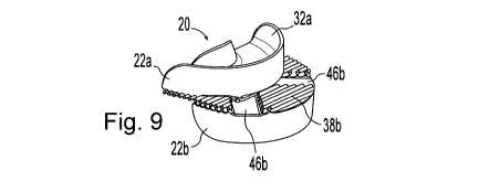
Figure 9 is a perspective view of the device in a third configuration.
Figure 10 is a top view of the device in the third configuration.
Figure 11 is a side view of the device in the third configuration.
Figure 12 is a cross sectional view taken along line 12-12 of Figure 10.
Figure 13 is a perspective view of a single arcuate member of the device.
Figure 14 is an end view of the arcuate member.
Figure 15 is a bottom view of the arcuate member.
Figure 16 is a cross sectional view taken along line 16-16 of Figure 15.
Figure 17 is a top view of the arcuate member.
Figure 18 is a schematic view showing the device in use.
Figure 19 is a schematic cross sectional view showing the device in use.
Figure 20 is a schematic top view showing an arcuate member mounted on
a user's lower jaw.
Figure 21 is a bottom view of another arcuate member.
Figure 22 is a schematic view illustrating different device configurations
utilizing the arcuate member of Figure 21.
Figure 23 is a detail view of the fasteners used to secure the arcuate
members together.
-4-
CA 02727366 2010-12-07
WO 2009/151497 PCT/US2009/001904
[0009] Corresponding reference characters indicate corresponding parts
throughout
the several views. Although the exemplification set out herein illustrates
embodiments of
the invention, in several forms, the embodiments disclosed below are not
intended to be
exhaustive or to be construed as limiting the scope of the invention to the.
precise forms
disclosed.
DETAILED DESCRIPTION OF THE INVENTION
[0010] One embodiment of an anti-snoring device 20 in accordance with the
present invention is depicted in Figure 1. Device 20 includes an upper
arcuately shaped
member 22a and a lower arcuately shaped member 22b. The arcuate, or horseshoe-
like,
shape of members 22a, 22b adapt members 22a, 22b for respective mounting on
the teeth
of a user's upper and lower jaws. Arcuate members 22a, 22b are injection
molded and
made of a,generally rigid plastic material.
[0011] In the embodiment illustrated in Figure 1, members 22a, 22b each have a
substantially common design and the use of the suffixes "a" and "b" is merely
used to
indicate that when in use, one of the members 22a, 22b will be mounted on the
user's
upper jaw while the other will be mounted on the user's lower jaw. As used
herein,
common reference numerals indicate common structures even though such
reference
numerals may employ different letter suffixes or no letter suffix at all.
[0012] While the embodiment illustrated in Figure 1 utilizes two arcuate
members
22a, 22b having a common design to form anti-snoring device 20, the present
invention
also encompasses anti-snoring devices which utilize two distinct designs for
the two
arcuate members. By utilizing two arcuate members which have a common design
as
exemplified in Figure 1, a number of efficiencies can be obtained. For
example, a single
mold, rather than two separate molds, can be used to manufacture the arcuate
members.
The necessity to coordinate the manufacture of an equal number of the two
different
designs is eliminated when both arcuate members have a common design.
Moreover, the
packaging of individual sets of two arcuate members to form an anti-snoring
device is
simplified when the members have a common design.
[0013] Not shown in Figures 1-12 is a moldable material 58 which is located in
receptacles 32a, 32b formed by arcuate members 22a, 22b. As discussed in
greater detail
below, moldable material 58 is used to fit members 22a, 22b to the intended
user's upper
and lower teeth respectively. This differential customization of members 22a,
22b,
-5-
CA 02727366 2010-12-07
WO 2009/151497 PCT/US2009/001904
however, is a post-manufacturing and distribution activity carried out by the
end user and
such fitted members 22a, 22b have a "common design" as this phrase is used
herein. This
fitting of the members 22a, 22b to the upper and lower teeth of the user may
also be done
under the guidance of a professional, however, such customization is so easy
to perform
that the assistance of a professional is unnecessary.
[0014] As can be seen in Figure 4, members 22a, 22b each have a substantially
C-
shaped cross section defined by a central portion 26a, 26b and a pair of
projecting limbs
28a, 28b. An opening 30a, 30b is defined between the distal ends of each of
the respective
pairs of limbs 28a, 28b and form receptacles 32a, 32b for receiving the users
teeth as will
be discussed in greater detail below. Openings 30a, 30b of receptacles 32a,
32b are
formed on a first side 34a, 34b of members 22a, 22b while the opposite second
side 36a,
36b of members 22a, 22b is defined a plurality of fasteners 38a, 38b.
[0015] The plurality of fasteners 38a, 38b are formed by a series of elongate,
parallel extending projections 40a, 40b. Projections 40a, 40b extend in a
parallel direction
generally transverse to centerline 51 (Fig. 20). Projections 40a, 40b have
enlarged head
portions 42a, 42b and define cooperating void spaces 44a, 44b between adjacent
projections 40a, 40b. Projections 40a, 40b are received in the corresponding
void spaces
44b, 44a of the other arcuate member to thereby secure the two arcuate members
22a, 22b
together in a selected configuration. Because there is a limited number of
parallel
projections 40a, 40b and corresponding voids 44a, 44b, the two pluralities of
fasteners 38a,
38b are securable together in a limited number of discrete configurations.
[0016] Projections 40 are shown in a detail view in Figure 23. (Figure 23
corresponds to a cross sectional view taken along centerline 51.) Projections
40 each
include a distal retaining head 42 defining a width 64 and a neck portion 63
defining a
width 66. The retaining head 42 of each projection 40 is located distal
relative to the neck
portion 63 and defines a greater width 64 than the width 66 of neck portion
63. Voids 44
defined between adjacent projections 40 have a shape that allows projections
40 from the
other arcuate member to be received therein with an enlarged portion defining
a width 70
which is adapted to receive head portion 42 and a narrower opening defining a
width 68
adapted to receive neck portion 63. In the illustrated embodiment, voids 44
have a shape
that closely mirrors projections 40. In alternative embodiments, the voids may
differ in
shape from the projections provided that the insertion of the projections of
one arcuate
-6-
CA 02727366 2010-12-07
WO 2009/151497 PCT/US2009/001904
member into the voids of the other arcuate member secures the two members
together. In
this regard, it is noted that the engagement of laterally extending surfaces
65 on the
underside of head portions 42 of the two arcuate members 22a, 22b secures the
two arcuate
members 22a, 22b together and inhibits their disassociation.
[0017] When securing the two arcuate members 22a, 22b together, at least one
of
the elongate projections 40 on each of the arcuate members 22a, 22b is
inserted into at
least one of the elongate, parallel extending voids 44 defined by adjacent
projections 40 on
the other of the arcuate members 22a, 22b. Projections 40 may be inserted into
voids 44
by pressing projections 40 downwardly into voids 44 such that retaining heads
42 pass
through the narrow opening having width 68. Since width 68 is smaller than the
width of
retaining head 42 in unstressed conditions, retaining heads 42 must be
compressed in a
width-wise direction, resulting in both a decrease in width 64 of retaining
heads 42 and an
increase in opening width 68, to allow for such insertion. Depending upon the
compressibility of the material used to form retaining heads 42. Although the
illustrated
embodiment utilizes solid retaining heads 42, in some alternative embodiments,
it may be
desirable to place passages 72 through some or all of the retaining heads 42
on one or both
of the members 22a, 22b for the full length of retaining heads 42 to thereby
increase the
compressibility of retaining heads 42 and facilitate the insertion and removal
of heads 42
from voids 44. Dashed outlines are used to indicate optional passages 72 on
several of the
retaining heads in Figure 23. It is also possible for arcuate members 22a, 22b
to be
secured together by aligning ends of projections 40 with voids 44 of the two
members 22a,
22b and sliding projections 40 into position within voids 44 to thereby avoid
the passage
of retaining heads 42 through width 68. Such sliding engagement, however,
would be
more cumbersome to accomplish.
[0018] Typically, the lower jaw only needs to be shifted about 3-6 millimeters
forward relative to its normal position and the range of discrete
configurations in which
members 22a, 22b can be secured advantageously provides for adjustment of
members
22a, 22b over a range that extends over at least about 6 mm. Figures 1-12
illustrate device
20 in three separate configurations. Figures 1-4 illustrate members 22a, 22b
secured
together with only a minimal forward displacement of the lower member 22b.
Figures 5-8
illustrate members 22a, 22b secured together with a moderate forward
displacement of the
lower member 22b. Figures 9-12 illustrate members 22a, 22b secured together
with a
-7-
CA 02727366 2010-12-07
WO 2009/151497 PCT/US2009/001904
large forward displacement of the lower member 22b. Individuals who snore
typically
prefer breathing through their mouth when sleeping and device 20 provides
airway
passages to facilitate the user's ability to breath through their mouth while
using device 20.
[0019] The illustrated arcuate members 22a, 22b each include substantially
unobstructed passageways 46a, 46b that define an airway passage between
members 22a,
22b when device 20 is in use. As most easily seen in Figures 3, 7 and 9, when
members
22a, 22b are secured together, passageways 46a, 46b are in communication and
together
form a common passageway 45. When in use, common passageway 48 provides a
breathing airway across the width of device 20, i.e., from a central interior
position 50
(Figure 20) relative to members 22a, 22b to an exterior position 52 (Figure
20) relative to
members 22a, 22b, to thereby facilitate the user's ability to breath through
their mouth.
Although the illustrated embodiment employs members 22a, 22b having a common
design
with each of the members 22a, 22b defining passageways 46a, 46b, alternative
embodiments which utilize arcuate members having different designs may employ
arcuate
members wherein only one of the arcuate members defines a substantially
unobstructed
passageway for facilitating the user's ability to breath through their mouth.
In still other
embodiments of the present invention, neither of the arcuate members may have
a
substantially unobstructed passageway for forming a breathing airway. In such
embodiments where neither arcuate member includes an unobstructed passageway,
the two
members forming the anti-snoring device may have a substantially common
design, or,
may utilize two distinct designs.
[0020] In the embodiment depicted in Figures 1-18, each member 22a, 22b
defines
two substantially unobstructed passageways 46a, 46b which are arranged in a
substantially
V-shaped orientation. The V-shaped orientation of passageways 46 is most
easily seen in
Figure 15. (A single arcuate member 22 which may be used to form either an
upper or
lower member is shown in Figures 13-17 and, thus, the reference numerals do
not include
suffixes.) As can also be seen in Figure 15, side 36 of central portion 26
which is disposed
opposite opening 30 of receptacles 32 defines a surface area 37 which is
substantially
entirely defined by the plurality of fasteners 38 and passageways 46. As also
shown in
Figure 15, passageways 46 extend from an interior arcuate perimeter 54 of
member 22 to
an exterior arcuate perimeter 56 with the plurality of fasteners 38 positioned
adjacent both
edges 49 of passageways 46 for the full length of passagways 46. While the
plurality of
-8-
CA 02727366 2010-12-07
WO 2009/151497 PCT/US2009/001904
fasteners 38 extend along a majority of exterior perimeter 56, interior
arcuate perimeter 54
has a smaller variable radius and openings 47 which passageways 46 form on
interior
arcuate perimeter 54 extend for a majority of interior arcuate perimeter 54.
In embodiment
illustrated in Figure 15, passageways 46 have a width 45 which is sufficiently
large that
openings 47 extend not only for a majority of interior perimeter 54 but for
substantially the
entire interior perimeter 54. Passageways 46 may utilize various widths 45
including
widths smaller than those employed with the illustrated embodiments.
Advantageously,
such passageway widths 45 are at least about 1 millimeter or greater.
[0021] As shown in Figure 19, a moldable material 58 can be disposed in
receptacles 32 such that the receptacles are moldably conformable to the
user's teeth 60.
Moldable material 58 is not shown in the other figures for purposes of
graphical clarity.
Moldable material 58 is a thermoplastic material capable of being molded when
heated to
a temperature of greater than about 1152 F. To fit members 22a, 22b to the end
user's teeth
60, the end user, after purchasing a device 20, will place members 22a, 22b in
water that
has been heated to a temperature greater than 1152 F. After members 22a, 22b,
and the
moldable material 58 in receptacles 32a, 32b, has been heated to a temperature
greater than
1152 F, the end user will remove members 22a, 22b from the heated water and
place
members 22a, 22b over the end user's teeth thereby causing moldable material
58 within
receptacles 32a, 32b to be shaped or fitted to the user's teeth 60 on which
the respective
members will be mounted when device 20 is in use. Moldable material 58 may
also be a
chemical-set material, which would not require heating and cooling but,
rather, time to set.
The use of such moldable material 58 to fit a dental appliance to an end
user's teeth is well
known in the art.
[0022] As can be seen in Figure 20, members 22 are mounted on the anterior
teeth
of the end user but do not extend to cover all of the user's posterior teeth
62. Alternative
embodiments of the present invention, however, could employ larger arcuate
members 22
that did extend to engage and cover all of the user's teeth.
[0023] A second embodiment of an arcuate member in accordance with the present
invention is illustrated in Figures 21 and 22. This second embodiment utilizes
arcuate
members 23 having a common design and which are similar to arcuate members 22
except
for the arrangement of substantially unobstructed passageway 24 on members 23.
Instead
of having two passageways arranged in a V-shaped pattern, arcuate members 23
have a
-9-
CA 02727366 2010-12-07
WO 2009/151497 PCT/US2009/001904
single unobstructed passageway 24 that extends along the centerline of member
23 and has
a width 25. Width 25 is sufficiently large that the opening of passageway 24
on the
interior arcuate perimeter of member 23 extends over a majority of the
interior arcuate
perimeter of member 23. Unlike member 22, however, the opening of passageway
24 does
not extend over the substantial entirety of the interior arcuate perimeter.
[0024] Members 23 may be secured together in a plurality of discrete positions
in
the same manner as arcuate members 22 and Figure 22 schematically depicts a
lower
member 23a and the position of its passageway 24a and two alternative
positions 23b and
23c of the upper member in dashed outlines and the positions of their
respective
passageways 24b, 24c. Dashed outline 23b depicts a configuration wherein the
lower
member 23a is displaced forwardly by only a minimal distance. Dashed outline
23c
depicts a configuration wherein lower member 23a has been displaced forwardly
by a large
distance. As depicted in Figure 22, by providing a passageway 24 that extends
parallel
with the direction of displacement, the width of the common passageway formed
by the
individual passageways 24 of the upper and lower members 23 remains at width
25 of the
individual passageways 24 for the full range of displacement. In the
embodiment of
Figures 1-18 wherein members 22 have passageways 46 forming a V-shaped
pattern, the
overlap between the upper and lower passageways 46a, 46b becomes progressively
smaller
as the forward displacement of the lower member 22b is increased. This
diminution of the
common passageway does not occur for the embodiment of Figures 21 and 22 and,
thus,
the embodiment of Figures 21 and 22 can be beneficial for those individuals
who need to
utilize a large forward displacement of the lower jaw.
[0025] While this invention has been described as having an exemplary design,
the
present invention may be further modified within the spirit and scope of this
disclosure.
This application is therefore intended to cover any variations, uses, or
adaptations of the
invention using its general principles.
-10-