Note: Descriptions are shown in the official language in which they were submitted.
CA 02727376 2014-05-28
74769-3240
1
INTERFERENCE MITIGATION BY TRANSMITTING
ON A SECOND, LOWER, POWER LEVEL
[0001] The present application claims priority to provisional U.S.
Application Serial
No. 61/076,366, entitled "FLEXIBLE MULTICARRIER COMMUNICATION SYSTEM,"
filed June 27, 2008, assigned to the assignee hereof.
BACKGROUND
I. Field
[0002] The present disclosure relates generally to communication, and
more
specifically to techniques for communicating in a wireless communication
network.
II. Background
[0003] Wireless communication networks are widely deployed to provide
various
communication content such as voice, video, packet data, messaging, broadcast,
etc. These
wireless networks may be multiple-access networks capable of supporting
multiple users by
sharing the available network resources. Examples of such multiple-access
networks include
Code Division Multiple Access (CDMA) networks, Time Division Multiple Access
(TDMA)
networks, Frequency Division Multiple Access (FDMA) networks, Orthogonal FDMA
(OFDMA) networks, and Single-Carrier FDMA (SC-FDMA) networks.
[0004] A wireless communication network may include a number of base
stations that
can support communication for a number of user equipments (UEs). A UE may
communicate
with a base station via the downlink and uplink. The downlink (or forward
link) refers to the
communication link from the base station to the UE, and the uplink (or reverse
link) refers to
the communication link from the UE to the base station.
[0005] A base station may transmit data and control information on the
downlink to a
UE and/or may receive data and control information on the uplink from the UE.
On the
downlink, a transmission from the base station may observe interference due to
transmissions
from neighbor base stations. On the uplink, a transmission from the UE may
observe
interference due to transmissions from other UEs communicating with the
CA 02727376 2010-12-07
WO 2009/158546
PCT/US2009/048725
2
neighbor base stations. The interference may degrade performance on both the
downlink and uplink.
SUMMARY
[0006]
Techniques for communicating on multiple carriers in a wireless
communication network are described herein. A carrier may be a range of
frequencies
that may be used for communication and may be defined by a particular center
frequency and a particular bandwidth. A carrier may be separated from an
adjacent
carrier by a guard band and may also have other attributes, as described
below. The
multiple carriers may be used to support communication in dominant
interference
scenarios, which are scenarios in which high interference may be observed from
interfering base stations and/or interfering UEs.
[0007] In an
aspect, different transmit power levels may be used for different
carriers to mitigate interference and achieve good overall performance. In one
design, a
first base station may be assigned one or more carriers among multiple
carriers available
for communication. A second base station may be assigned one or more carriers
not
assigned to the first base station. The first base station may communicate on
each
assigned carrier at a first (e.g., full) transmit power level. The first base
station may
communicate on each unassigned carrier at a second transmit power level, which
may
be lower than the first transmit power level in order to reduce interference
to the second
base station. The first and second base stations may belong in different power
classes.
For example, the first base station may be a high-power base station whereas
the second
base station may be a lower-power base station, or vice versa. The first and
second base
stations may also support different association/access types. For example, the
first base
station may support unrestricted access whereas the second base station may
support
restricted access, or vice versa. Communication on the multiple carriers may
be
supported as described below.
[0008] In
another aspect, control information may be sent on a designated carrier to
support communication on at least one other carrier. A station (e.g., a base
station or a
UE) may communicate on the at least one carrier. The station may exchange
(e.g., send
or receive) control information on the designated carrier for the
communication on the
at least one carrier. The control information may comprise scheduling grants
or
CA 02727376 2013-07-12
,
74769-3240
3
assignments, channel quality indicator (CQI) information, acknowledgement
(ACK)
information, etc. The control information may be sent with a higher transmit
power level on
the designated carrier, which may improve reliability.
[0009] In yet another aspect, auto-configuration may be performed
to select a suitable
carrier for communication. A station (e.g., a base station or a UE) may
determine a metric for
each of multiple carriers available for communication. The metric may comprise
at least one
parameter other than signal strength, e.g., received signal quality, pathloss,
etc. The station
may select a carrier for communication from among the multiple carriers based
on the metric
for each carrier. The station may then communicate on the selected carrier. In
one design,
both data and control information may be exchanged (e.g., sent or received)
via the selected
carrier. In another design, control information may be exchanged via the
selected carrier, and
data may be exchanged via the selected carrier and/or another carrier.
100101 In yet another aspect, a base station may broadcast bar
information indicating
the status of carriers. The base station may determine bar information for
each carrier. In one
design, the bar information for each carrier may indicate whether that the
carrier is barred
from use. In another design, the bar information for a given carrier may
indicate that the
carrier is not barred for a first set of UEs and is barred for a second set of
UEs. The bar
information for each carrier may also comprise other information that may be
used to control
access and communication on the carrier. The base station may broadcast the
bar information
to UEs, which may use the bar information to determine access to the base
station.
[0010a] According to one aspect of the present invention, there is
provided a method of
communicating in a wireless communication network, comprising: communicating
on a first
carrier at a first transmit power level by a first base station; and
communicating on a second
carrier at a second transmit power level by the first base station, the second
transmit power
level being lower than the first transmit power level to reduce interference
to a second base
station communicating on the second carrier, the first and second base
stations belonging in
different power classes or supporting different association types, wherein the
first and second
carriers are for downlink, wherein communicating on the first carrier
comprises sending
control information on the first carrier at the first transmit power level to
a first user
CA 02727376 2013-07-12
74769-3240
3a
equipment (UE) and a second UE and sending a first data transmission on the
first carrier at
the first transmit power level to the first UE, and wherein the communicating
on the second
carrier comprises sending a second data transmission on the second carrier at
the second
transmit power level to the second UE.
[0010b] According to another aspect of the present invention, there is
provided an
apparatus for wireless communication, comprising: means for communicating on a
first
carrier at a first transmit power level by a first base station; and means for
communicating on
a second carrier at a second transmit power level by the first base station,
the second transmit
power level being lower than the first transmit power level to reduce
interference to a second
base station communicating on the second carrier, the first and second base
stations belonging
in different power classes or supporting different association types, wherein
the first and
second carriers are for downlink, wherein the means for communicating on the
first carrier
comprises means for sending control information on the first carrier at the
first transmit power
level to a first user equipment (UE) and a second UE and means for sending a
first data
transmission on the first carrier at the first transmit power level to the
first UE, and wherein
the means for communicating on the second carrier comprises means for sending
a second
data transmission on the second carrier at the second transmit power level to
the second UE.
10010c] According to still another aspect of the present invention,
there is provided an
apparatus for wireless communication, comprising: at least one processor
configured to
communicate on a first carrier at a first transmit power level by a first base
station, and to
communicate on a second carrier at a second transmit power level by the first
base station, the
second transmit power level being lower than the first transmit power level to
reduce
interference to a second base station communicating on the second carrier, the
first and second
base stations belonging in different power classes or supporting different
association types,
wherein the first and second carriers are for downlink, wherein the at least
one processor
configured to communicate on the first carrier comprises the at least one
processor configured
to send control information on the first carrier at the first transmit power
level to a first user
equipment (UE) and a second UE and the at least one processor configured to
send a first data
transmission on the first carrier at the first transmit power level to the
first UE, and wherein
CA 02727376 2013-07-12
74769-3240
3b
the at least one processor configured to communicate on the second carrier
comprises the at
least one processor configured to send a second data transmission on the
second carrier at the
second transmit power level to the second UE.
[0010d] According to yet another aspect of the present invention, there
is provided a
computer program product, comprising: a non-transitory computer-readable
medium
comprising: code for causing at least one computer to communicate on a first
carrier at a first
transmit power level by a first base station, and code for causing the at
least one computer to
communicate on a second carrier at a second transmit power level by the first
base station, the
second transmit power level being lower than the first transmit power level to
reduce
interference to a second base station communicating on the second carrier, the
first and second
base stations belonging in different power classes or supporting different
association types,
wherein the first and second carriers are for downlink, wherein the code for
causing the at
least one computer to communicate on the first carrier comprises code for
causing the at least
one computer to send control information on the first carrier at the first
transmit power level
to a first user equipment (UE) and a second UE and code for causing the at
least one computer
to send a first data transmission on the first carrier at the first transmit
power level to the first
UE, and wherein the code for causing the at least one computer to communicate
on the second
carrier comprises code for causing the at least one computer to send a second
data
transmission on the second carrier at the second transmit power level to the
second UE.
[0010e] According to a further aspect of the present invention, there is
provided a
method of communicating in a wireless communication network, comprising:
determining a
carrier having less interference from a first base station among multiple
carriers available for
communication; and communicating on the carrier by a second base station, the
first and
second base stations belonging in different power classes or supporting
different association
types, wherein the first base station communicates control information on a
first carrier of the
multiple carriers available for communication to a first user equipment (UE)
and a second UE,
and wherein the second base station communicates a data transmission on a
second carrier of
the multiple carriers available for communication to the second UE
CA 02727376 2013-07-12
74769-3240
3c
[0010f] According to yet a further aspect of the present invention,
there is provided an
apparatus for wireless communication, comprising: means for determining a
carrier having
less interference from a first base station among multiple carriers available
for
communication; and means for communicating on the carrier by a second base
station, the
first and second base stations belonging in different power classes or
supporting different
association types, wherein the first base station communicates control
information on a first
carrier of the multiple carriers available for communication to a first user
equipment (UE) and
a second UE, and wherein the second base station communicates a data
transmission on a
second carrier of the multiple carriers available for communication to the
second UE.
[0010g] According to still a further aspect of the present invention, there
is provided a
method of communicating in a wireless communication network, comprising:
detecting a first
base station operating on a first carrier at a first transmit power level and
on a second carrier
at a second transmit power level, the second transmit power level being lower
than the first
transmit power level to reduce interference to a second base station operating
on the second
carrier, the first and second base stations belonging in different power
classes or supporting
different association types; and communicating with the first base station on
the first carrier at
the first transmit power level, or the second carrier at the second transmit
power level, or both,
wherein communicating with the first base station on the first carrier
comprises
communicating control information or a first data transmission or both control
information
and a first data transmission on the first carrier at the first transmit power
level, and wherein
communicating on the second carrier comprises communicating a second data
transmission on
the second carrier at the second transmit power level.
[0010h] According to another aspect of the present invention, there is
provided an
apparatus for wireless communication, comprising: means for detecting a first
base station
operating on a first carrier at a first transmit power level and on a second
carrier at a second
transmit power level, the second transmit power level being lower than the
first transmit
power level to reduce interference to a second base station operating on the
second carrier, the
first and second base stations belonging in different power classes or
supporting different
association types; and means for communicating with the first base station on
the first carrier
CA 02727376 2013-07-12
74769-3240
3d
at the first transmit power level, or the second carrier at the second
transmit power level, or
both, wherein the means for communicating with the first base station on the
first carrier
comprises communicating control information or a first data transmission or
both control
information and a first data transmission on the first carrier at the first
transmit power level,
and wherein communicating on the second carrier comprises communicating with
the first
base station a second data transmission on the second carrier at the second
transmit power
level.
[0010i] According to yet another aspect of the present invention,
there is provided a
method of communicating in a wireless communication network, comprising:
communicating
on at least one carrier; and exchanging control information on a first carrier
for the
communication on the at least one carrier, the first carrier being different
from the at least one
carrier, wherein the at least one carrier and the first carrier are for
downlink, wherein the
communicating on the at least one carrier comprises sending at least one data
transmission to
at least one user equipment (UE) on the at least one carrier, and wherein the
exchanging
control information on the first carrier comprises sending control information
to the at least
one UE on the first carrier for the at least one data transmission on the at
least one carrier.
[0010j1 According to yet another aspect of the present invention,
there is provided an
apparatus for wireless communication, comprising: means for communicating on
at least one
carrier; and means for exchanging control information on a first carrier for
the communication
on the at least one carrier, the first carrier being different from the at
least one carrier, wherein
the at least one carrier and the first carrier are for downlink, wherein the
means for
communicating on the at least one carrier comprises means for sending at least
one data
transmission to at least one user equipment (UE) on the at least one carrier,
and wherein the
means for exchanging control information on the first carrier comprises means
for sending
control information to the at least one UE on the first carrier for the at
least one data
transmission on the at least one carrier.
[00111 Various aspects and features of the disclosure are described
in further detail
below.
CA 02727376 2013-07-12
74769-3240
3e
BRIEF DESCRIPTION OF THE DRAWINGS
[0012] FIG. 1 shows a wireless communication network.
[0013] FIG. 2 shows a carrier structure for a single carrier.
[0014] FIGS. 3A and 3B show carrier structures for multiple carriers.
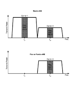
100151 FIG. 4 shows operation on two carriers by a macro base station and
operation
on one of two carriers by a pico or femto base station.
100161 FIG. 5 shows communication on multiple downlink and uplink
carriers.
CA 02727376 2010-12-07
WO 2009/158546
PCT/US2009/048725
4
[0017] FIGS. 6 and 7 show a process and an apparatus, respectively, for
communication on multiple carriers by a base station.
[0018] FIGS. 8 and 9 show a process and an apparatus, respectively, for
communication on an assigned carrier by a base station.
[0019] FIGS. 10 and 11 show a process and an apparatus, respectively, for
communication by a UE.
[0020] FIGS. 12 and 13 show a process and an apparatus, respectively, for
communication on multiple carriers with control information sent on a single
carrier.
[0021] FIGS. 14 and 15 show a process and an apparatus, respectively, for
communication on a carrier selected with auto-configuration.
[0022] FIGS. 16 and 17 show a process and an apparatus, respectively, for
broadcasting bar information by a base station.
[0023] FIG. 18 shows a block diagram of a base station and a UE.
DETAILED DESCRIPTION
[0024] The techniques described herein may be used for various wireless
communication networks such as CDMA, TDMA, FDMA, OFDMA, SC-FDMA and
other networks. The terms "network" and "system" are often used
interchangeably. A
CDMA network may implement a radio technology such as Universal Terrestrial
Radio
Access (UTRA), cdma2000, etc. UTRA includes Wideband CDMA (WCDMA) and
other variants of CDMA. cdma2000 covers IS-2000, IS-95 and IS-856 standards. A
TDMA network may implement a radio technology such as Global System for Mobile
Communications (GSM). An OFDMA network may implement a radio technology
such as Evolved UTRA (E-UTRA), Ultra Mobile Broadband (UMB), IEEE 802.11 (Wi-
Fi), IEEE 802.16 (WiMAX), IEEE 802.20, Flash-OFDMC), etc. UTRA and E-UTRA
are part of Universal Mobile Telecommunication System (UMTS). 3GPP Long Term
Evolution (LTE) and LTE-Advanced (LTE-A) are new releases of UMTS that use E-
UTRA. UTRA, E-UTRA, UMTS, LTE, LTE-A and GSM are described in documents
from an organization named "3rd Generation Partnership Project" (3GPP).
cdma2000
and UMB are described in documents from an organization named "3rd Generation
Partnership Project 2" (3GPP2). The techniques described herein may be used
for the
wireless networks and radio technologies mentioned above as well as other
wireless
CA 02727376 2010-12-07
WO 2009/158546
PCT/US2009/048725
networks and radio technologies. For clarity, certain aspects of the
techniques are
described below for LTE, and LTE terminology is used in much of the
description
below.
[0025] FIG. 1
shows a wireless communication network 100, which may be an LTE
network or some other network. Wireless network 100 may include a number of
evolved Node Bs (eNBs) 110 and other network entities. An eNB may be a station
that
communicates with the UEs and may also be referred to as a base station, a
Node B, an
access point, etc. Each eNB 110 may provide communication coverage for a
particular
geographic area. In 3GPP, the term "cell" can refer to a coverage area of an
eNB and/or
an eNB subsystem serving this coverage area, depending on the context in which
the
term is used.
[0026] An eNB
may provide communication coverage for a macro cell, a pico cell,
a femto cell, and/or other types of cell. A macro cell may cover a relatively
large
geographic area (e.g., several kilometers in radius) and may allow
unrestricted access by
UEs with service subscription. A pico cell may cover a relatively small
geographic area
and may allow unrestricted access by UEs with service subscription. A femto
cell may
cover a relatively small geographic area (e.g., a home) and may allow
restricted access
by UEs having association with the femto cell (e.g., UEs in a Closed
Subscriber Group
(CSG), UEs for users in the home, etc.). An eNB for a macro cell may be
referred to as
a macro eNB. An eNB for a pico cell may be referred to as a pico eNB. An eNB
for a
femto cell may be referred to as a femto eNB or a home eNB. In the example
shown in
FIG. 1, eNBs 110a, 110b and 110c may be macro eNBs for macro cells 102a, 102b
and
102c, respectively. eNB 110x may be a pico eNB for a pico cell 102x. eNBs 110y
and
110z may be femto eNBs or home eNBs for femto cells 102y and 102z,
respectively.
An eNB may support one or multiple (e.g., three) cells.
[0027] Wireless
network 100 may also include relay stations, e.g., a relay station
110r. A relay station is a station that receives a transmission of data and/or
other
information from an upstream station (e.g., an eNB or a UE) and sends a
transmission of
the data and/or other information to a downstream station (e.g., a UE or an
eNB). A
relay station may also be a UE that relays transmissions for other UEs. A
relay station
may also be referred to as a relay eNB, a relay, etc.
[0028] Wireless
network 100 may be a homogeneous network that includes eNBs of
one type, e.g., only macro eNBs, or only femto eNBs. Wireless network 100 may
also
CA 02727376 2010-12-07
WO 2009/158546
PCT/US2009/048725
6
be a heterogeneous network that includes eNBs of different types, e.g., macro
eNBs,
pico eNBs, femto eNBs, relays, etc. The different types of eNBs may have
different
transmit power levels, different coverage areas, and different impact on
interference in
wireless network 100. For example, macro eNBs may have a high transmit power
level
(e.g., 20 Watts) whereas pico eNBs, femto eNBs, and relays may have a lower
transmit
power level (e.g., 1 Watt). The techniques described herein may be used for
both
homogeneous and heterogeneous networks. The techniques may be used for
different
types of eNBs and relays.
[0029] Wireless
network 100 may support synchronous or asynchronous operation.
For synchronous operation, the eNBs may have similar frame timing, and
transmissions
from different eNBs may be approximately aligned in time. For asynchronous
operation, the eNBs may have different frame timing, and transmissions from
different
eNBs may not be aligned in time. The techniques described herein may be used
for
both synchronous and asynchronous operation.
[0030] A
network controller 130 may couple to a set of eNBs and may provide
coordination and control for these eNBs. Network controller 130 may
communicate
with eNBs 110 via a backhaul. eNBs 110 may also communicate with one another,
e.g.,
via wireless or wireline backhaul.
[0031] UEs 120
may be dispersed throughout wireless network 100, and each UE
may be stationary or mobile. A UE may also be referred to as a terminal, a
mobile
station, a subscriber unit, a station, etc. A UE may be a cellular phone, a
personal
digital assistant (PDA), a wireless modem, a wireless communication device, a
handheld device, a laptop computer, a cordless phone, a wireless local loop
(WLL)
station, etc. A UE may be able to communicate with macro eNBs, pico eNBs,
femto
eNBs, relays, etc. In FIG. 1, a solid line with double arrows indicates
desired
transmissions between a UE and a serving eNB, which is an eNB designated to
serve
the UE on the downlink and/or uplink. A dashed line with double arrows
indicates
interfering transmissions between a UE and an eNB.
[0032] Wireless
network 100 may support operation on a configurable system
bandwidth. For example, wireless network 100 may be an LTE network that
supports
operation on system bandwidth of 1.25, 2.5, 5, 10 or 20 megahertz (MHz). The
system
bandwidth may be partitioned into subbands. For example, a subband may cover
1.08
CA 02727376 2010-12-07
WO 2009/158546
PCT/US2009/048725
7
MHz, and there may be 1, 2, 4, 8 or 16 subbands for system bandwidth of 1.25,
2.5, 5,
or 20 MHz, respectively.
[0033] FIG. 2
shows a design of a carrier structure 200 supporting communication
on a single downlink carrier. The downlink carrier may have a bandwidth of BW
and
may be centered at a frequency off,. An eNB may transmit a primary
synchronization
signal (PSS) and a secondary synchronization signal (SSS) for each cell in the
eNB.
The synchronization signals may be used by UEs for cell detection and
acquisition. The
eNB may also transmit various control channels such as a Physical Broadcast
Channel
(PBCH), a Physical Control Format Indicator Channel (PCFICH), a Physical HARQ
Indicator Channel (PHICH) and a Physical Downlink Control Channel (PDCCH) in
LTE. The PBCH may carry certain system information. The PCFICH may convey the
number of symbol periods (M) used for the control channels in a subframe. The
PHICH
may carry ACK information to support hybrid automatic retransmission (HARQ).
The
PDCCH may carry control information such as scheduling grants for UEs for data
transmission on the downlink and uplink. The eNB may also transmit one or more
data
channels such as a Physical Downlink Shared Channel (PDSCH) in LTE. The PDSCH
may carry data for UEs scheduled for data transmission on the downlink. The
eNB may
transmit the PSS, SSS and PBCH in the center 1.08 MHz of the downlink carrier.
The
eNB may transmit the PCFICH, PHICH, PDCCH and PDSCH across all or part of the
downlink carrier in each symbol period in which these channels are sent.
[0034] A UE may
be within the coverage of multiple eNBs. One of these eNBs
may be selected to serve the UE. The serving eNB may be selected based on
various
criteria such as received signal quality, pathloss, etc. Received signal
quality may be
given by a signal-to-noise ratio (SNR), a carrier-to-interference ratio (C/I),
etc.
[0035] A UE may
operate in a dominant interference scenario, which is a scenario
in which the UE may observe high interference from one or more interfering
eNBs. A
dominant interference scenario may occur due to restricted association. For
example, in
FIG. 1, UE 120y may be close to femto eNB 110y and may have high received
power
for eNB 110y. However, UE 120y may not be able to access femto eNB 110y due to
restricted association and may then connect to macro eNB 110c with lower
received
power (as shown in FIG. 1) or to femto eNB 110z also with lower received power
(not
shown in FIG. 1). UE 120y may then observe high interference from femto eNB
110y
on the downlink and may also cause high interference to eNB 110y on the
uplink.
CA 02727376 2010-12-07
WO 2009/158546
PCT/US2009/048725
8
[0036] A
dominant interference scenario may also occur due to range extension,
which is a scenario in which a UE connects to an eNB with lower pathloss and
lower
SNR among all eNBs detected by the UE. For example, in FIG. 1, UE 120x may
detect
macro eNB 110b and pico eNB 110x and may have lower received power for eNB
110x
than eNB 110b. Nevertheless, it may be desirable for UE 120x to connect to
pico eNB
110x if the pathloss for eNB 110x is lower than the pathloss for macro eNB
110b. This
may result in less interference to the wireless network for a given data rate
for UE 120x.
Range extension may also be used for relays.
[0037] In an
aspect, communication in dominant interference scenarios may be
supported by using multiple carriers and assigning eNBs to different carriers
such that
good performance can be achieved. In general, any number of carriers may be
used for
each of the downlink and uplink. The number of carriers may be dependent on
various
factors such as the system bandwidth, the desired or required bandwidth for
each
carrier, etc. The available carriers may be assigned to the eNBs in various
manners, as
described below.
[0038] FIG. 3A
shows a design of a carrier structure 300 supporting communication
on two downlink carriers 1 and 2. The system bandwidth of BW may be
partitioned
into two carriers, and each downlink carrier may have a bandwidth of BW /2 .
For
example, a 10 MHz system bandwidth may be partitioned into two 5 MHz carriers.
In
general, the system bandwidth may be partitioned equally or unequally, and the
downlink carriers may have the same or different bandwidths.
[0039] In one
design, the two downlink carriers may be assigned to eNBs of
different power classes. High-power eNBs (e.g., macro eNBs) may be assigned
one
downlink carrier (e.g., carrier 1), and lower-power eNBs (e.g., pico and femto
eNBs)
may be assigned the other downlink carrier (e.g., carrier 2). In another
design, the two
downlink carriers may be assigned to eNBs of different association/access
types.
Unrestricted eNBs (e.g., macro and pico eNBs) may be assigned one downlink
carrier
(e.g., carrier 1), and restricted eNBs (e.g., femto eNBs) may be assigned the
other
downlink carrier (e.g., carrier 2). The two carriers may also be assigned to
eNBs in
other manners.
[0040] FIG. 3B
shows a design of a carrier structure 310 supporting communication
on M downlink carriers 1 through M, where M may be greater than two. The
system
bandwidth of BW may be partitioned into M equal parts, and each downlink
carrier may
CA 02727376 2010-12-07
WO 2009/158546
PCT/US2009/048725
9
have a bandwidth of BW / M . For example, a 10 MHz system bandwidth may be
partitioned into four 2.5 MHz carriers. In general, the system bandwidth may
be
partitioned equally or unequally into M parts. The M downlink carriers may
have the
same or different bandwidths. For example, a 10 MHz system bandwidth may be
partitioned into (i) four 2.5 MHz carriers, (ii) one 5 MHz carrier and two 2.5
MHz
carriers, (iii) eight 1.25 MHz carriers, (iv) one 5 MHz carrier, one 2.5 MHz
carrier, and
two 1.25 MHz carriers, or (v) some other combination of carriers.
[0041] The M
downlink carriers may be assigned to eNBs in various manners. In
one design, eNBs of different power classes may be assigned different downlink
carriers. In another design, eNBs of different association types may be
assigned
different downlink carriers. In yet another design, eNBs causing high
interference to
one another may be assigned different downlink carriers. For example, the 10
MHz
system bandwidth may be partitioned into one 5 MHz carrier and two 2.5 MHz
carriers.
In the example shown in FIG. 1, macro eNB 110c may be assigned the 5 MHz
carrier,
femto eNB 110y may be assigned one 2.5 MHz carrier, and femto eNB 110z may be
assigned the other 2.5 MHz carrier.
[0042] In
general, an eNB may be assigned one or more downlink carriers. In one
design, the eNB may transmit at full power on each assigned downlink carrier.
In one
design, the eNB may avoid transmitting on each unassigned downlink carrier or
may
transmit at a lower power level in order to reduce interference to other eNBs
assigned
this carrier. The eNB may thus transmit at different power levels on the
assigned and
unassigned downlink carriers. In general, higher transmit power may be used
for an
assigned carrier, and lower (or no) transmit power may be used for an
unassigned
carrier. For each eNB, an assigned carrier may have less interference from
other eNBs
than an unassigned carrier.
[0043] FIG. 4
shows exemplary operation by a macro eNB on two downlink
carriers 1 and 2. The horizontal axis may represent frequency, and the
vertical axis may
represent transmit power. The macro eNB may be assigned downlink carrier 1 and
may
transmit at full power on this carrier. The macro eNB may transmit at a lower
power
level on downlink carrier 2 (as shown in FIG. 4) or may avoid transmitting on
carrier 2
(not shown in FIG. 4) in order to reduce interference to other eNBs assigned
carrier 2.
[0044] FIG. 4
also shows exemplary operation by a pico or femto eNB for the
example in which two downlink carriers 1 and 2 are available. The pico or
femto eNB
CA 02727376 2010-12-07
WO 2009/158546
PCT/US2009/048725
may be assigned downlink carrier 2 and may transmit at full power on this
carrier. The
pico or femto eNB may avoid transmitting on downlink carrier 1 (as shown in
FIG. 4)
or may transmit at a lower power level on carrier 1 (not shown in FIG. 4) in
order to
reduce interference to the macro eNB assigned carrier 1.
[0045] The
design shown in FIG. 4 may support communication in a restricted
association scenario, with a femto eNB being assigned downlink carrier 2. A UE
that is
within the range of the femto eNB may connect to the macro eNB on downlink
carrier 1
and can avoid high interference from the femto eNB on downlink carrier 2. The
design
shown in FIG. 4 may also support communication in a range extension scenario,
with a
pico eNB being assigned downlink carrier 2. A UE that is within the range of
the pico
eNB may connect to the pico eNB on downlink carrier 2 and can avoid high
interference from the macro eNB on downlink carrier 1.
[0046] In one
design, the available downlink carriers may be assigned to eNBs in a
dynamic and flexible manner. The available downlink carriers may be assigned
to
eNBs based on one or more metrics, which may relate to network performance, UE
performance, etc.
[0047] In one
design, downlink carriers may be assigned to eNBs based on a
predetermined schedule. The schedule may indicate the number of downlink
carriers to
assigned to different eNBs and when the assigned downlink carriers are valid.
The
schedule may be generated by a network operator to obtain good performance.
For
example, four downlink carriers may be available, three downlink carriers may
be
assigned to macro eNBs during the day, and three downlink carriers may be
assigned to
femto eNBs at night when more people are at home and expected to use their
femto
eNBs.
[0048] In
another design, eNBs may communicate with one another to assign
downlink carriers among these eNBs. For example, a macro eNB (or a network
entity)
may obtain the loading of neighbor eNBs and may assign downlink carriers to
itself and
the neighbor eNBs such that good performance can be achieved.
[0049] In one
design, one downlink carrier may be designated as a downlink anchor
carrier for an eNB. The downlink anchor carrier may have one or more of the
following
attributes:
= Can be transmitted at full power by the eNB,
CA 02727376 2010-12-07
WO 2009/158546
PCT/US2009/048725
11
= Has low interference from other eNBs,
= Carry synchronization signals used for acquisition,
= Carry control information for data transmission on the anchor carrier
and/or
other carriers,
= Support communication for UEs capable of operating on a single carrier,
and
= May be a preferred downlink carrier for operation.
[0050] In one
design, one uplink carrier may be designated as an uplink anchor
carrier for the eNB. The uplink anchor carrier may have one or more of the
following
attributes:
= Has low interference from other UEs served by other eNBs,
= Carry control information for data transmission on the anchor carrier
and/or
other carriers,
= Support communication for UEs capable of operating on a single carrier,
and
= May be a preferred uplink carrier for operation.
[0051] In one
design, the downlink anchor carrier and/or the uplink anchor carrier
may be specific for the eNB and may be applicable for all UEs served by the
eNB. In
another design, the downlink anchor carrier and/or the uplink anchor carrier
may be
specific for a UE, and different UEs may have different downlink anchor
carriers and/or
different uplink anchor carriers.
[0052] In one
design, unrestricted eNBs may transmit synchronization signals (e.g.,
the PSS and SSS) on each of the available downlink carriers. Restricted eNBs
may
transmit synchronization signals on each assigned downlink carrier. Macro eNBs
may
use lower power when transmitting synchronization signals on unassigned
downlink
carriers. UEs may detect for eNBs based on the synchronization signals
transmitted by
these eNBs. The UEs may be able to detect the synchronization signals from
both
macro eNBs and restricted eNBs on the downlink carriers assigned to the
restricted
eNBs since the macro eNBs transmit at a lower power level on these carriers.
The UEs
may also determine received signal quality, pathloss, and/or other metrics
based on the
synchronization signals. Serving eNBs may be selected for the UEs based on the
metric(s).
[0053] An eNB
may have one or more assigned downlink carriers and one or more
unassigned downlink carriers. The eNB may serve one or more UEs on each
assigned
CA 02727376 2010-12-07
WO 2009/158546
PCT/US2009/048725
12
downlink carrier and may also serve zero or more UEs on each unassigned
downlink
carrier. For example, the eNB may serve strong UEs (e.g., UEs with lower
pathloss) on
the unassigned downlink carriers since these UE may be able to overcome high
interference from other eNBs. The eNB may serve weak UEs (e.g., UEs with
higher
pathloss) on the assigned downlink carriers so that these UE can observe less
interference from other eNBs.
[0054] The eNB
may transmit data and control information on the assigned and
unassigned downlink carriers in various manners. The control information may
comprise scheduling grants, ACK information, etc. In one design, the eNB may
transmit data and control information for each UE on the same downlink
carrier. This
design may simplify operation since data and control information are sent on
the same
carrier. In another design, the eNB may transmit data and control information
for a
given UE on different downlink carriers. For example, the eNB may transmit
control
information on an assigned downlink carrier and may transmit data on an
unassigned
downlink carrier to the UE. This design may improve performance since the eNB
can
transmit the control information at higher power on the assigned downlink
carrier. In
one design, a new PDCCH format may be used to convey scheduling grants for
data
transmission on multiple downlink carriers. The scheduling grants for
different
downlink carriers may be sent in different payload and/or with different
scrambling on
the PDCCH. The PHICH may carry ACK information for data transmission on
multiple
uplink carriers.
[0055] In one
design, frequency reservation may be used to improve performance
and may also be referred to as intra-carrier bandwidth partitioning. An eNB
may be
assigned a downlink carrier and may reserve a portion of the assigned downlink
carrier
for another eNB. For example, the eNB may be assigned a 5 MHz carrier with
four
subbands. The eNB may reserve one or more subbands in the assigned downlink
carrier
for another eNB. The eNB may transmit the PSS, SSS, PBCH and a cell-specific
reference signal for each cell on the assigned downlink carrier in the normal
manner.
The eNB may also transmit control information and data on the portion of the
assigned
downlink carrier that is not reserved for another eNB. The eNB may avoid
transmitting,
or may transmit at a lower power level, on the reserved portion of the
assigned
downlink carrier.
CA 02727376 2010-12-07
WO 2009/158546
PCT/US2009/048725
13
[0056]
Frequency reservation may be used to dynamically re-allocate frequency
resources among eNBs. Frequency reservation may be used when and as needed.
For
example, the number of subbands to reserve for another eNB may be dependent on
the
amount of data to send by the other eNB. The subbands may also be reserved for
as
long as needed by the other eNB. Frequency reservation may also be used to
assign
frequency resources with granularity smaller than one carrier.
[0057] An eNB
may broadcast bar information indicating the status of different
downlink carriers. In one design, the bar information for a downlink carrier
may
indicate whether that carrier is available for use by UEs. For example, the
bar
information for each assigned downlink carrier may indicate that the carrier
is available
for use, and the bar information for each unassigned downlink carrier may
indicate that
the carrier is unavailable for use. A UE detecting a downlink carrier being
barred by the
eNB may (i) search for another downlink carrier that is not barred by the eNB
or (ii)
select another eNB on that downlink carrier.
[0058] In
another design, the bar information for a downlink carrier may identify
UEs allowed to access the carrier and/or UEs not allowed to access the
carrier. For
example, the bar information for an unassigned downlink carrier may bar a
first set of
UEs from accessing the carrier and may allow a second set of UEs to access the
carrier.
The first set of UEs may be unable to reliably communicate with the eNB on the
unassigned downlink carrier at lower transmit power level and may then (i)
search for
another downlink carrier assigned to the eNB or (ii) select another eNB
assigned this
downlink carrier. The second set of UEs may be able to reliably communicate
with the
eNB on the unassigned downlink carrier even at the lower transmit power level.
[0059] The
various designs and features described above for downlink carriers may
also be used for uplink carriers. In general, any number of uplink carriers
may be
available for the uplink. The number of uplink carriers may be dependent on
various
factors such as the system bandwidth, the desired or required bandwidth for
each uplink
carrier, etc. The available uplink carriers may be assigned to eNBs, e.g., as
described
above for the downlink carriers. Higher (e.g., full) transmit power may be
used for each
assigned uplink carrier, and lower (or zero) transmit power may be used for
each
unassigned uplink carrier.
[0060] A given
eNB may serve one or more UEs on each assigned uplink carrier
and may also serve zero or more UEs on each unassigned uplink carrier. In one
design,
CA 02727376 2010-12-07
WO 2009/158546
PCT/US2009/048725
14
a UE may transmit data and control information on the same carrier to the eNB.
This
design may simplify operation. In another design, a UE may transmit data on an
assigned or unassigned uplink carrier and may transmit control information on
an
assigned uplink carrier to the eNB. This design may improve reliability for
the control
information, which may observe less interference on the assigned uplink
carrier from
other UEs communicating with other eNBs.
[0061] In one
design, frequency reservation may be used to reserve a portion of an
uplink carrier assigned to an eNB for use by another eNB. Frequency
reservation may
be used when and as needed and may be triggered by signaling exchanged via the
backhaul, as described above.
[0062] FIG. 5
shows a design of communication by an eNB. In the example shown
in FIG. 5, three downlink carriers Dl, D2 and D3 are available on the
downlink, and
three uplink carriers Ul, U2 and U3 are available for the uplink. The eNB may
be
assigned downlink carriers D2 and D3 as well as uplink carriers U2 and U3.
[0063] In one
design, the eNB may have a downlink anchor carrier and an uplink
anchor carrier. The downlink anchor carrier may be one of the assigned
downlink
carriers, e.g., downlink carrier D2. The uplink anchor carrier may be one of
the
assigned uplink carriers, e.g., uplink carrier U2. The downlink anchor carrier
may carry
downlink control information from the eNB to support data transmission on the
downlink and uplink on all carriers. The uplink anchor carrier may carry
uplink control
information from the UEs to support data transmission on the downlink and
uplink on
all carriers. For example, the downlink control information may include
downlink
grants for data transmission on the downlink, uplink grants for data
transmission on the
uplink, ACK information for data transmission on the uplink, etc. The uplink
control
information may include resource requests for data transmission on the uplink,
CQI
information for data transmission on the downlink, ACK information for data
transmission on the downlink, etc. The eNB may transmit data to the UEs on the
downlink anchor carrier as well as other downlink carriers, e.g., subject to
the lower
transmit power limitation for the unassigned downlink carrier. The UEs may
transmit
data to the eNB on the uplink anchor carrier as well as other uplink carriers,
e.g., subject
to the lower transmit power limitation for unassigned uplink carrier.
CA 02727376 2010-12-07
WO 2009/158546
PCT/US2009/048725
[0064] In
another aspect, a station may perform auto-configuration to select a
suitable carrier for communication from among multiple carriers. The station
may be a
UE or a network entity, which may be a base station, a network controller,
etc.
[0065] In one
design, the station may determine a metric for each carrier available
for communication. The metric may comprise received signal quality, pathloss,
signal
strength, and/or other parameters. The metric may also comprise a transmit
energy
metric, an effective geometry metric, a projected data rate metric, a utility
metric, or
some other metric computed based on the at least one parameter.
[0066] The
station may select a carrier for communication from among the multiple
carriers based on the metric for each carrier. In one design, the metric may
comprise
received signal quality, and the station may select the carrier with the
highest received
signal quality for communication. In another design, the metric may comprise
pathloss,
and the station may select the carrier with the lowest pathloss for
communication. In
yet another design, the metric may comprise loading, and the station may
select the
carrier with the least loading for communication. In yet another design, the
metric may
comprise access quality determined based on quality-of-service (QoS) and/or
data rate,
and the station may select the carrier with the highest access quality for
communication.
The station may also select a carrier for communication in other manners.
[0067] The
metric for each carrier may be determined based on information that
may be obtained in different manners, e.g., depending on whether the station
is a UE or
a network entity. In one design, the metric for each carrier may be determined
based on
over-the-air measurements, which may be used to determine received signal
quality,
pathloss, etc. In another design, the metric for each carrier may be
determined based on
reports sent by UEs to a network entity. In yet another design, the metric for
each
carrier may be determined based on backhaul information received by the
network
entity from at least one base station.
[0068] Anchor
carriers may be used to facilitate communication, as described
above. Anchor carriers may also be used to mitigate self-desensitization. If a
wireless
network uses a number of carriers on the downlink and uplink, then self-
desensitization
at a UE may occur, and downlink carriers closest to uplink transmission may
suffer
from interference due to limited isolation between a transmit port and a
receive port of a
duplexer at the UE. To mitigate self-desensitization, uplink and downlink
control may
CA 02727376 2010-12-07
WO 2009/158546
PCT/US2009/048725
16
be sent on carriers that may be farthest from each other. The uplink and
downlink
transmissions may be from different radio technologies.
[0069] FIG. 6
shows a design of a process 600 for communication by a first base
station in a wireless network. The first base station may communicate on a
first carrier
at a first (e.g., full) transmit power level (block 612). The first base
station may
communicate on a second carrier at a second transmit power level, which may be
lower
than the first transmit power level to reduce interference to a second base
station
communicating on the second carrier (block 614). The first carrier may have
less
interference from the second base station than the second carrier.
[0070] The
first and second base stations may belong in different power classes or
may support different association/access types. In one design, the first base
station may
belong in a high power class whereas the second base station may belong in a
lower
power class, or vice versa. In another design, the first base station may
support
unrestricted access whereas the second base station may support restricted
access, or
vice versa.
[0071] In one
design, the first and second carriers may be for the downlink. For
block 612, the first base station may send a first data transmission on the
first carrier at
the first transmit power level to a first UE. For block 614, the first base
station may
send a second data transmission on the second carrier at the second transmit
power level
to a second UE. In one design, the first base station may send control
information to the
first and second UEs on the first carrier, which may be a downlink anchor
carrier. In
another design, the first base station may send control information to the
first UE on the
first carrier and may send control information to the second UE on the second
carrier.
The first base station may also send at least one synchronization signal on
each of the
first and second carriers to allow UEs to detect the first base station.
[0072] In
another design, the first and second carriers may be for the uplink. For
block 612, the first base station may receive a first data transmission sent
by a first UE
on the first carrier at the first transmit power level. For block 614, the
first base station
may receive a second data transmission sent by a second UE on the second
carrier at the
second transmit power level. In one design, the first base station may receive
control
information from the first and second UEs on the first carrier, which may be
an uplink
anchor carrier. In another design, the first base station may receive control
information
CA 02727376 2010-12-07
WO 2009/158546
PCT/US2009/048725
17
from the first UE on the first carrier and may receive control information
from the
second UE on the second carrier.
[0073] In one
design, the first and second carriers may be assigned to the first and
second base stations based on a static or semi-static schedule. In another
design, the
first base station may exchange signaling with the second base station or a
network
entity to determine the use of the first and/or second carrier by each base
station. For
example, the first base station may determine whether to reduce transmit power
on the
second carrier based on capacity benefit to the second base station or the
wireless
network.
[0074] In one
design, the first base station may reserve a portion of the first carrier
for use by the second base station. The first base station may use the
remaining portion
of the first carrier for communication. In another design, the first base
station may
determine a portion of the second carrier reserved by the second base station
for the first
base station. The first base station may then communicate on the reserved
portion of the
second carrier at the first transmit power level.
[0075] In one
design, the first base station may identify at least one UE accessing
the base station via the first carrier and observing less interference on the
second carrier.
The first base station may direct the identified UE(s) to the second carrier
in order to
balance load across carriers.
[0076] In one
design, the first base station may broadcast (i) bar information
indicating that the first carrier is not barred from use and (ii) bar
information indicating
that the second carrier is barred from use. In another design, the first base
station may
broadcast bar information indicating that the second carrier is barred from
use by a first
set of UEs and not barred from use by a second set of UEs. The first base
station may
also broadcast other bar information for the first and/or second carrier.
[0077] In one
design, the first base station may communicate on (i) a third carrier at
a third transmit power level and (ii) a fourth carrier at a fourth transmit
power level
lower than the third transmit power level to reduce interference on the fourth
carrier.
The first and second carriers may be used for communication on one link (e.g.,
the
downlink), and the third and fourth carriers may be used for communication on
the
other link (e.g., the uplink).
[0078] FIG. 7
shows a design of an apparatus 700 for communicating in a wireless
network. Apparatus 700 includes a module 712 to communicate on a first carrier
at a
CA 02727376 2010-12-07
WO 2009/158546
PCT/US2009/048725
18
first transmit power level by a first base station, and a module 714 to
communicate on a
second carrier at a second transmit power level by the first base station, the
second
transmit power level being lower than the first transmit power level.
[0079] FIG. 8
shows a design of a process 800 for communication by a second base
station in a wireless network. The second base station may determine a carrier
having
less interference from a first base station among multiple carriers available
for
communication (block 812). The second base station may determine the
interference on
each of the multiple carriers based on over-the-air measurements from UEs,
signaling
from the first base station, etc. The second base station may communicate on
the carrier
(block 814). The first and second base stations may belong in different power
classes or
may support different association types.
[0080] FIG. 9
shows a design of an apparatus 900 for communicating in a wireless
network. Apparatus 900 includes a module 912 to determine a carrier having
less
interference from a first base station among multiple carriers available for
communication, and a module 914 to communicate on the carrier by a second base
station, the first and second base stations belonging in different power
classes or
supporting different association types.
[0081] FIG. 10
shows a design of a process 1000 for communication by a UE in a
wireless network. The UE may detect a first base station operating on a first
carrier at a
first transmit power level and on a second carrier at a second transmit power
level
(block 1012). The second transmit power level may be lower than the first
transmit
power level to reduce interference to a second base station operating on the
second
carrier. The first and second base stations may belong in different power
classes or may
support different association types. The UE may communicate with the first
base
station on the first carrier at the first transmit power level and/or on the
second carrier at
the second transmit power level (block 1014).
[0082] In one
design of block 1012, the UE may receive signals (e.g.,
synchronization signals) on the first and/or second carrier from multiple base
stations
including the first base station. The UE may select the first base station for
communication from among the multiple base stations based on the received
signals.
For example, the UE may select the first base station based on received signal
quality,
pathloss, etc.
CA 02727376 2010-12-07
WO 2009/158546
PCT/US2009/048725
19
[0083] The UE
may select the first or second carrier for communication with the
first base station. In one design, the UE may determine received signal
quality of each
of the first and second carriers. The UE may select the first or second
carrier having
higher received signal quality for communication. In another design, the UE
may select
the first carrier if interference on the second carrier is above a threshold.
The UE may
select the second carrier if the interference on this carrier is below the
threshold. The
UE may also select the first or second carrier in other manners.
[0084] The UE
may communicate with the first base station on the selected carrier.
In one design, the UE may exchange (e.g., receive or send) data and control
information
on the selected carrier with the first base station. In another design, the UE
may
exchange control information on the first carrier and may exchange data on the
selected
carrier from the first base station.
[0085] FIG. 11
shows a design of an apparatus 1100 for communication in a
wireless network. Apparatus 1100 includes a module 1112 to detect a first base
station
operating on a first carrier at a first transmit power level and on a second
carrier at a
second transmit power level lower than the first transmit power level, and a
module
1114 to communicate with the first base station on the first carrier at the
first transmit
power level and/or on the second carrier at the second transmit power level.
[0086] FIG. 12
shows a design of a process 1200 for communication on at least one
carrier with control information being sent on a designated carrier different
from the at
least one carrier. Process 1200 may be performed by a station, which may be a
base
station, a UE, or some other entity. The station may communicate on at least
one carrier
(block 1212). The station may exchange control information on a first carrier
for the
communication on the at least one carrier (block 1214). The first carrier may
be
different from the at least one carrier. The control information may comprise
scheduling grants, CQI information, ACK information, and/or other information
for
data transmissions on the at least one carrier.
[0087] The
station may be a base station. In one design, the at least one carrier and
the first carrier may be for the downlink. The base station may send at least
one data
transmission to at least one UE on the at least one carrier and may send
control
information (e.g., scheduling grants, etc.) to the at least one UE on the
first carrier. In
another design, the at least one carrier and the first carrier may be for the
uplink. The
base station may receive at least one data transmission from at least one UE
on the at
CA 02727376 2010-12-07
WO 2009/158546
PCT/US2009/048725
least one carrier and may receive control information (e.g., resource
requests, ACK
information, etc.) from the at least one UE on the first carrier.
[0088] The
station may be a UE. In one design, the at least one carrier and the first
carrier may be for the downlink. The UE may receive a data transmission from a
base
station on the at least one carrier and may receive control information (e.g.,
scheduling
grants, etc.) from the base station on the first carrier. In another design,
the at least one
carrier and the first carrier may be for the uplink. The UE may send a data
transmission
to a base station on at least one of the at least one carrier and may send
control
information (e.g., resource requests, ACK information, etc.) to the base
station on the
first carrier.
[0089] FIG. 13
shows a design of an apparatus 1300 for communication in a
wireless network. Apparatus 1300 includes a module 1312 to communicate on at
least
one carrier, and a module 1314 to exchange control information on a first
carrier for the
communication on the at least one carrier, with the first carrier being
different from the
at least one carrier.
[0090] FIG. 14
shows a design of a process 1400 for communication on a carrier
with auto-configuration. Process 1400 may be performed by a station, which may
be a
UE or a network entity. The network entity may be a base station, a network
controller,
or some other entity. The station may determine a metric for each of multiple
carriers
available for communication (block 1412). The metric may comprise at least one
parameter other than signal strength, such as received signal quality,
pathloss, etc. The
station may select a carrier for communication from among the multiple
carriers based
on the metric for each carrier, e.g., as described above (block 1414). The
station may
communicate on the selected carrier (block 1416). In one design, both data and
control
information may be exchanged (e.g., sent or received) via the selected
carrier. In
another design, control information may be exchanged via the selected carrier,
and data
may be exchanged via the selected carrier and/or another carrier. The selected
carrier
may be designated as an anchor carrier for the station and may have the
attributes
described above for the anchor carrier.
[0091] FIG. 15
shows a design of an apparatus 1500 for communication in a
wireless network. Apparatus 1500 includes a module 1512 to determine a metric
for
each of multiple carriers available for communication, the metric comprising
at least
one parameter other than signal strength, a module 1514 to select a carrier
for
CA 02727376 2010-12-07
WO 2009/158546
PCT/US2009/048725
21
communication from among the multiple carriers based on the metric for each
carrier,
and a module 1516 to communicate on the selected carrier.
[0092] FIG. 16
shows a design of a process 1600 for broadcasting bar information
by a base station in a wireless network. The base station may determine bar
information
for at least one carrier (block 1612). The bar information for each carrier
may indicate
whether the carrier is barred from use. The base station may broadcast the bar
information to UEs, which may use the bar information to determine access to
the base
station (block 1614).
[0093] In one
design, the at least one carrier may comprise first and second carriers.
The bar information for the first carrier may indicate that the first carrier
is barred, and
the bar information for the second carrier may indicate that the second
carrier is not
barred. For example, the base station may be able to use full transmit power
on the
second carrier and a lower transmit power level on the first carrier. The bar
information
may be used to direct UEs to access the base station via the second carrier.
The base
station may then redirect one or more UEs to the first carrier, if
appropriate.
[0094] In
another design, the bar information for a given carrier may indicate that
the carrier is not barred for a first set of UEs and is barred for a second
set of UEs. For
example, the base station may be able to use a lower transmit power level on
the carrier.
The first set of UEs may be UEs that can achieve satisfactory performance with
the
lower transmit power level. The second set of UEs may be UEs that require a
higher
transmit power level in order to achieve satisfactory performance. As another
example,
the first set of UEs may be capable of operating on multiple carriers. These
UEs may
receive data on the carrier at a lower transmit power level and may receive
control
information on another carrier at a higher transmit power level. The bar
information for
each carrier may also comprise other information that may be use to control
access and
communication on the carrier.
[0095] FIG. 17
shows a design of an apparatus 1700 for communication in a
wireless network. Apparatus 1700 includes a module 1712 to determine bar
information for at least one carrier, the bar information for each carrier
indicating
whether the carrier is barred from use, and a module 1714 to broadcast the bar
information to UEs.
CA 02727376 2010-12-07
WO 2009/158546
PCT/US2009/048725
22
[0096] The
modules in FIGS. 7, 9, 11, 13, 15 and 17 may comprise processors,
electronics devices, hardware devices, electronics components, logical
circuits,
memories, software codes, firmware codes, etc., or any combination thereof
[0097] For
clarity, much of FIGS. 6 through 17 has been described for two carriers.
In general, the techniques may be applied to any number of carriers in an
analogous
manner.
[0098] FIG. 18
shows a block diagram of a design of a base station/eNB 110 and a
UE 120, which may be one of the base stations/eNBs and one of the UEs in FIG.
1.
Base station 110 may be equipped with T antennas 1834a through 1834t, and UE
120
may be equipped with R antennas 1852a through 1852r, where in general T 1 and
R >1 .
[0099] At base
station 110, a transmit processor 1820 may receive data from a data
source 1812 and control information from a controller/processor 1840.
Processor 1820
may process (e.g., encode and symbol map) the data and control information to
obtain
data symbols and control symbols, respectively. Processor 1820 may also
generate
reference symbols, e.g., for synchronization signals and reference signals. A
transmit
(TX) multiple-input multiple-output (MIMO) processor 1830 may perform spatial
processing (e.g., precoding) on the data symbols, the control symbols, and/or
the
reference symbols, if applicable, and may provide T output symbol streams to T
modulators (MODs) 1832a through 1832t. Each modulator 1832 may process a
respective output symbol stream (e.g., for OFDM, etc.) to obtain an output
sample
stream. Each modulator 1832 may further process (e.g., convert to analog,
amplify,
filter, and upconvert) the output sample stream to obtain a downlink signal. T
downlink
signals from modulators 1832a through 1832t may be transmitted via T antennas
1834a
through 1834t, respectively.
[00100] At UE 120, antennas 1852a through 1852r may receive the downlink
signals
from base station 110 and may provide received signals to demodulators
(DEMODs)
1854a through 1854r, respectively. Each demodulator 1854 may condition (e.g.,
filter,
amplify, downconvert, and digitize) a respective received signal to obtain
input samples.
Each demodulator 1854 may further process the input samples (e.g., for OFDM,
etc.) to
obtain received symbols. A MIMO detector 1856 may obtain received symbols from
all
R demodulators 1854a through 1854r, perform MIMO detection on the received
symbols if applicable, and provide detected symbols. A receive processor 1858
may
CA 02727376 2010-12-07
WO 2009/158546
PCT/US2009/048725
23
process (e.g., demodulate, deinterleave, and decode) the detected symbols,
provide
decoded data for UE 120 to a data sink 1860, and provide decoded control
information
to a controller/processor 1880.
[00101] On the uplink, at UE 120, a transmit processor 1864 may receive and
process
data from a data source 1862 and control information from controller/processor
1880.
Processor 1864 may also generate reference symbols for a reference signal. The
symbols from transmit processor 1864 may be precoded by a TX MIMO processor
1866
if applicable, further processed by modulators 1854a through 1854r (e.g., for
SC-FDM,
etc.), and transmitted to base station 110. At base station 110, the uplink
signals from
UE 120 may be received by antennas 1834, processed by demodulators 1832,
detected
by a MIMO detector 1836 if applicable, and further processed by a receive
processor
1838 to obtain decoded data and control information sent by UE 120. Processor
1838
may provide the decoded data to a data sink 1839 and the decoded control
information
to controller/processor 1840.
[00102] Controllers/processors 1840 and 1880 may direct the operation at base
station 110 and UE 120, respectively. Processor 1840 and/or other processors
and
modules at base station 110 may perform or direct process 600 in FIG. 6,
process 800 in
FIG. 8, process 1200 in FIG. 12, process 1400 in FIG. 14, process 1600 in FIG.
16,
and/or other processes for the techniques described herein. Processor 1880
and/or other
processors and modules at UE 120 may perform or direct process 1000 in FIG.
10,
process 1200 in FIG. 12, process 1400 in FIG. 14, and/or other processes for
the
techniques described herein. Memories 1842 and 1882 may store data and program
codes for base station 110 and UE 120, respectively. A scheduler 1844 may
schedule
UEs for data transmission on the downlink and/or uplink.
[00103] Those of skill in the art would understand that information and
signals may
be represented using any of a variety of different technologies and
techniques. For
example, data, instructions, commands, information, signals, bits, symbols,
and chips
that may be referenced throughout the above description may be represented by
voltages, currents, electromagnetic waves, magnetic fields or particles,
optical fields or
particles, or any combination thereof
[00104] Those of
skill would further appreciate that the various illustrative logical
blocks, modules, circuits, and algorithm steps described in connection with
the
disclosure herein may be implemented as electronic hardware, computer
software, or
CA 02727376 2010-12-07
WO 2009/158546
PCT/US2009/048725
24
combinations of both. To clearly illustrate this interchangeability of
hardware and
software, various illustrative components, blocks, modules, circuits, and
steps have been
described above generally in terms of their functionality. Whether such
functionality is
implemented as hardware or software depends upon the particular application
and
design constraints imposed on the overall system. Skilled artisans may
implement the
described functionality in varying ways for each particular application, but
such
implementation decisions should not be interpreted as causing a departure from
the
scope of the present disclosure.
[00105] The
various illustrative logical blocks, modules, and circuits described in
connection with the disclosure herein may be implemented or performed with a
general-
purpose processor, a digital signal processor (DSP), an application specific
integrated
circuit (ASIC), a field programmable gate array (FPGA) or other programmable
logic
device, discrete gate or transistor logic, discrete hardware components, or
any
combination thereof designed to perform the functions described herein. A
general-
purpose processor may be a microprocessor, but in the alternative, the
processor may be
any conventional processor, controller, microcontroller, or state machine. A
processor
may also be implemented as a combination of computing devices, e.g., a
combination of
a DSP and a microprocessor, a plurality of microprocessors, one or more
microprocessors in conjunction with a DSP core, or any other such
configuration.
[00106] The steps of a method or algorithm described in connection with the
disclosure herein may be embodied directly in hardware, in a software module
executed
by a processor, or in a combination of the two. A
software module may reside in
RAM memory, flash memory, ROM memory, EPROM memory, EEPROM memory,
registers, hard disk, a removable disk, a CD-ROM, or any other form of storage
medium
known in the art. An exemplary storage medium is coupled to the processor such
that
the processor can read information from, and write information to, the storage
medium.
In the alternative, the storage medium may be integral to the processor. The
processor
and the storage medium may reside in an ASIC. The ASIC may reside in a user
terminal. In the alternative, the processor and the storage medium may reside
as
discrete components in a user terminal.
[00107] In one or more exemplary designs, the functions described may be
implemented in hardware, software, firmware, or any combination thereof If
implemented in software, the functions may be stored on or transmitted over as
one or
CA 02727376 2010-12-07
WO 2009/158546
PCT/US2009/048725
more instructions or code on a computer-readable medium. Computer-readable
media
includes both computer storage media and communication media including any
medium
that facilitates transfer of a computer program from one place to another. A
storage
media may be any available media that can be accessed by a general purpose or
special
purpose computer. By way of example, and not limitation, such computer-
readable
media can comprise RAM, ROM, EEPROM, CD-ROM or other optical disk storage,
magnetic disk storage or other magnetic storage devices, or any other medium
that can
be used to carry or store desired program code means in the form of
instructions or data
structures and that can be accessed by a general-purpose or special-purpose
computer,
or a general-purpose or special-purpose processor. Also, any connection is
properly
termed a computer-readable medium. For example, if the software is transmitted
from a
website, server, or other remote source using a coaxial cable, fiber optic
cable, twisted
pair, digital subscriber line (DSL), or wireless technologies such as
infrared, radio, and
microwave, then the coaxial cable, fiber optic cable, twisted pair, DSL, or
wireless
technologies such as infrared, radio, and microwave are included in the
definition of
medium. Disk and disc, as used herein, includes compact disc (CD), laser disc,
optical
disc, digital versatile disc (DVD), floppy disk and blu-ray disc where disks
usually
reproduce data magnetically, while discs reproduce data optically with lasers.
Combinations of the above should also be included within the scope of computer-
readable media.
[00108] The previous description of the disclosure is provided to enable any
person
skilled in the art to make or use the disclosure. Various modifications to the
disclosure
will be readily apparent to those skilled in the art, and the generic
principles defined
herein may be applied to other variations without departing from the spirit or
scope of
the disclosure. Thus, the disclosure is not intended to be limited to the
examples and
designs described herein but is to be accorded the widest scope consistent
with the
principles and novel features disclosed herein.
[00109] WHAT IS CLAIMED IS: