Note: Descriptions are shown in the official language in which they were submitted.
CA 02727475 2013-05-03
WIDESPREAD FAUCET
Background and Summary of the Invention
The present invention relates to a faucet assembly and, more particularly, to
a
widespread faucet assembly configured to reduce contaminants, including lead,
within
waterways.
Faucets are typically controlled by either a single handle which utilizes a
mixing
valve to proportion the flow of hot and cold water to a faucet spout, or two
handles which
utilize individual valves to separately control the flow of hot water and cold
water to the
faucet spout. In the case of the standard prior art mixing valve, two inlets
are provided,
3.0 one each for the hot and cold water supplies. For two handle faucets,
each valve typically
includes a single inlet opening which fluidly communicates with the flow
passageway of
a valving member. One type of two handle faucet is a widespread faucet where
the hot
water valve, the cold water valve and the spout have no common base above the
sink
deck.
In an illustrative embodiment of the present disclosure, a faucet assembly
reduces
exposure of potable water to lead or other heavy metal contaminants that could
potentially be dissolved from a conventional faucet. Illustratively, a closed
ceramic -type
valve cartridge mates with an inert polymeric waterway. The waterway
illustratively
includes supply conduits configured to connect directly to the plumbing system
through
conventional hot and cold water stops. Water leaving the valve cartridge is
directed
through non-metallic materials until it exits the faucet through an aerator,
thereby
reducing, if not eliminating, the potential for contamination of heavy metals.
According to an illustrative embodiment of the present disclosure, a faucet
assembly includes a waterway having a conduit with opposing first and second
ends, and
a base coupled to the first end of the conduit. A valve assembly is operably
coupled to the
base and is in fluid communication with the conduit. A valve body includes a
sidewall
receiving the base of the waterway. The valve assembly is operably coupled to
an upper
end of the valve body, and the conduit extends through a lower end of the
valve body. A
first retainer is integral with the sidewall of the valve body and is
configured to prevent
movement of the base of the waterway toward the upper end of the valve body. A
second
CA 02727475 2010-12-09
WO 2009/158498
PCT/US2009/048658
-2-
retainer is integral with the sidewall of the valve body and is configured to
prevent
movement of the base of the waterway toward the lower end of the valve body.
In a further illustrative embodiment of the present disclosure, a faucet
assembly
includes a waterway having a conduit with opposing first and second ends, and
a base
coupled to the first end of the conduit. A valve assembly is operably coupled
to the base
and is in fluid communication with the conduit. A valve body includes a
sidewall
receiving the base of the waterway. The valve assembly operably couples to an
upper end
of the valve body, and the conduit extends through a lower end of the valve
body. A first
orientation member is supported by the base of the waterway. A second
orientation
member is operably coupled to the first orientation member to facilitate
proper rotational
orientation of the base of the waterway.
According to another illustrative embodiment of the present disclosure, a
widespread faucet assembly includes a hot water control valve, a cold water
control valve,
a hot water outlet conduit including an end in fluid communication with the
hot water
control valve, and a cold water outlet conduit including an end in fluid
communication
with the cold water control valve. A fluid connector includes a hot water
inlet port, a
cold water inlet port, and an outlet port. The end of the hot water outlet
conduit is
received within the hot water inlet port, and the end of the cold water outlet
conduit is
received within the cold water inlet port. An outlet conduit includes an end
received
within the outlet port of the fluid connector. A delivery spout is positioned
intermediate
the hot water control valve and the cold water control valve, the outlet
conduit being
received within the delivery spout.
According to a further illustrative embodiment of the present disclosure, a
faucet
assembly includes a waterway having a conduit with an end, and a base coupled
to the end
of the conduit. A valve assembly is operably coupled to the base and is in
fluid
communication with the conduit. A valve body includes a sidewall receiving the
base of
the waterway and including a retaining recess. A retainer is supported by the
base and is
configured to be received within the retaining recess of the valve body to
couple the base
with the valve body.
In yet another illustrative embodiment of the present disclosure, a widespread
faucet assembly includes a mounting base having a first opening and a second
opening
spaced apart from the first opening. The first opening and the second opening
each
BDDBOI 5704643vI
CA 02727475 2010-12-09
WO 2009/158498
PCT/US2009/048658
-3-
include an alignment member, the mounting base configured to be operably
coupled to a
sink deck. A first mounting shank is received within the first opening and
includes a
cooperating member to cooperate with the alignment member of the first opening
for
rotationally aligning the first mounting shank within the mounting base. A
second
mounting shank is received within the second opening and includes a
cooperating member
to cooperate with the alignment member of the second opening for rotationally
aligning
the second mounting shank within the mounting base.
According to a further illustrative embodiment of the present disclosure, a
faucet
assembly includes a waterway having a conduit with an end, and a base coupled
to the end
of the conduit. A valve assembly is operably coupled to the base and is in
fluid
communication with the conduit. A valve body receives the base of the
waterway, and a
coupler is received within the valve body. The coupler includes a first
retainer coupled to
the base of the waterway, and a second retainer coupled to the valve body.
Additional features and advantages of the present invention will become
apparent
to those skilled in the art upon consideration of the following detailed
description of the
illustrative embodiment exemplifying the best mode of carrying out the
invention as
presently perceived.
Brief Description of the Drawings
The detailed description of the drawings particularly refers to the
accompanying
figures in which:
Fig. 1 is a perspective view of an illustrative widespread faucet assembly
mounted
to a sink deck;
Fig. 2 is an exploded perspective view of the widespread faucet assembly of
Fig. 1;
Fig. 3 is a cross-sectional view taken along line 3-3 of Fig. 1;
Fig. 4 is an exploded perspective view, in partial cross-section, of the
illustrative
valve body, waterway, and spacer of the faucet assembly of Fig. 1;
Fig. 5 is a cross-sectional view taken along line 5-5 of Fig. 1;
Fig. 6 is a cross-sectional view taken along line 6-6 of Fig. 1;
Fig. 7 is a cross-sectional view of the illustrative connector of Fig. 1;
BDDB01 5704643v1
CA 02727475 2010-12-09
WO 2009/158498
PCT/US2009/048658
-4-
Fig. 8 is a perspective view of a further illustrative widespread faucet
assembly
mounted to a sink deck;
Fig. 9 is an exploded perspective view of the widespread faucet assembly of
Fig. 8;
Fig. 10 is a cross-sectional view taken along line 10-10 of Fig. 8;
Fig. 11 is a cross-sectional view taken along line 11-11 of Fig. 8;
Fig. 12 is a detail exploded perspective view of the mounting base of the
faucet
assembly of Fig. 8;
Fig. 13 is an exploded perspective view, in partial cross-section, of the
illustrative
valve body and waterway of the faucet assembly of Fig. 8;
Fig. 14 is a perspective view of another illustrative widespread faucet
assembly
mounted to a sink deck;
Fig. 15 is an exploded perspective view of the widespread faucet assembly of
Fig. 14;
Fig. 16 is a front exploded perspective view, in partial cross-section, of the
illustrative waterway, coupler, and valve body of the faucet assembly of Fig.
14;
Fig. 17 is a rear exploded perspective view, in partial cross-section, similar
to
Fig. 16;
Fig. 18 is a rear perspective view of the coupler assembled to the waterway of
Fig.
16;
Fig. 19 is a side perspective view similar to Fig. 18;
Fig. 20 is a longitudinal cross-sectional view of the waterway, coupler, and
valve
body of Fig. 16, showing the waterway coupled to the valve body by the
coupler; and
Fig. 21 is a cross-sectional view taken along line 21-21 of Fig. 14.
Detailed Description of the Drawings
The embodiments of the invention described herein are not intended to be
exhaustive or to limit the invention to precise forms disclosed. Rather, the
embodiments
selected for description have been chosen to enable one skilled in the art to
practice the
invention.
Referring initially to Fig. 1, an illustrative embodiment faucet assembly 10
is
shown mounted to a sink deck 12. The faucet assembly 10 is often referred to
as a
BDDBO I 5704643v1
CA 02727475 2010-12-09
WO 2009/158498
PCT/US2009/048658
-5-
widespread faucet assembly in that the hot and cold water control handles 14
and 16 are
mounted in spaced relation to the delivery spout 18 with no interconnecting
base or
escutcheon supported above the sink deck 12. The delivery spout 18 is
illustratively
formed of a metal, such as plated brass. The hot and cold water control
handles 14 and
16 are illustratively coupled to hot and cold water control assemblies 20 and
22,
respectively. Each water control assembly 20 and 22 is substantially similar.
As such, in
the following description reference will be made primarily to the hot water
control
assembly 20, with the understanding that the cold water control assembly 22 is
substantially the same, except for the relative orientation of certain
components (Figs. 1
and 2). Similar components of the hot water control assembly 20 and the cold
water
control assembly 22 may be identified with like reference numbers followed by
the suffix
"a" and "b," respectively.
The water control assemblies 20 and 22 include handles 14 and 16 operably
coupled to stems 24a, 24b of valve assemblies or cartridges 26a, 26b,
respectively.
Rotation of the handles 14 and 16 cause corresponding rotation of the valve
stems 24a,
24b of the valve cartridges 26a, 26b to control the flow of hot and cold water
therethrough. In one illustrative embodiment, rotation of the stem 24a, 24b
causes
corresponding rotation of an upper valve member 25 relative to a lower valve
member 27
to control water flow from an inlet or supply conduit 36 to an outlet conduit
38 (Figs. 3
and 6). Each valve member 25 and 27 may comprise a coated ceramic disk. The
valve
cartridges 26 may be of the type disclosed in further detail in U.S. Patent
Application
Serial No. 61/132,664, filed June 20, 2008, entitled "Valve Assembly for a Two
Handle
Faucet."
A waterway 28 is operably coupled to the valve cartridge 26 and illustratively
includes a coupler or base 30 fluidly coupled to first ends 32 and 34 of inlet
or supply tube
or conduit 36 and outlet tube or conduit 38, respectively. A gasket 39
illustratively seals
the valve cartridge 26 to the base 30 (Fig. 3). More particularly, the gasket
39 provides a
face seal between the lower valve member 27 and the base 30. The second end 40
of the
inlet conduit 36 includes an end fitting 42 including a male adapter (not
shown) and a
coupling nut 44. In one illustrative embodiment, the end fitting 42 may be of
the type
detailed in U.S. Patent Application Serial No. 12/233,839, filed September 19,
2008,
entitled "Overmolded Fitting Connection with Color Indication." The second end
46 of
13DDBOL 5704643v1
CA 02727475 2010-12-09
WO 2009/158498
PCT/1JS2009/048658
-6-
the outlet conduit 38 includes a conventional fluid coupling 48 including an o-
ring 50 and
a connection or retaining groove 52.
In one illustrative embodiment, the base 30 of each waterway 28 is an overmold
formed of a polymer. More particularly, the base 30 may be overmolded about
the first
ends 32 and 34 of the supply conduit 36 and the outlet conduit 38. In a
further illustrative
embodiment, the supply conduit 36 and the outlet conduit 38 are formed of a
polymer.
Illustratively, both the base 30 and the conduits 36 and 38 may be formed of a
polyethylene which are cross-linked after the overmolding process, thereby
forming a
cross-linked polyethylene (PEX). Additional details of such an illustrative
process are
disclosed in U.S. Patent Application Serial No. 11/700,634, filed January 31,
2007,
entitled "Faucet including a Molded Waterway Assembly."
As further detailed herein, each base 30 is illustratively formed of a
flowable
material overmolded around ends 32 and 34 of respective supply conduits 36,
38. While
any suitable material may be used to form base 30, a polymer, including
thermoplastics
and thermosets, may be utilized in the illustrative embodiment. In one
illustrative
embodiment, each base 30 is formed of a polyethylene which has been overmolded
around
the ends 32, 34 of respective conduits 36, 38 and subsequently cross-linked to
form PEX.
In certain illustrative embodiments, reinforcing members, such as glass
fibers, may be
provided within the polyethylene of each base 30.
A valve body or mounting shank 54 includes a cylindrical sidewall 56 and is
supported within a mounting opening 58 of the sink deck 12. While the valve
body 54 is
illustratively formed of a metal, such as brass, other suitable materials may
be substituted
therefor. The valve body 54 receives the base 30 of the waterway 28 and the
valve
cartridge 26 is operably coupled to an upper end 60 of the valve body 54. More
particularly, a bonnet nut 61, illustratively formed or brass, threadably
engages external
threads 63 formed at the upper end 60 of the valve body 54. The inlet and
outlet conduits
36 and 38 extend through a lower end 62 of the valve body 54.
With reference to Figs. 3 and 4, a first retainer 64 is integral with the
sidewall 56
of the valve body 54 and is configured to prevent movement of the base 30 of
the
waterway 28 toward the upper end 60 of the valve body 54. A second retainer 66
is
integral with the sidewall 56 of the valve body 54 and is configured to
prevent movement
of the base 30 of the waterway 28 toward the lower end 62 of the valve body
54.
BDDB01 5704643v1
CA 02727475 2010-12-09
WO 2009/158498
PCT/1JS2009/048658
-7-
In the illustrative embodiment, the first retainer 64 comprises a radially
extending
flange or annular lip 68 extending radially inwardly from the inner surface 70
of the
sidewall 56 of the valve body 54. The flange 68 engages an annular upper
surface 72 of
the base 30. The second retainer 66 is illustratively formed by bending
radially inwardly
the lower edge 74 of the sidewall 56 of the valve body 54. Illustratively, a
spacer 76
extends between the second retainer 66 and the base 30. The spacer 76
illustratively is
formed of an azetal copolymer, such as Celcon M9OTM available from Ticona of
Florence, Kentucky. The spacer 76 includes a substantially cylindrical
sidewall 78
coaxially received within the sidewall 56 of the valve body 54. Diametrically
opposed
alignment tabs 80 extend radially outwardly from the lower end 82 of the
spacer 76 and
are configured to be received within cooperating notches 84 within the valve
body 54 for
proper rotational alignment therebetween.
During assembly, the base 30 is first inserted from the lower end 62 of the
valve
body 54, followed by the spacer 76 until it meets the base 30 of the waterway
28.
Standing edge 74 of brass from the valve body 54 is then bent or rolled over
in a metal
forming operation to trap the spacer 76 and to apply an upward load to the
base 30 via
the spacer 76, thereby retaining the base 30 and the spacer 76 between the
retainers 64
and 66. While the illustrative figures show a pair of circumferentially spaced
apart edges
74 rolled radially inwardly, it should be appreciated that any suitable number
of spaced
apart edges or tabs may be used to restrain the spacer 76.
As shown in Figs. 2-4, an o-ring 88 extends within a peripheral channel 90 of
the
base 30 of the waterway 28. The o-ring 88 is configured to provide a secondary
and
radial seal between the sidewall 56 of body 54 and the base 30 for preventing
water that
could possibly leak past the cartridge 26a, or drip off a user's hands, from
getting below
the sink deck 12.
The spacer 76 cooperates with the waterway 28 to facilitate proper rotational
alignment or orientation of the waterway 28 in the valve body 54 and, as such,
facilitating
proper alignment or orientation of the valve cartridge 26a to the body 54.
More
particularly, the base 30 of the waterway 28 should be properly aligned with
the valve
body 54 such that the mating valve cartridge 26a is properly aligned with the
valve body
54. The valve cartridge 26a includes diametrically opposed alignment tabs or
keys 92
which are received within cooperating recesses or notches 94 formed at the
upper end 60
BDDBO I 5704643v1
CA 02727475 2010-12-09
WO 20091158498
PCT/US2009/048658
-8-
of the valve body 54, such that the handle 14 is properly aligned for use. In
the
illustrative embodiment, an oval shaped protrusion or projection 96 extends
downwardly
from the base 30 of the waterway 28 to engage in a modified oval shaped recess
98
formed in an upper end 100 of the spacer 76. A center portion 102 of the oval
recess 98
is further extended generally radially outwardly to allow the water connection
nut 44 to
pass through the spacer 76 while allowing adequate support for the base 30 on
the
support surface 104 of end of the spacer 76. As such, the base 30 of the
waterway 28 is
keyed to the spacer 76 and, subsequently to the valve body 54.
As noted above, tabs 80 on the spacer 76 engage with notches 84 within the
body
54 to rotationally restrain the spacer 76 to the body 54 which, in turn, keys
the base 30 to
the valve body 54. Misalignment between the base 30 and the valve cartridge
26a is
illustratively centered using ramped tabs 106 on the cartridge 26a engaging
with tapered
slots 108 on the base 30.
With reference to Figs. 2, 3, and 6, the water control assembly 20 is mounted
to
the sink deck 12 using a conventional flange or escutcheon 110, gasket 112,
and
mounting nut 114. The escutcheon 110 is threadably received on the upper end
60 of
valve body 54, while the mounting nut 114 is threadably received on the
threaded lower
end 62 of the valve body 54. A washer 116 may be positioned intermediate the
nut 114
and the sink deck 12.
Referring now to Figs. 2, 5, and 6, the delivery spout 18 illustratively
includes a
liner or outlet conduit 120 received therewithin. The outlet conduit 120
includes an
adapter or flange 122, illustratively overmolded at an outlet end of the
conduit 120. A
gasket 124 provides for a seal between the flange 122 and an aerator 126. As
such, water
does not contact the metal portion of the delivery spout 18. Illustratively,
the outlet
conduit 120 and the flange 122 are formed of a polymer, such as polyethylene
which is
cross-linked to form PEX subsequent to the overmolding process. The inlet end
128 of
the outlet conduit 120 is in fluid communication with the hot and cold water
supply
conduits 38a and 38b through a connector 130.
A mounting member or shank 132 includes a flange 134 for mounting to the spout
18 through the use of fasteners 136, such as screws, while retaining a fmish
flange or
escutcheon 138. A gasket 139 may provide a seal between the escutcheon 138 and
the
sink deck 12. The shank 132 is illustratively made from metal in order to
prevent creep
BIDDB01 5704643v1
CA 02727475 2010-12-09
WO 2009/158498
PCT/US2009/048658
-9-
and loosening on the sink deck 12. The spout 18 is illustratively secured to
the sink deck
12 through the use of a washer 140 and a nut 142 threadably engaging external
threads
144 on a downwardly extending tubular portion 145 of the mounting shank 132
passing
through mounting opening 58c formed in the deck 12. A spacer 146 is positioned
within
the tubular portion 145 and is configured to position the outlet conduit 120
relative to a
lift rod 148, which is operably coupled to a conventional pop-up drain
assembly (not
shown). The spacer 146 may be formed of an acetal copolymer, for example
Celcon0 M9OTM.
With reference to Figs. 1, 2, and 7, the water control assemblies 20 and 22
and the
delivery spout 18 are configured to mount to variable sink deck 12
thicknesses,
illustratively up to 2-1/2 inches, while the handles 14 and 16 are configured
to be spaced
apart from each other anywhere from approximately 5-16 inches. The connector
130
facilitates such spacing and illustratively concludes a body 150 molded from a
polymer
and including a quick connect fitting 152, such as the Speedfit fitting
available from
John Guest International Ltd. of Middlesex, England. More particularly, the
connector
body 150 includes a hot water inlet port 154, a cold water inlet port 156, and
an outlet
port 158. The fitting 152 is received within the outlet port 158 and
illustratively includes
a plurality of inwardly extending stainless steel fingers 160 which are
configured to
sealingly engage and trap the end of the outlet conduit 120 therewithin (Fig.
7).
Retainers or clips 162 are utilized to maintain the connection between the
ends 46
of the conduits 38 and the body 150. More particularly, the clips 162 secure
the fluid
coupling 48a and 48b of the conduits 38a and 38b within the respective inlet
ports 154
and 156. Each of the inlet ports 154 and 156 is positioned on opposite sides
of the outlet
port 158 and is angled thereto to facilitate installation and positioning of
the water control
assemblies 20 and 22.
The clips 162 are illustratively formed of a polymer and grip around the body
150.
More particularly, each retainer 162 includes retaining legs 164 to clip the
retainer 162 to
a retaining groove 166 formed in the body 150. Retention legs 168 engage
within slots
170 formed in the connector body 150. Retaining walls or tabs 172 on the body
150 keep
the retention legs 168 radially engaged within the slots 170 and within the
outlet
connection or retaining groove 52 formed in the fluid coupling 48 at the end
46 of the
outlet conduit 38. A tapered end 178 on the legs 168 allows for an easier lead
in to the
BDDBOI 5704643vI
CA 02727475 2010-12-09
WO 2009/158498
PCT/US2009/048658
-10-
slots 170 (Fig. 1). This will connect the inlet tubes 38a and 38b from the hot
and cold
water control assemblies 20 and 22 to the spout outlet conduit 120, thereby
allowing for
water flow to the aerator 126 positioned at the spout outlet 180.
With reference now to Figs. 8-13, a further illustrative embodiment faucet
assembly 200 is shown. The faucet assembly 200 as shown in Figs. 8 and 9 is
often
referred to as a mini-widespread faucet in that the hot and cold water control
assemblies
202 and 204 are positioned closer to each other than the hot and cold water
control
assemblies 20 and 22 of the widespread faucet assembly 10 of Fig. 1. More
particularly,
the water control assemblies 202 and 204 of faucet assembly 200 are
illustratively spaced
apart on centerlines of about 4 inches, while the water control assemblies 20
and 22 of
faucet assembly 10 are illustratively spaced apart on centerlines of at least
about 6 inches.
In the following description of the faucet assembly 200 of Figs. 8-13,
components similar
to those identified with respect to the faucet assembly 10 of Figs. 1-7 will
be identified
with like reference numbers.
With reference to the illustrative embodiment of Figs. 8-10, the hot and cold
water
control handles 14 and 16 are illustratively coupled to the hot and cold water
control
assemblies 202 and 204, respectively. Each water control assembly 202 and 204
is
substantially identical. As such, in the following description reference will
be made
primarily to the hot water control assembly 202, with the understanding that
the cold
water control assembly 204 is substantially the same except for the relative
orientation of
certain components (Figs. 8-10). Similar components of the hot water control
assembly
202 and the cold water control assembly 204 may be identified with like
reference
numbers followed by the suffix "a" and "b", respectively.
Similar to the faucet assembly 10, in the faucet assembly 200 each control
assembly 202 and 204 includes a waterway 228 fluidly coupled to a valve
cartridge 26.
As detailed above, the base 230 of each waterway 228 may comprise a polymer
overmolded around the ends 32 and 34 of the supply conduit 36 and the outlet
conduit
38.
Each valve body or mounting shank 206 includes a substantially cylindrical
sidewall 208. Illustratively, the valve body 206 is formed of metal, such as
brass. The
valve body 206 has a bore 210 machined from the top thereby leaving a ledge or
annular
lip 212 for supporting the waterway base 230 of the waterway assembly 228
(Figs. 11 and
BDDBOI 5704643vI
CA 02727475 2010-12-09
WO 2009/158498
PCT/US2009/048658
-11-
13). A spacer or support washer 214 may be provided to increase the contact
support
between the base 230 and the valve body 206.
A pair of diametrically opposed retainers 216 are illustratively integrally
formed
within an outer portion 218 of the base 230 and are configured to snap into
slots 220
machined into the sidewall 208 (Fig. 13). As such, engagement between the
retainers 216
and the slots 220 align and rotationally restrain the base 230 of the waterway
228. The
retainers 216 are illustratively biased generally radially outwardly from base
230, and
retainer 216 may include an angled or inclined surface 222 to facilitate
insertion into the
slots 220 and a retaining ledge or lip 224 to prevent removal therefrom. Such
engagement will keep the base 230 from being pushed out of the body 206 if the
valve
cartridge 26 is removed for service and the conduits 36, 38 are coiled and
pushed upward
after being installed.
The valve bodies 206 may be mounted using mounting nuts 257, illustratively
formed of brass. Illustratively, the cartridge 26 is held in place through a
bonnet nut 61.
0-ring 88 is received within peripheral channel 90 of the base 230 and
provides a
secondary radial seal to keep water from leaking under the sink deck 12.
The sidewalls 208 of valve bodies 206 illustratively include flats 232 to
define a
minor diameter or transverse dimension 233 (Fig. 11). The flats 232 are
oriented about
90 degrees relative to respective notches 234 formed in the top end of the
valve body 206
which engage with the alignment tabs 92 of the valve cartridge 26. A mounting
base 236
includes a pair of spaced apart mounting openings 238a and 238b to receive the
control
assemblies 202 and 204 and the valve bodies 206a and 206b. The mounting base
236
includes a support member 240 coupled to a bracket 242. The support member 240
may
be formed of a polymer while the bracket 242 may be formed of a metal, such as
steel. A
plurality of retaining members 244 of the support member 240 are received
within
openings 246 in the bracket 242, thereby securing the support member 240 to
the bracket
242 (Fig. 12).
Flats 248 and 250 within the openings 238 defined by the support member 240
and the bracket 242 engage with the flats 232 on the respective sidewalls
208a, 208b to
align the valve body 206a, 206b so the handles 14 and 16 will be oriented
correctly above
the sink deck 12, and to provide additional torsional resistance for the valve
body 206a,
206b when torque is supplied to the handles 14 and 16. Flexible retainers 252
are
BDDB01 5704643v1
CA 02727475 2010-12-09
WO 2009/158498
PCT/US2009/048658
-12-
supported by the support member 240 of the mounting base 236 and engage with
the
external threads 253 of the respective shank 208a, 208b. The retainers 252
include lips
254 having a helical edge surface 256 to mate with the valley portion (minor
diameter) of
threads 253 of the shank 208a, 208b. An inclined surface 258 on lips 254
permits upward
movement of the retainer 252 relative to the threads. After the shanks 208a,
208b are
drawn through the holes in the sink deck 12, the mounting base 236 is aligned
and pushed
up from below onto the shanks 208a, 208b below the surface of the sink deck
12. The
retainers 252 engage with the threads 253, thereby allowing the mounting base
236 to
stay in position as desired. A mounting nut 257 is then threaded up to the
shank 208a,
208b against the lower surface of the bracket 242 thereby mounting the valve
bodies
206a, 206b in place.
A delivery spout assembly 260 illustratively includes a small diameter
threaded
shank 262 (illustratively a 1/2-18 threaded tube) with an opening 264
extending
therethrough. The opening 264 is configured to slidably receive a lift rod 266
for a pop-
up drain assembly (not shown). The spout assembly 260 may be mounted using a
brass
nut 268 threadably received on the shank 262 and engaging the lower surface of
the
bracket 242 of the mounting base 236. A mounting member 270 is illustratively
coupled
to the spout assembly 260 through fasteners, such as bolts 272, and guides the
outlet
conduit 120 relative to the lift rod 266. The outlet conduit 120 is received
within the
delivery spout 18' in a manner similar to that detailed above.
A fluid connector or manifold 276 fluidly couples ends of the conduits 38a,
38b,
and 120. Illustratively, the manifold 276 includes receiving bores 278 each
having a quick
connect fitting 152, such as the Speedfit fitting detailed above.
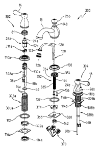
With reference now to Figs. 14 and 15, a further illustrative embodiment
faucet
assembly 300 is shown. The faucet assembly 300 includes many similar
components to
those detailed above in the widespread faucet assembly 10 of Fig. 1 and the
mini-
widespread faucet assembly 200 of Fig. 8. In the following description of the
faucet
assembly 300 of Figs. 14-21, components similar to those identified with
respect to the
faucet assembly 10 of Fig. 1 and faucet assembly 200 of Fig. 8 will be
identified with like
reference numbers.
In the illustrative embodiment of Figs. 14, 15, and 21, the hot and cold water
control handles 14 and 16 are illustratively coupled to hot and cold water
control
DIDDBO 1 5704643v1
CA 02727475 2010-12-09
WO 2009/158498
PCT/US2009/048658
-13-
assemblies 302 and 304, respectively. Each water control assembly 302 and 304
is
substantially identical. As such, in the following description reference will
be made
primarily to the hot water control assembly 302, with the understanding that
the cold
water control assembly 304 is substantially the same, except for the relative
orientation of
certain components (Figs. 14, 15, and 21). Similar components of the hot water
control
assembly 302 and the cold water control assembly 304 may be identified with
like
reference numbers followed by the suffix "a" and "b", respectively.
Similar to the faucet assemblies 10 and 200, in the faucet assembly 300 each
control assembly 302 and 304 includes a waterway 328 fluidly coupled to a
valve
cartridge 26. As detailed above, the base 330 of each waterway 328 may be
overmolded
around the ends 32 and 34 of the supply conduit 36 and the outlet conduit 38.
Each valve body or mounting shank 306 includes a substantially cylindrical
sidewall 308. Illustratively, the valve body 306 is formed of metal, such as
brass. The
valve body 306 has a bore 310 extending therethrough and defining a ledge or
annular lip
312 supporting the base 330 of the waterway assembly 328 (Figs. 16, 17, and
20). More
particularly, a coupler, illustratively a support clip 314, operably couples
the base 330 to
the valve body 306. The support clip 314 includes a body 315 having first and
second
retainers 316 and 318, respectively. Illustratively, the support clip 314 is
formed of a
polymer, such a polyatnide, and the retainers 316 and 318 are integral with
the body 315.
In one illustrative embodiment, the support clip 314 is molded from a glass
fiber
reinforced polyamide resin, such as Zytele 77G33L available from DuPont
Engineering
Polymers of Wilmington, Delaware.
As shown in Figs. 16-20, the first retainers 316 of the support clip 314
illustratively include a pair of diametrically opposed resilient arms 319
extending
outwardly from the body 315 and which are configured to snap into an annular
groove
320 machined into the sidewall 308 of the valve body 306. The retainers 316
are
illustratively biased outwardly from the base 330. Each arm 319 is
illustratively angled to
facilitate insertion into the groove 320, and includes a retaining ledge or
lip 324 to prevent
removal therefrom. Such engagement will keep the base 330 from being pushed
out of
the body 306 if the valve cartridge 26 is removed for service and the conduits
36, 38 are
coiled and pushed upward after being installed.
BDDB01 5704643v1
CA 02727475 2010-12-09
WO 2009/158498
PCT/US2009/048658
-14-
The second retainers 318 of the support clip 314 illustratively comprises a
pair of
diametrically opposed slots 332 for slidably receiving tabs 334 formed near a
lower end of
the base 330. The body 315 of the support clip 314 is substantially U-shaped
and defines
an open end 336 for receiving the base 330 of the waterway 328. The tabs 334
of the
base 330 cooperate with the slots 332 to facilitate proper rotational
alignment or
orientation of the waterway 28 relative to the support clip 314. As with base
230, base
330 may comprise a polymer overmolded around the ends 32 and 34 of the supply
conduit 36 and the outlet conduit 38. The tabs 334 are illustratively
integrally formed as
part of the overmold of base 330. As further detailed herein, each valve
cartridge 26
includes diametrically opposed alignment tabs or keys 92 which are received
within
cooperating recesses or notches 94 formed at the upper end 60 of the valve
body 306,
such that the handle 14 is properly aligned for use (Fig. 15).
With further reference to Figs. 16-20, orientation members 340 and 342
illustratively cooperate to facilitate proper rotational alignment or
orientation of the base
330 of the waterway 328 relative to the valve body 306. In the illustrative
embodiment,
orientation member 340 includes a pair of diametrically opposed protrusions or
projections 344 extending downwardly from the body 315 of the support clip
314. The
projections 344 engage in a pair of diametrically opposed recesses 346 formed
in the
sidewall 308 of the valve body 306 and defming orientation member 342. As
such, the
base 330 of the waterway 328 is rotationally keyed to the support clip 314
and,
subsequently to the valve body 306.
Referring further to Figs. 14, 15, and 21, a mounting member or shank 352
includes a flange 354 for mounting to the spout 18 through the use of
fasteners 136, such
as screws, while retaining fmish flange or escutcheon 138. The spout 18 is
illustratively
secured to the deck 12 through the use of a washer 360 and a nut 142
threadably
engaging external threads 144 on a downwardly extending tubular portion 365 of
the
mounting shank 352. The flange 354 includes a recess or notch 364 (Fig. 15)
configured
to position the outlet conduit 120 relative to a lift rod 148, which is
received within the
tubular portion 365 of the mounting shank 352 and is operably coupled to a
conventional
pop-up drain assembly (not shown). In a similar manner, the washer 360
illustratively
includes a notch 366 to position the outlet conduit 120 relative to the
tubular portion 365
of the mounting shank 352. In certain illustrative embodiments, the flange 354
and/or
13DDBOI 5704643N,1
CA 02727475 2013-05-03
-15-
washer 360 may include multiple notches 364 and/or 366, respectively, to
provide
flexibility in placement of the outlet conduit 120.
The inlet end 128 of the outlet conduit 120 is in fluid communication with the
hot
and cold water supply conduits 38a and 38b through a connector 370. The
connector 370
may be similar to connector 130 as detailed herein. In certain illustrative
embodiments,
the connector 370 may be a W fitting available from John Guest International
Ltd.
With reference to Figs. 15 and 21, optional spacers or bushings 372a, 372b may
be positioned within the mounting openings 58a, 58b of the sink deck 12 to
assist in
centering of the valve bodies 306a, 306b, and therefore the water control
assemblies 302,
304, relative to openings 58a, 58b. Similarly, a spacer or bushing 374 may be
positioned
within mounting opening 58c of the sink deck 12 to assist in centering of the
tubular
portion 365 of the mounting shank 352, and therefore the spout 18, relative to
opening
58c. Bushings 372 and 374 would generally be used only when the respective
mounting
openings 58 within the sink deck 12 are oversized.
Although the invention has been described in detail with reference to certain
preferred embodiments, the scope of the claims should not be limited by the
preferred
embodiments set forth in the examples, but should be given the broadest
interpretation
consistent with the description as a whole.