Note: Descriptions are shown in the official language in which they were submitted.
CA 02727491 2010-12-09
WO 2009/152026 PCT/US2009/046242
SURFACE COLOR PATTERNING WHILE DRAWING POLYMER ARTICLES
Cross Reference Statement
This application claims the benefit of U.S. Provisional Application No.
61/060,265,
filed June 10, 2008.
BACKGROUND OF THE INVENTION
Field of the Invention
The present invention relates to an oriented polymer composition and a process
for
producing oriented polymer compositions.
Description of Related Art
There is a desire to prepare polymer articles having color patterns that
create
decorative appearances such as natural wood grain in or on the polymer
articles.
One way to achieve natural wood grain patterns with colorants is by processing
a
base resin and a color concentrate together in an extruder and then extruding
the mixture
(see, for example, United States patents (USPs) 4048101; 4280950; 5387381; and
PCT
publication WO 97/04019). Such a process produces an extruded product having
colorant
dispersed throughout the resulting polymer composition. Having colorant
dispersed
throughout the polymer composition is desirable to provide depth to the
colorant pattern so
that the pattern survives scuffs and abrasion of the polymer composition's
surface (see, for
example, the discussion of disadvantages of prior art in USP 4280950 at column
1,
lines 21-24). On the other hand, having colorant dispersed throughout the
polymer
composition is inefficient since much of the colorant is internal to the
composition and
serves no purpose. Furthermore, mixing colorant with a base polymer in an
extruder affords
little if any control defining colorant placement and patterns (see, for
example, USP
5387381 at column 2, lines 7-12). Precise placement of colorant patterns is
difficult, if even
possible, in such a process. Therefore, there is opportunity to increase
efficiency and
control over the addition of colorant to polymer compositions to create
decorative designs.
One type of article that would benefit from optimizing addition of colorant to
create
a decorative appearance, especially that of a natural wood grain pattern, is
an oriented
polymer composition (OPC). An OPC comprises polymers oriented primarily in a
single
direction. An OPC has a higher strength and flexural modulus than the same
polymer
composition before orientation. The higher strength and flexural modulus of
OPCs make
-1-
CA 02727491 2010-12-09
WO 2009/152026 PCT/US2009/046242
them ideal for structural applications such as siding, decking, fencing and
flooring, which
typically utilize wood.
Two publications report applying to the surface of an orientable polymer
composition ink markings that remain after orientation to an OPC. The markings
are for
determining the linear draw ratio of the drawing process (see, W.R. Newson and
F.R.
Maine, ORIENTED POLYPROPYLENE COMPOSITIONS MADE WITH MICA and
W.R. Newson and F.R. Maine, ORIENTED POLYPROPYLENE COMPOSITES MADE
WITH CALCIUM CARBONATES, both are handouts from 8`h International Conference
on
Woodfiber-Plastic Composites, Madison, Wisconsin, May 23-25, 2005). These
references
describe measuring the extension of ink markings on the surface of a polymer
composition
to determine linear draw ratio after drawing the polymer composition. The
linear draw ratio
is the ratio of the length of the elongated marking after drawing to the
length of the marking
prior to drawing. As explained later with discoveries of the present
invention, the marking
is likely a straight line with negligible width and that extends the drawing
direction of the
OPC or determination of an accurate linear draw ratio would be difficult if
possible. It is
desirable to produce colorant patterns more exotic and visually interesting
than elongated
lines on an OPC, and to create the colorant patterns that have greater wear
resistance than a
mere marking on a surface of an OPC.
A process for producing an OPC having a decorative pattern, particularly a
natural
wood grain pattern, is desirable. Further desirable is such a process that
efficiently uses
colorant and allows precise control over the placement of colorant in a
polymer
composition. Yet more desirable is such a process that provides an OPC having
a
decorative pattern that benefits from greater wear-resistance than achievable
by applying an
ink marking to a surface of a polymer composition.
BRIEF SUMMARY OF THE INVENTION
The present invention advances the art of oriented polymer compositions by
providing a process for producing OPC having decorative colorant patterns that
allows
efficient use of colorant, control over the placement of colorant, benefits
from
inhomogeneous drawing of a polymer composition and/or that can provide an OPC
having
a decorative pattern having greater wear-resistance than achievable by
applying an ink
marking to a surface of a polymer composition.
-2-
CA 02727491 2010-12-09
WO 2009/152026 PCT/US2009/046242
In one regard, the present invention advances the art of oriented polymer
compositions by providing a process for producing an oriented polymer
composition (OPC)
having greater control over decorative patterns than prior art processes.
Unlike prior
processes used to create decorative patterns on polymer compositions,
particularly OPCs,
the present process allows the ability to directly dispose colorant in
specific locations on or
in an orientable polymer to create specific colorant patterns in a final OPC.
In a second regard, the present invention surprisingly enables an artisan to
preferentially locate colorant proximate to a surface of the OPC so wasteful
blending of a
colorant into a base resin is unnecessary.
In yet another regard, research leading to the present invention revealed a
surprising
result that drawing non-cylindrical polymer articles facilitates achieving non-
homogeneous
polymer movement during drawing and achieving decorative colorant patterns on
an OPC,
particularly patterns that resemble natural-wood. It became apparent that
desirable
distortions of colorant patterns can occur by inhomogeneous drawing of a
polymer
composition. For example, drawing an orientable polymer composition having a
rectangular cross section with colorant extending in a straight line across
the width of the
orientable polymer composition has a tendency to cause the straight line to
distort into a
chevron-like pattern that simulates wood grain in a flat sawn (or nearly flat
sawn) wooden
board. Other distortions are also possible depending on the shape of the
orientable polymer
composition and conditions of drawing the orientable polymer composition.
Figures la and lb illustrate this surprising result of inhomogeneous surface
polymer
displacement during drawing. Figure la illustrates a major surface of a
polymer
composition that has a rectangular cross section prior to drawing the polymer
composition.
The major surface has ink lines extending across the major surface
perpendicular to the
drawing direction. The ink lines were drawn as straight lines extending across
the
orientable polymer composition prior to going through a calibrator. The lines
became
slightly distorted to a chevron-like shape even through the calibrator. Figure
lb illustrates
one of those same lines after drawing the polymer composition through a
drawing die and
reveals that the lines have been distorted to form a chevron-like pattern with
the portion of
line more proximate to the centroid of a cross section of the polymer
composition (which
coincides with being central to the width of the board) further along in the
drawing
direction than portions of the lines more remote from the centroid of the
cross section
-3-
CA 02727491 2010-12-09
WO 2009/152026 PCT/US2009/046242
(coinciding with being closer to the edges of the surface). Moreover, the line
is spread
apart more proximate to the center of the surface (most proximate to the
centroid of the
cross section) than portions of the line closer to the edges of the surface
(less proximate to
the centroid of the cross section). This inhomogeneous displacement of surface
polymer is
particularly useful in creating non-linear color patterns including exotic
surface color
patterns, especially wood grain patterns. Notably, flat sawn, or nearly flat
sawn wooden
boards tend to have grain patterns that are chevron shaped color patterns
having a peak and
tails wherein the color pattern is broader towards the peak than the tails
(see, for example,
Figure 2 that illustrates the grain pattern in a board of ash wood). Polymer
motion through
the calibrator and drawing die is to the right in Figures la and lb.
Discovery of this surprising result requires drawing a polymer composition
that has a
surface marking with sufficient breadth in a dimension perpendicular to the
drawing
direction (that is, sufficient width) to reveal inhomogeneity in polymer
displacement.
Research (see Example 2 below) reveals that such a width is generally at least
five
millimeters. As a result, it is unlikely the markings described in prior art
to determine
linear draw ratio have sufficient width to have revealed the inhomogeneity in
polymer
displacement and the references make no mention of such a surprising result
(see, W.R.
Newson and F.R. Maine, ORIENTED POLYPROPYLENE COMPOSITIONS MADE
WITH MICA and W.R. Newson and F.R. Maine, ORIENTED POLYPROPYLENE
COMPOSITES MADE WITH CALCIUM CARBONATES, both are handouts from 8`h
International Conference on Woodfiber-Plastic Composites, Madison, Wisconsin,
May 23-25, 2005).
In still yet another regard, the process of the present invention advances the
prior art
by providing an OPC having colorant that is preferentially proximate to a
surface of the
OPC while still achieving scuff, scratch and wear resistance beyond that of a
colorant
merely disposed on a surface of the OPC. The process provides a method for
embedding
the colorant into the orientable polymer composition through a surface so that
the colorant
penetrates into the polymer composition below the polymer composition's
surface and
produces an OPC having a color pattern that tends to be more wear-resistant
(for example,
greater durability through repeated abrasion) than an OPC having a color
pattern only on its
surface.
-4-
CA 02727491 2010-12-09
WO 2009/152026 PCT/US2009/046242
In a first aspect, the present invention is a process for preparing an
oriented polymer
composition comprising the steps of : (a) providing a calibrator, a colorant,
and an
orientable polymer composition that has a surface, softening temperature and a
width ;
(b) extruding the orientable polymer composition at a temperature above the
orientable
polymer composition's softening temperature; (c) directing the orientable
polymer
composition through a calibrator; (d) conditioning the orientable polymer
composition to a
drawing temperature at which the polymer composition is in a solid state; and
(e) initiating
drawing of the orientable polymer composition while the orientable composition
is in a
solid state and drawing the orientable polymer composition into an oriented
polymer
composition; wherein step (d) occurs during or after step (c) but occurs prior
to step (e) and
further comprising a step of adding a colorant to one or more than one surface
of the
orientable polymer composition in one or both of the following places in the
process:
(i) after exiting the extruder and before exiting the calibrator; and (ii)
after exiting the
calibrator and before completion of the drawing step; and wherein the colorant
is part of a
colorant pattern that has a width of at least five millimeters.
Desirable embodiments of the first aspect include any one or any physically
possible
combination of more than one of the following further characteristics:
addition of colorant
during (i) occurs prior to the calibrator; drawing in step (e) includes
drawing the orientable
polymer composition through a drawing die wherein the orientable polymer
composition is
in a solid state as it enters the drawing die and addition of colorant during
(ii) occurs prior
to a drawing die; the step of adding colorant to a surface includes directly
impressing
colorant into the surface so that the colorant resides in a recessed portion
of the orientable
polymer composition's surface; at least a portion of the colorant becomes
embedded into
the orientable polymer composition so as to extend to a depth below the
surface of the
orientable polymer composition to which it was added of at least one
millimeter in the
resulting oriented polymer composition; the colorant resides exclusively
within five
millimeters of a surface of the oriented polymer composition; the orientable
polymer
composition and oriented polymer composition are non-cylindrical; step (c)
continuously
follows step (b) and steps (d) and (e) continuously follow step (c); step (c)
continuously
follows step (b) and colorant is added to at least one surface of the
orientable polymer
composition between steps (b) and (c); the colorant resides at least partially
above the
surface of the orientable polymer composition before the orientable polymer
composition
-5-
CA 02727491 2010-12-09
WO 2009/152026 PCT/US2009/046242
goes through the calibrator; the colorant comprises a pigment in a carrier
wherein the
carrier is selected from a group consisting of a thermoplastic polymer matrix,
organic
liquids, organic solvents, aqueous liquids and aqueous solvents; the colorant
comprises a
pigment in a thermoplastic polymer matrix; the colorant is adhesively
compatible with the
orientable polymer composition; drawing in step (e) occurs at such a rate that
necking of
the orientable polymer composition is complete while the orientable polymer
composition
has cross sectional dimensions that all exceed two millimeters; and addition
of the colorant
comprises applying colorant in a non-linear pattern.
In a second aspect, the present invention is an oriented polymer composition
comprising an orientable polymer composition and a colorant; wherein the
oriented
polymer composition has at least one surface and a core, and a dimension of
primary
orientation and wherein the colorant is part of a colorant pattern having a
width of at least
five millimeters.
Desirable embodiments of the second aspect include any one or any physically
possible combination of more than one of the following further
characteristics: at least a
portion of the colorant resides in a recessed portion of the orientable
polymer
composition's surface; at least a portion of the colorant extends to a depth
of at least one
millimeter below a surface of the oriented polymer composition and is
preferentially
located proximate to the surface of the oriented polymer composition as
opposed to the
core of the oriented polymer composition; colorant is exclusively located
within five
millimeters of at least one surface of the oriented polymer composition; the
colorant is
adhesively compatible with the orientable polymer composition; the oriented
polymer
composition is non-cylindrical; and the colorant forms a non-linear pattern.
The process of the present invention is useful for manufacturing the OPC of
the
present invention. The OPC of the present invention is useful for structural
applications
such as decking materials (for example, deck boards, railings, and decorative
trim), siding
materials, fencing and flooring.
BRIEF DESCRIPTION OF THE DRAWINGS
Figures la and lb illustrate what were straight lines drawn perpendicular to
the flow
or drawing direction on an orientable polymer composition prior to entering a
calibrator
and reveals inhomogeneous distortion of the lines after passing through a
calibrator and
drawing die. Figure la illustrates distortion of the lines after exiting the
calibrator. Figure
-6-
CA 02727491 2010-12-09
WO 2009/152026 PCT/US2009/046242
lb illustrates distortion of the lines after further undergoing drawing.
Drawing direction is
to the right.
Figure 2 illustrates wood grain of a board of Ash wood.
Figure 3 illustrates a schematic layout of an embodiment of a continuous
process of
the present invention.
Figure 4 illustrates elongation of straight lines extending in the drawing
direction
drawn on an orientable polymer composition after a calibrator and prior to
drawing.
Drawing direction is to the left.
DETAILED DESCRIPTION OF THE INVENTION
"ASTM" refers to American Society for Testing and Materials. The ASTM test
methods described herein refer to the test method of the year designated by
the hyphenated
suffix or, in an absence of a hyphenate suffix, the most recent test method as
of the priority
date of the present specification.
"Solid state" refers to a polymer (or polymer composition) that is below the
softening temperature of the polymer (or polymer composition). Hence, "solid
state
drawing" refers to drawing a polymer or polymer composition that is at a
temperature below
the softening temperature of the polymer (or polymer composition).
"Polymer composition" comprises at least one polymer component and can contain
non-polymeric components. A polymer composition has at least one surface, a
core, and a
softening temperature.
"Cylindrical" refers to an article having a circular cross section.
"Non-cylindrical" refers to an article or composition that has a non-circular
cross
section. Desirably, an oriented polymer composition that is non-cylindrical
within the scope
of the present invention has a maximum cross sectional aspect ratio that is
two or more,
preferably three or more and can be five or more, ten or more, even twenty or
more.
Typically, an oriented polymer composition within the scope of the present
invention has a
maximum cross sectional aspect ratio that is 100 or less, preferably 50 or
less, more
preferably 25 or less and can be twenty or less, even ten or less.
"Cross sections" of an oriented polymer composition are perpendicular to the
drawing axis of the oriented polymer composition unless the reference to the
cross section
indicates otherwise. A cross section has a centroid and a perimeter that
defines a shape for
the cross section.
-7-
CA 02727491 2010-12-09
WO 2009/152026 PCT/US2009/046242
"Drawing axis" is a straight line through an oriented polymer composition that
is
parallel to the direction of primary alignment of the polymers in the oriented
polymer
composition. When an orientable polymer composition is drawn in only one
direction the
drawing axis extends in the direction that the center of mass (centroid) of
the polymer
composition is moving as the polymer composition is drawn in a solid state
drawing
process.
A "cross sectional dimension" is the length of a straight line connecting two
points
on a cross section's perimeter and extending through the centroid of the cross
section. For
example, a cross sectional dimension of a rectilinear four-sided polymer
composition could
be the height or width of the polymer composition.
"Surface" of a polymer composition refers to that portion of the polymer
composition that interfaces with the environment surrounding the polymer
composition.
Generally, a polymer composition is considered to have more than one surface,
with each
surface distinguished from another surface by an edge. A sphere, for example,
has a single
surface and is free of edges. A rectangular box, on the other hand, has six
surfaces and 12
edges.
"Major surface" refers to a surface having a planar surface area equal to or
greater
than that of any other surface of an article.
"Planar surface area" is the surface area as projected onto a plane and serves
to take
into account the surface area without accounting for peaks, valleys or
cavities in the surface.
"Core" of a polymer composition is a three dimensional centroid for the
polymer
composition. When viewing a cross section of a polymer composition the surface
defines
the perimeter of the cross section while the core is the centroid of the cross
section.
"Softening temperature" (TS) for a polymer or polymer composition having as
polymer components only one or more than one semi-crystalline polymer is the
melting
temperature for the polymer composition.
"Melting temperature" (Tm) for a semi-crystalline polymer is the temperature
half-
way through a crystalline-to-melt phase change as determined by differential
scanning
calorimetry (DSC) upon heating a crystallized polymer at a specific heating
rate. Determine
Tm for a semi-crystalline polymer according to the DSC procedure in ASTM
method E794-
06. Determine Tm for a combination of polymers and for a filled polymer
composition also
by DSC under the same test conditions in ASTM method E794-06. If the
combination of
-8-
CA 02727491 2010-12-09
WO 2009/152026 PCT/US2009/046242
polymers or filled polymer composition only contains miscible polymers and
only one
crystalline-to-melt phase change is evident in its DSC curve, then Tm for the
polymer
combination or filled polymer composition is the temperature half-way through
the phase
change. If multiple crystalline-to-melt phase changes are evident in a DSC
curve due to the
presence of immiscible polymers, then Tm for the polymer combination or filled
polymer
composition is the Tm of the continuous phase polymer. If more than one
polymer is
continuous and they are not miscible, then the Tm for the polymer combination
or filled
polymer composition is the lowest Tm of the continuous phase polymers.
"Softening temperature" (TS) for a polymer or polymer composition having as
polymer components only one or more than one amorphous polymer is the glass
transition
temperature for the polymer composition.
"Glass transition temperature" (Tg) for a polymer or polymer composition is as
determined by DSC according to the procedure in ASTM method E1356-03.
Determine Tg
for a combination of polymer and for a filled polymer composition also by DSC
under the
same test conditions in ASTM method E1356-03. If the combination of polymer or
filled
polymer composition only contains miscible polymers and only one glass
transition phase
change is evident in the DSC curve, then Tg of the polymer combination or
filled polymer
composition is the temperature half-way through the phase change. If multiple
glass
transition phase changes are evident in a DSC curve due to the presence of
immiscible
amorphous polymers, then Tg for the polymer combination or filled polymer
composition is
the Tg of the continuous phase polymer. If more than one amorphous polymer is
continuous
and they are not miscible, then the Tg for the polymer composition or filled
polymer
composition is the lowest Tg of the continuous phase polymers.
If the polymer composition contains a combination of semi-crystalline and
amorphous polymers, the softening temperature of the polymer composition is
the softening
temperature of the continuous phase polymer or polymer composition. If the
semi-
crystalline and amorphous polymer phases are co-continuous, then the softening
temperature
of the combination is the lower softening temperature of the two phases.
"Drawing temperature" is a temperature within a drawing temperature range at
which a polymer is conditioned prior to drawing and is the temperature at
which the
polymer exists upon the initiation of drawing.
-9-
CA 02727491 2010-12-09
WO 2009/152026 PCT/US2009/046242
An artisan understands that a polymer composition typically has a variation in
temperature through its cross section (that is, along a cross sectional
dimension of the
composition) during processing. Therefore, reference to temperature of a
polymer
composition refers to an average of the highest and lowest temperatures along
a cross
sectional dimension of the polymer composition. The temperature at two
different points
along the polymer cross sectional dimension desirably differs by 10 percent
(%) or less,
preferably five % or less, more preferably one % or less, most preferably by
0% from the
average temperature of the highest and lowest temperature along the cross
sectional
dimension. Measure the temperature in degrees Celsius ( C) along a cross
sectional
dimension by inserting thermocouples to different points along the cross
sectional
dimension.
Drawing Process and Oriented Polymer Composition
One aspect of the present invention is a process for preparing an oriented
polymer
composition (OPC) from an orientable polymer composition and in another aspect
the
present invention is an OPC. The OPC and the orientable polymer composition
each
comprises a continuous phase of orientable polymer. Typically, 75 weight-
percent (wt%) or
more, even 90 wt% or more or 95 wt% or more of the polymers in an OPC and
orientable
polymer composition are orientable polymers. The orientable polymers of an OPC
are
preferentially aligned along a single axis, which give rise to the term
"oriented". The
oriented nature of the polymers in an OPC provides desirable characteristics
to an OPC over
a non-oriented polymer composition including increased flexural modulus and
strength.
An orientable polymer is a polymer that can undergo induced molecular
orientation
by solid state deformation (for example, solid state drawing). An orientable
polymer can be
amorphous or semi-crystalline (semi-crystalline polymers have a melt
temperature (Tm) and
include those polymers known as "crystalline"). Desirable orientable polymers
include
semi-crystalline polymers, even more desirable are linear polymers (polymers
in which
chain branching occurs in less than 1 of 1,000 polymer units). Semi-
crystalline polymers
are particularly desirable because they result in greater increase in strength
and modulus
than amorphous polymer compositions. Semi-crystalline polymer compositions can
result
in 4-10 times greater increase in strength and flexural modulus upon
orientation over
amorphous polymer compositions.
-10-
CA 02727491 2010-12-09
WO 2009/152026 PCT/US2009/046242
Suitable orientable polymers include polymers and copolymers of polystyrene,
polypropylene, polyethylene (including high density polyethylene),
polymethylpentane,
polytetrafluoroethylene, polyamides, polyesters such as polyethylene
terephthalate and
polybutylene terephthalate, polycarbonates, polyethylene oxide,
polyoxymethylene and
blends thereof. Particularly desirably orientable polymers include
polyethylene,
polypropylene, and polyesters. More particularly desirable orientable polymers
include
linear polyethylene having a weight-average molecular weight from 50,000 to
3,000,000;
especially from 100,000 to 1,500,000, even from 750,000 to 1,500,000.
Polyvinylidene
fluoride polymers having a weight-average molecular weight of from 200,000 to
800,000,
preferably 250,000 to 400,000 are also suitable. Another desirable polymer is
high density
polyethylene having a density in a range of 0.941 to 0.959 grams per cubic
centimeters and a
weight-average molecular weight of 110,000 grams per mole or higher,
preferably 156,000
grams per mole or higher, yet more preferably 190,000 grams per mole or
higher. Such a
high density polyethylene is particularly conducive to high drawing speeds
without
breaking.
Polypropylene (PP)-based polymers are especially desirable for use in the
present
invention. PP-based polymers generally have a lower density than other
orientable polymers.
Therefore, PP-based polymers facilitate lighter articles than other orientable
polymers.
Additionally, PP-based polymers offer greater thermal stability than other
orientable olefin
polymers. Therefore, PP-based polymers may also form oriented articles having
higher
thermal stability than oriented articles of other polymers.
Suitable PP-based polymers include Zeigler Natta, metallocene and post-
metallocene
polypropylenes. Suitable PP-based polymers include PP homopolymer; PP random
copolymer (with ethylene or other alpha-olefin present from 0.1 to 15 percent
by weight of
monomers); PP impact copolymers with either PP homopolymer or PP random
copolymer
matrix of 50-97 percent by weight (wt%) based on impact copolymer weight and
with
ethylene propylene copolymer rubber present at 3-50 wt% based on impact
copolymer
weight prepared in-reactor or an impact modifier or random copolymer rubber
prepared by
copolymerization of two or more alpha olefins prepared in-reactor; PP impact
copolymer
with either a PP homopolymer or PP random copolymer matrix for 50-97 wt% of
the impact
copolymer weight and with ethylene-propylene copolymer rubber present at 3-50
wt% of the
impact copolymer weight added via compounding, or other rubber (impact
modifier)
-11-
CA 02727491 2010-12-09
WO 2009/152026 PCT/US2009/046242
prepared by copolymerization of two or more alpha olefins(such as ethylene-
octene)by
Zeigler-Natta, metallocene, or single-site catalysis, added via compounding
such as but not
limited to a twin screw extrusion process.
The PP-based polymer can be ultra-violet (UV) stabilized, and desirably can
also be
impact modified. Particularly desirable PP-based polymers are stabilized with
organic
stabilizers. The PP-based polymer can be free of titanium dioxide pigment to
achieve UV
stabilization thereby allowing use of less pigment to achieve any of a full
spectrum of
colors. A combination of low molecular weight and high molecular weight
hindered amine-
type light stabilizers (HALS) are desirable additives to impart UV
stabilization to PP-based
polymers. Suitable examples of commercially available stabilizers include
IRGASTABTM
FS 811, IRGASTABTM FS 812 (IRGASTAB is a trademark of Ciba Specialty Chemicals
Corporation). A particularly desirable stabilizer system contains a
combination of
IRGASTABTM FS 301, TINUVINTM 123 and CHIMASSORBTM 119. (TINUVIN and
CHIMASSORB are trademarks of Ciba Specialty chemicals Corporation).
The orientable polymer composition, as well as OPC of the present invention,
may
contain fillers including organic, inorganic or a combination of organic and
inorganic fillers.
It is desirable for inorganic fillers to account for 50 volume percent (vol%)
or more,
preferably 75 vol% or more, and most preferably 100 vol% of the total volume
of filler.
Inorganic fillers are more desirable than organic fillers for numerous reasons
including that
inorganic fillers tend to be more thermally stable and resistant to decay and
discoloration.
The fillers, if present, exist dispersed within, preferably throughout the
entire orientable
polymer composition and OPC.
Suitable organic fillers include cellulosic materials such as wood flour, wood
pulp,
flax, rice hulls or any natural fiber. Rubber particles are also suitable
organic filler.
Suitable inorganic filler include mica, talc (including any or a combination
of materials and
grades commonly known and available as "talc"), chalk, titanium dioxide, clay,
alumina,
silica, glass beads, calcium carbonate, magnesium sulfate, barium sulfate,
calcium
oxysulfate, tin oxide, metal powder, glass powder, pigments, minerals, glass,
ceramic,
polymeric or carbon reinforcing agents, glass fibers, carbon fibers,
wollastonite, graphite,
magnesium carbonate, alumina, metal fibers, kaolin, silicon carbide, and glass
flake.
Fillers can serve many purposes including serving to enhance flame retardancy,
induce cavitation during the drawing process, and provide partial
reinforcement of an
-12-
CA 02727491 2010-12-09
WO 2009/152026 PCT/US2009/046242
article. Inorganic fillers are more desirable than organic fillers in the
present invention
because organic fillers can undergo charring, and associated discoloration,
upon heating a
surface of the cavitated OPC to form a de-oriented longitudinal surface layer.
Organic
fillers also tend to fade over time with exposure to ultraviolet radiation.
The orientable polymer composition, and hence, the resulting OPC, can further
contain additives that enhance flame retardancy, foaming agents, or any other
additives
common to plastic processing.
The orientable polymer composition has a softening temperature. In an
embodiment
of the present invention, extrude an orientable polymer composition at a
temperature above
the orientable polymer composition's softening temperature. Direct the
orientable polymer
composition through a calibrator. Ideally, the calibrator smoothes the surface
or surfaces of
the orientable polymer composition. In a desirable embodiment, cool the
surface of the
orientable polymer composition within the calibrator to a temperature below
the orientable
polymer composition's softening temperature in order to stabilize the shape of
the orientable
polymer composition sufficiently to enable the orientable polymer composition
to retain its
shape without deformation as it travels from the calibrator. Typically, the
calibrator cools
the orientable polymer composition sufficiently to create a skin around the
orientable
polymer composition ("around" meaning sufficient to exist around a cross
sectional
circumference) that is at a temperature equal to or below T. The skin
desirably extends
from the orientable polymer composition's surface to a depth of 0.5
millimeters (mm) or
more, preferably one mm or more to create a cooled skin around the orientable
polymer
composition (around a cross sectional circumference). The necessary depth of
cooling
depends on the total dimensions of the orientable polymer composition, with
orientable
polymer compositions having larger cross sections requiring a thicker cooled
skin.
Sufficient cooling is achieved if the polymer composition remains of constant
shape upon
exiting the calibrator and prior to any further manipulation, such as drawing.
A calibrator has a calibrator channel that extends through the calibrator from
one end
through an opposing end. The calibrator channel comprises a land-type section
that defines
and holds the shape of the orientable polymer composition, preferably as the
orientable
polymer composition cools. The calibrator channel typically comprises a flared
entrance
opening into which the orientable polymer composition enters the calibrator
prior to the
-13-
CA 02727491 2010-12-09
WO 2009/152026 PCT/US2009/046242
land-type section. The land-type section is essentially uniform in cross
sectional area and
shape and is desirably long enough to house the orientable polymer composition
as it cools.
It is desirable for the calibrator to continuously follow an extruder so that
an
orientable polymer composition may continuously proceed from the extruder
through the
calibrator. The calibrator may be attached to the extruder or be remote from
the extruder.
Desirably, the position of the calibrator relative to the extruder allows for
addition of
colorant to a polymer composition between the extruder and calibrator.
Therefore, if the
calibrator is attached to the extruder there is desirably an opening to allow
disposition of
colorant onto one or more surface of an orientable polymer composition between
the
extruder and calibrator, within the end of the extruder or within the entrance
to the
calibrator. Preferably, the calibrator is distinct from the extruder, meaning
there is a space
between the extruder and calibrator that extends all the way around the
circumference of an
orientable polymer composition traveling between the extruder and calibrator.
Such an
orientation provides access, preferably unhindered access to any portion of
the orientable
polymer composition's surface for addition of colorant.
After the orientable polymer composition exits the calibrator, orient the
orientable
polymer composition to form an OPC by solid state drawing the orientable
polymer
composition at a drawing temperature. Draw the orientable polymer composition
by
applying tensile force to the orientable polymer composition that is of
sufficient force to
cause the orientable polymer composition to narrow in cross sectional area but
not so high
in force as to cause the orientable polymer to break (that is, to exceed the
tensile strength of
the orientable polymer composition). The direction of tensile force defines
the drawing axis
and drawing direction of the orientable polymer composition.
Drawing may occur continuously after the calibrator, meaning an orientable
polymer
composition may proceed as a continuous material from the calibrator through
the drawing
process. Alternatively, drawing may occur discontinuously from the rest of the
process,
meaning the orientable polymer may be drawn remote in time and/or location
from when it
was extruded and calibrated. For example, drawing of an orientable polymer
composition
can occur minutes, hours, days, weeks, months even years after exiting a
calibrator. When
drawing is discontinuous with calibrating, billets of orientable polymer
composition are
generally cut to a desired length after the calibrator and stored until drawn.
Desirably,
drawing occurs continually after the calibrator to maximize process
efficiency.
-14-
CA 02727491 2010-12-09
WO 2009/152026 PCT/US2009/046242
Drawing may occur as a solid state free-drawing process, solid state die-
drawing
process, roller-drawing process (drawing through moving rollers) or any
combination of
these processes. Drawing processes utilize a tensile force to pull a polymer
composition.
Solid state free-drawing occurs by applying to a solid state orientable
polymer composition
a tensile force that is sufficient to cause the orientable polymer composition
to elongate and
orient in a drawing direction free of physical constraints directing how the
cross section
necks during elongation. Solid state die-drawing occurs by applying a tensile
force to pull a
solid state orientable polymer composition through a converging die that
directs necking of
the orientable polymer composition as the orientable polymer composition
elongates and
orients. An orientable polymer composition in a solid state die-drawing
process can
undergo free-drawing after exiting a solid state drawing die and thereby
experience a
combination of die-drawing and free-drawing. An orientable polymer composition
may also
neck away from a drawing die while still within the drawing die, thereby
experiencing free-
drawing while still within the drawing die. It is most desirable to use a
solid state drawing
die in order to control the final cross sectional shape of the resulting OPC.
Even if some
free-drawing occurs after the solid state drawing die, the die generally will
direct the free
drawing and offer better control over final OPC dimensions than a free-draw
process that
does not use a solid state drawing die.
Suitable solid state drawing dies for use in the process of the present
invention
include any converging die. Desirably, the drawing die is a substantially
proportional die as
described in published U.S. patent application 2008-0111277 (incorporated
herein by
reference in its entirety). A substantially proportional die has a shaping
channel extending
entirely through it - that is, through and from one end of the die to and
through an opposing
end of the die. Orientable polymer composition travels through the shaping
channel. Each
cross section of the shaping channel is proportional to any other cross
section of the shaping
channel. Herein, "proportional" allows for some tolerance in interpretation
from being
perfectly proportional to any measurable extent. Instead, two cross sections
are still
"proportional" within the scope of the term herein if the cross sections have
deviations of
5% or less, preferably 3% or less, more preferably 1% or less from
proportional. Determine
percent deviation from proportional by dividing the ratio of two cross
sectional dimensions
for a smaller cross section by a ratio of the same cross sectional dimensions
for another
larger cross section, subtracting that value from one and multiplying by 100%.
-15-
CA 02727491 2010-12-09
WO 2009/152026 PCT/US2009/046242
It is desirable to draw the orientable polymer composition at a drawing
temperature
(Td) in a drawing temperature range of 0-50 C below the orientable polymer
composition's
T. Preferably, Td for an orientable polymer composition is 40'C or less, more
preferably
25 C or less, still more preferably 15 C or less below the orientable polymer
composition's
TS and can be one C or more, even five C or more below the orientable
polymer
composition's T. When using a solid state drawing die it is desirable to
maintain the die at
a temperature at or below TS of the orientable polymer composition being
drawn. It is also
desirable to maintain the orientable polymer composition at a drawing
temperature while
drawing the orientable polymer composition, particularly while the orientable
polymer
composition is in a solid state drawing die. An orientable polymer composition
is
"drawing" while it is contracting in cross sectional area ("necking") under a
tensile drawing
force.
Draw the orientable polymer composition at a drawing rate. Drawing rate is a
measure of linear distance the orientable polymer composition travels over
time. Generally,
the more an orientable polymer composition necks, cavitates or converges
during a drawing
process, the faster the drawing rate becomes. It is general practice to define
as the drawing
rate for an entire drawing process the fastest linear rate the orientable
polymer composition
experiences during the entire drawing process, which is typically the rate at
which the final
OPC is manufactured. This is the convention used herein unless otherwise
stated.
One of ordinary skill in the art understands that an orientable polymer
composition
may experience multiple local or intermediary drawing rates during an entire
drawing
process. For example, an orientable polymer composition may have one drawing
rate after a
drawing die and yet increase drawing rate by free-drawing after the drawing
die. Similarly,
an orientable polymer composition increases drawing rate as it experiences
free-drawing or
die-drawing. These processes can be construed as having variable drawing
rates.
Moreover, drawing can occur in multiple steps; thereby, experiencing multiple
intermediary
drawing rates. For example, using two different drawing dies in sequence will
produce at
least two different intermediary drawing rates, with the drawing rate after
the second
drawing die being faster than the drawing rate after the first die. All
conceivable
combinations and variations of drawing are within the scope of the present
invention. One
of ordinary skill in the art recognizes that an overall drawing process may
include multiple
intermediate drawing steps, each of which may have an intermediary drawing
rate that
-16-
CA 02727491 2010-12-09
WO 2009/152026 PCT/US2009/046242
corresponds to the fastest linear rate the orientable polymer composition
travels during that
intermediary drawing step. Intermediary drawing rates are equal to or less
than the drawing
rate for the entire process.
One desirable embodiment of the present invention is a solid state die-drawing
process that uses a drawing rate of 0.25 meter per minute (m/min) or faster,
preferably 0.5
m/min or faster, still more preferably two m/min or faster drawing rate.
Optimally, the
drawing rate is 1.2 m/min or faster, preferably 2.4 m/min or faster and still
more preferably
3.7 m/min or faster in order to maximize the ability to visually appreciate
colorant pattern
distortion due to inhomogeneous surface polymer displacement. An upper limit
for drawing
rate is limited only by the force necessary to achieve that drawing rate. The
drawing force
should not exceed the tensile strength at the drawing temperature of the
orientable polymer
composition being drawn otherwise the orientable polymer composition will
fracture.
Typically, the drawing rate is 30 m/min or slower.
The orientable polymer composition can undergo cavitation during the drawing
process and thereby decrease in density. Cavitation is a process by which void
volume
forms proximate to filler particles or crystallites in an orientable polymer
composition
during a drawing process as polymer is drawn away from the filler particle or
crystallite.
Cavitation is a means of introducing void volume into an orientable polymer
composition
(and, hence, OPC) without having to use a blowing agent. The extent of
cavitation that
occurs during drawing is dependent upon drawing rate as well as filler and
crystallite
concentration. Increasing any of drawing rate, filler concentration or
crystallite
concentration or decreasing drawing temperature generally increases the extent
of
cavitation. A desirable embodiment of the process of the present invention
induces
cavitation during the drawing step to produce an OPC of the present invention
that has
cavitation void volume (that is, a cavitated OPC).
In one respect, the process of the present invention differs from other
drawing
processes by including addition of a colorant to one or more than one surface
of the
orientable polymer composition between the steps of: (a) extruding the
orientable polymer
composition and (b) directing the orientable polymer composition out from a
calibrator; or
between steps (b) and (c) completing solid state drawing of the orientable
polymer
composition; or both between steps (a) and (b) as well as (b) and (c). In a
desirable
embodiment, colorant is added between steps (a) and (b) and can be added
exclusively
-17-
CA 02727491 2010-12-09
WO 2009/152026 PCT/US2009/046242
between steps (a) and (b). While colorant can be added to a polymer
composition while the
polymer composition is in a calibrator, preferably colorant is added to the
polymer
composition prior to entering the calibrator when adding colorant between
steps (a) and (b).
That way, the calibrator can serve to impress or embed the colorant at least
partially into the
orientable polymer composition. Similarly, colorant can be added to a polymer
composition
while the polymer composition is in a drawing die between steps (b) (c) in a
process using a
solid state drawing die; however, colorant is preferably added to the polymer
composition
before the polymer composition enters a drawing die when colorant is added
between steps
(b) and (c).
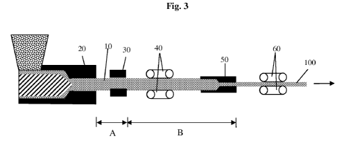
Figure 3 provides an illustration of an embodiment of a continuous process
within
the scope of the present invention that is useful for understanding where
colorant addition
can occur. Figure 3 illustrates orientable polymer composition 10 that exits
extruder 20 and
that travels through calibrator 30 with the assistance of haul off device 40.
After traveling
through haul off device 40, haul off device 60 applies sufficient tensile
force on orientable
polymer composition 10 to draw orientable polymer composition 10 through
drawing die 50
thereby drawing orientable polymer composition 10 into OPC 100. Addition of
colorant to
orientable polymer composition 10 can occur between steps (a) and (b), which
corresponds
to addition in any part or over the entire length of section A in Figure 3.
Alternatively, or
additionally, addition of colorant to orientable polymer composition 10 can
occur between
steps (b) and (c), which corresponds to addition in any portion or over the
entire length of
section B in Figure 3.
Adding colorant between steps (a) and (b) and, or in an alternative, between
steps (b)
and (c) in the process offers tremendous advantages over other colorant
addition methods,
such as blending colorant into the orientable polymer composition in an
extruder. One such
advantage is the ability to specifically control the positioning of colorant
in the orientable
polymer composition. An artisan may dispose colorant into specific patterns on
one or more
than one surface of an orientable polymer composition in the present process.
Such an
advantage allows precise control over colorant patterns and pattern size in or
on a final OPC
that is not achievable when colorant is blended into an orientable polymer
composition in an
extruder. Another advantage the present process offers over other processes is
that colorant
is specifically disposed proximate to one or more surface of an orientable
polymer
composition and remains proximate to the one or more surface as opposed to the
core of the
-18-
CA 02727491 2010-12-09
WO 2009/152026 PCT/US2009/046242
orientable polymer composition. That is, the colorant is preferentially
disposed proximate
to one or more surface of an orientable polymer composition and remains
preferentially
located proximate to one or more surface of the orientable polymer composition
when the
orientable polymer composition becomes and OPC. That means that in a cross
section of
the OPC, colorant concentration will be more proximate to a surface as opposed
to the core
of the OPC. As a result, colorant is not wasted by residing proximate to the
core of an OPC
where it is not visible. Yet another advantage of the present invention is
that one color
pattern may be superimposed on another color pattern. For example, applying
one color
pattern, or combination of color patterns, between steps (a) and (b) and a
second color
pattern, or combination of color patterns, between steps (b) and (c) results
in superimposing
the second color pattern(s) over the first color pattern(s). The second color
pattern(s) can be
the same color or different color and the same or different pattern(s) than
the first color
pattern(s). As a result, more complex and precise color patterns, particularly
non-linear
color patterns, are possible in OPCs prepared with the present process than
prepared with
previous processes.
It is desirable in the present process to apply a colorant between steps (a)
and (b),
particularly before entering a calibrator, whether or not colorant is applied
between steps (b)
and (c). The surface of an orientable polymer composition is still at a
temperature above its
softening temperature before a calibrator and generally for at least a period
of time while it
is within the calibrator, which allows colorant to be readily impressed into
the orientable
polymer composition. Impressing colorant into a surface of the orientable
polymer
composition causes the colorant to reside at least partially below the surface
of the
orientable polymer composition, which typically adds depth to the color and
wearability (for
example, scuff resistance) to the color pattern in an OPC resulting from the
orientable
polymer composition. Between steps (b) and (c) the orientable polymer
composition is
generally in a solid state and impressing colorant in the orientable polymer
composition is
more difficult. Impressing colorant into an orientable polymer composition
between steps
(b) and (c) is possible though by, for example, using a heated embosser to
impress colorant
into polymer composition locally melted by the embosser design.
Colorant disposed on a surface of an orientable polymer composition prior to a
calibrator can become impressed into the orientable polymer composition by the
calibrator.
Alternatively, the process may optionally include pressure applying means
other than the
-19-
CA 02727491 2010-12-09
WO 2009/152026 PCT/US2009/046242
calibrator that serves to impress colorant into an orientable polymer
composition. The
pressure applying means can impress colorant as colorant is disposed onto an
orientable
polymer composition or after a colorant disposing colorant onto an orientable
polymer
composition. For example, applying colorant to an orientable polymer
composition using an
embossing-type applicator can concurrently impress colorant into an orientable
polymer
composition while applying colorant to the orientable polymer composition. As
another
example, rollers may serve as pressure applying means that imbeds colorant
already
disposed onto a surface of an orientable polymer composition by rolling over
the colorant
along the orientable polymer composition surface. The optional pressure
applying means
are in addition to the calibrator and any drawing die, both of which can also
serve to impress
colorant into an orientable polymer composition during the process of the
present invention.
Desirably, dispose colorant and use a pressure applying means to imbed the
colorant into the
orientable polymer composition between the extruder and calibrator when the
orientable
polymer composition is softest. Examples of suitable pressure applying means
include
rollers, embossers, platens, belts, stamps and doctor blades.
In one embodiment of the present invention, a haul-off device can concurrently
serve
as a colorant applicator. For example, a haul-off device can be a caterpillar-
type puller that
applies an ink pattern as it contacts an orientable polymer composition in the
present
process. The haul-off device can even serve as an embossing roller with a
heated embossing
pattern that impresses into an orientable polymer composition as it draws the
orientable
polymer composition through the present process. The heated embossing pattern
can
include colorant that becomes embedded into the orientable polymer composition
as the
embossing pattern impresses into the polymer composition while the haul-off
device
simultaneously embosses and draws the orientable polymer composition. The haul-
off
device can apply colorant before or after the calibrator and can apply
colorant to a surface of
the orientable polymer composition, simultaneously emboss a surface of the
orientable
polymer composition and apply colorant to the resulting recessed surface,
serve as a
pressure applying means to embed previously added colorant into the orientable
polymer
composition or simultaneously apply and embed colorant into the orientable
polymer
composition (for example, by impressing colorant into the polymer composition
and,
optionally, compressing orientable polymer composition over the colorant).
-20-
CA 02727491 2010-12-09
WO 2009/152026 PCT/US2009/046242
Herein, "colorant" refers to any material or composition that imparts color.
Suitable
colorants include any one or combination of more than one of the following:
dyes,
fluorescents, interference colours, laser marking additives, liquid colours,
luminescents,
marble effect additives, metallic effect additives, non-cadmium additives,
pastes,
pearlescent additives, phosphorescent additives, photochromic additives,
inorganic
pigments, organic pigments, powder materials, sparkle effect materials,
speckle and fleck
materials, stone effect materials, thermochromic additives, wood effect
materials, any one or
any combination of more than one of these materials, and any one or any
combination of
more than one of these materials compounded into a polymer matrix (preferably
a
thermoplastic polymer, more preferably a semi-crystalline polymer, having a
softening
temperature 10-50'C below the softening temperature of the orientable polymer
composition). For example, a colorant in a high density polyethylene matrix is
suitable for
use with a polypropylene orientable polymer composition. Specific examples of
suitable
colorants include carbon black, iron oxides, titanium dioxide, aluminum
hydroxide, barium
sulfate and any combination of these materials compounded into a thermoplastic
polymer
such as high density polyethylene. Colorants can be entirely non-polymeric,
inorganic, even
both non-polymeric and inorganic.
"Colorant" includes neat pigments and pigments formulated in a carrier.
Colorants
can be in any form including liquid, powders, granules, pellets, as
concentrates in a polymer
matrix, even as polymeric materials that are in a form of shaped articles (for
example,
molded into specific three-dimensional shapes). Suitable carriers for pigments
formulated
in a carrier include polymer matrices, organic liquids and solvents and
aqueous liquids and
solvents. When colorant comprises a pigment in a polymeric matrix, the polymer
matrix is
desirably a thermoplastic polymer matrix that has a softening temperature
lower than the
orientable polymer composition and more preferably lower than the drawing
temperature so
that the colorant will elongate during the drawing step.
It is desirable to select a colorant that is adhesively compatible with an
orientable
polymer composition when using the colorant in a process with the orientable
polymer
composition. A colorant is "adhesively compatible" with an orientable polymer
composition if at least a portion of the colorant becomes chemically,
mechanically, ionically
or even electromagnetically bound to the orientable polymer composition upon
application
of the colorant to the orientable polymer composition and drawing the polymer
composition
-21-
CA 02727491 2010-12-09
WO 2009/152026 PCT/US2009/046242
into an OPC. Applying a colorant to an orientable polymer composition that is
adhesively
compatible with the orientable polymer composition produces a pattern that has
a greater
durability (for example, greater scuff, weather and wear resistance) than a
colorant that is
not adhesively compatible with the orientable polymer composition. Notably, a
colorant
that is minimally or non-adhesively compatible with an orientable polymer
composition
when applied to a surface of the orientable polymer composition may become
adhesively
compatible by imprinting the colorant into the surface of the orientable
polymer
composition by, for example, enhancing mechanical bonding between the colorant
and
orientable polymer composition.
Determine whether a colorant is adhesively compatible with an orientable
polymer
composition using a cross hatch adhesion test method similar to that described
in ASTM
D3359. The test method is for testing adhesion of a coating to a substrate.
The test method
is equally useful to evaluate adhesion of a colorant to an orientable polymer
composition.
Apply the test method to an OPC of the present invention (that is, an OPC made
according
to the process of the present invention) to evaluate adhesion of the colorant
by applying the
procedure of the test method to a surface of the OPC containing colorant. A
colorant is
"adhesively compatible" with an orientable polymer composition if under such a
test
method if less than 25%, preferably 10% or less, more preferably 5% or less,
still more
preferably 1% or less of the pigment visible on a surface of the OPC being
tested is removed
during the cross hatch adhesion test.
Add one or more than one colorant to one or more than one surface of an
orientable
polymer composition by any conceivable means including spraying, dropping,
rolling,
printing (for example, ink jet printing, offset printing and stamping),
imprinting, embossing
or impressing (by, for example, pressing or stamping), brushing, sprinkling,
blowing,
transfer film deposition, etching, and stenciling.
In one desirable embodiment, sprinkle powdered pigment on an orientable
polymer
composition after the orientable polymer composition exits an extruder and
before the
orientable polymer composition enters a calibrator. The powdered pigment
becomes
embedded into the surface of the orientable polymer composition within the
calibrator
and/or, optionally, by impressing the pigment into the orientable polymer
composition prior
to calibrator (for example, by using rollers, a doctor blade, or a converging
die) and then
drawn out into streaks during the drawing step.
-22-
CA 02727491 2010-12-09
WO 2009/152026 PCT/US2009/046242
In another desirable embodiment, dispose colorant in a specific pattern on an
orientable polymer composition after the orientable polymer composition exits
an extruder
and before the orientable polymer composition enters a calibrator. Dispose
colorant, for
example, by means of an ink roller, embossing device, ink-jet device or any
other deposition
means. The colorant may be disposed in a repeating pattern by using, for
example, a
patterned roller to dispose the colorant onto an orientable polymer
composition. The roller
can contain a pattern around its perimeter that contacts and disposes colorant
onto an
orientable polymer composition in a repeated pattern.
In a particularly desirable embodiment, after an orientable polymer
composition
exits an extruder and before it enters a calibrator dispose onto one or more
than one surface
of the orientable polymer composition a colorant comprising a pigment within a
molded
thermoplastic polymer matrix (that is, the colorant is a shaped article). The
molded
thermoplastic polymer matrix may be in a form of a circular shape or a spiral
(especially an
elongated spiral like a paperclip) or any other desirable shape. A spiral,
especially an
elongated spiral is desirable in order to create ring-like grain patterns to
impart a wood-like
appearance to the orientable polymer composition after drawing. The molded
thermoplastic
polymer matrix containing pigment (that is, the colorant), becomes embedded
into the
orientable polymer composition within the calibrator and/or, optionally, by
impressing the
colorant into the orientable polymer composition prior to calibrator (for
example, by using
pressure applying means such as rollers), thereby disposing colorant in a very
precise
pattern within the orientable polymer composition yet proximate to the
orientable polymer
composition's surface. The colorant desirably comprises a pigment in a
thermoplastic
matrix having a softening temperature lower than the drawing temperature.
In yet another embodiment, that can be independent from or can be in
combination
with any of the other embodiments, dispose colorant in a specific pattern on
an orientable
polymer composition just before the orientable polymer composition enters a
solid state
drawing die. Dispose colorant, for example, by means of an ink roller,
embossing device,
ink-jet device, stamp or any other deposition means. The colorant may be
disposed in a
repeating pattern by using, for example, a patterned roller to dispose the
colorant onto an
orientable polymer composition. The roller can contain a pattern around its
perimeter that
contacts and disposes colorant onto an orientable polymer composition in a
repeated pattern.
-23-
CA 02727491 2010-12-09
WO 2009/152026 PCT/US2009/046242
Apply the colorant to the orientable polymer composition in the form of a
pattern
that has a pattern width extending in a dimension perpendicular to the drawing
direction
("width dimension"). Determine the pattern width of a pattern by measuring the
widest
expanse in a dimension perpendicular to the drawing dimension that an
individual colorant
feature or collection of colorant features occupies on or in an orientable
polymer
composition. Features that traverse a single line extending in the width
dimension of a
polymer composition are all part of a single pattern.
Both as applied and after forming an OPC, a pattern can comprise a single
continuous colorant domain or comprise multiple discrete colorant domains that
work
together to form a visually recognizable pattern. Desirably, the pattern is
non-linear and
more desirably comprises or consists of one or more than one continuous non-
linear
domain. A colorant pattern can be a continuous non-linear domain. Application
of a
colorant may comprise applying multiple colorant patterns onto an orientable
polymer
composition either in a manner so that multiple colorant patterns overlap
(cross one another)
or so that each colorant pattern is discrete from one another or a combination
of some
patterns overlapping and some being discrete from one another. Similarly, an
OPC resulting
from the present process (an OPC of the present invention) may comprise
multiple colorant
patterns on an orientable polymer composition either overlapping one another
(cross one
another) or discrete from one another, or a combination of some overlapping
and some
discrete from one another.
For example, a single straight line extending in the drawing direction has a
pattern
width corresponding to the width of the line. A series of parallel lines that
extend in the
drawing direction but reside next to one another so as to all traverse a
single line extending
in the width dimension of the polymer composition have a pattern width
corresponding to
the distance between the two lines that are most remote from one another plus
the width of
each of the two most remote lines as measured in the width dimension of the
polymer
composition. A single line that spirals, loops, or turns so as to traverse a
line extending in a
polymer composition's width dimension has a pattern width corresponding to the
distance
between two portions of the line that are most remote from one another along
the line
extending in the polymer composition's width dimension.
A colorant pattern can experience fine distortions as a result of
inhomogeneous
movement of polymers while drawing. A colorant pattern will undergo elongation
during
-24-
CA 02727491 2010-12-09
WO 2009/152026 PCT/US2009/046242
drawing. However, when the polymers proximate to colorant move inhomogeneously
the
colorant pattern undergoes inhomogeneous distortions in addition to
elongation. The
inhomogeneous distortions are generally fine-scaled relative to the entire
(gross) colorant
pattern and so the colorant pattern remains recognizable. Inhomogeneous
polymer
movement, and hence inhomogeneous distortion of a colorant pattern, is caused
by any of a
number of influences including orientable polymer shape, temperature profile,
temperature
fluctuations, fluctuations in draw rate and polymer compositional changes and
differential
friction across the drawing die surface. Due to the number of influences on
inhomogeneous
polymer movement, distortions in colorant pattern can appear random.
In a particularly desirable embodiment of the present invention, draw a
polymer
composition to a non-cylindrical shape. Typically, in the practice of this
particularly
desirable embodiment, the orientable polymer composition has a non-cylindrical
shape prior
to drawing. Drawing to a non-cylindrical shape, particularly from a non-
cylindrical shape,
encourages inhomogeneous movement of polymers at and proximate to the polymer
composition's surface, which in turn can induce inhomogeneous distortion of
the color
patterns on and proximate to the polymer composition's surface.
Without being bound by theory, it is believed that inhomogeneous polymer
movement tends to be encouraged when there are points on the surface of a
polymer
composition in a cross section of the polymer composition that are not
equidistant from the
centroid of the cross section (that is, for a non-cylindrical polymer
composition). Polymers
on the surface of the polymer composition that are furthest from the centroid
tend to move
in the drawing direction later in time than surface polymers that are closer
to the centroid
when all other influences are equal (for example, when the cross sectional
temperature
profile and drawing rate of the polymer composition is uniform and constant
while
drawing). Modifying the cross sectional temperature profile of a polymer
composition can
modify the polymer movement and create inhomogeneous movement of various
kinds, such
as faster movement proximate to one edge of the polymer than proximate to
another edge.
As a result of inhomogeneous polymer movement, a line around the circumference
of such a
polymer composition and in a plane of a cross section of the composition
becomes distorted
and no longer resides on a plane in a single cross section of the polymer
composition after
drawing.
-25-
CA 02727491 2010-12-09
WO 2009/152026 PCT/US2009/046242
The process of present invention desirably includes adding colorant to a
polymer
composition so as to form a colorant pattern having a pattern width of five
millimeters (mm)
or more, preferably 10 mm or more, more preferably 25 mm or more, still more
preferably
50 mm or more and can have a pattern width of 75 mm or more. The maximum width
of a
pattern at any cross section of an orientable polymer composition is limited
only by the
circumference of the cross section of the orientable polymer composition such
that the
pattern width is equal to or less than the cross section circumference.
Typically, a pattern
has a pattern width that is equal to or less than the width of a surface of
the orientable
polymer composition. Width is a measure of extension in the width dimension
(that is,
perpendicular to the drawing direction). A colorant pattern having a width of
five
millimeters or more is desirable to create a pattern in a drawn article that
has a shape visibly
influenced or distorted by inhomogeneous movement of surface polymers during
drawing.
When a colorant pattern has a pattern width of less than five millimeters, the
pattern tends to
assume what visibly appears to be a homogeneous elongation of the pattern in
the drawing
direction. The ink markings used to determine linear draw ratio in the prior
art references of
Newson and Maine, cited above, are likely of negligible width (certainly less
than five
millimeters) or else the markings would be expected to be distorted, causing
an accurate
measurement of marking elongation to be difficult.
Moreover, it surprisingly appears that surface polymers tend to spread out
more as
they are more distant from the centroid of a cross section. Hence, a line
drawn across the
width of a major surface of a board having a rectangular cross section will
become a
chevron-like shape after drawing with the point of the chevron central along
the width and
spread out more than the tails of the chevron that are proximate to the edges
of the width.
This distortion of a line is desirable particular for preparing patterns
resembling grain in flat
sawn and nearly flat sawn wood boards, which also can have chevron-like
patterns with the
point broader than the tails. As a result, drawing an orientable polymer
composition to a
non-cylindrical shape in the process of the present invention can produce an
unexpected
advantage in being able to distort colorant lines and patterns into realistic
wood-grain type
patterns in an OPC. (See, for example, Figures la, lb and 2).
Inhomogeneous surface polymer movement for non-cylindrical polymer
compositions becomes more evident upon increasing drawing rate. The most
pronounced
-26-
CA 02727491 2010-12-09
WO 2009/152026 PCT/US2009/046242
distortion of colorant patterns occurs with drawing rates of 2.4 m/min or
faster, preferably
3.7 m/min or faster.
The inhomogeneity in surface polymer movement also becomes more pronounced as
the difference in distance to the centroid between two locations on the
surface increases. In
order to achieve optimal distortion of colorant patterns, particularly in
achieving wood-like
grain patterns, the polymer composition (and the resulting OPC) desirably has
a shape
where two points on the composition surface that reside on a single cross
section differ in
their distance to the centroid of the cross section by a factor of two or
more, preferably a
factor of four or more and can differ by a factor of five or more, ten or
more, even 100 or
more. Generally, the distances differ by a factor of 10,000 or less,
preferably 1,000 or less
for practicality, but there is no theoretical maximum difference.
The process of the present invention desirably introduces polymer orientation
primarily in one dimension, more desirably exclusively in one dimension in the
resulting
OPC (that is, the OPC has a dimension of primary orientation). Orientation
"primarily" in
one dimension can include orientation in another dimension, but to a lesser
extent that
orientation in the one primary dimension. Such an embodiment is distinct from
biaxially
oriented OPCs that are oriented equally in two orthogonal dimensions.
Moreover, it is
particularly desirable that an OPC be oriented primarily in one of two
orthogonal
dimensions in a plane containing colorant when colorant resides an a planar
surface of the
OPC. This particularly desirable process of the present invention is distinct
from a biaxial
orientation process where orientation occurs to an equal extent in two
orthogonal directions
defining a plane which is parallel to a planar surface of an orientable
polymer composition
on which colorant was added. When a plane containing the colorant is biaxially
oriented to
an equal extent, the particularly desirable chevron-like distortion of the
colorant pattern does
not occur to any appreciable extent.
The process of the present invention prepares an OPC of the present invention.
The
OPC comprises an orientable polymer composition as described above and a
colorant as
described above. The OPC may further comprise filler as described above. The
OPC of the
present invention is desirably non-cylindrical so as to contain one or more
than one distorted
colorant pattern as described above.
The OPC is unique in that it typically comprises a colorant preferentially
located
proximate to a surface of the OPC as opposed to the core of the OPC. That
means that in a
-27-
CA 02727491 2010-12-09
WO 2009/152026 PCT/US2009/046242
cross section of the OPC, colorant concentration will be more proximate to a
surface as
opposed to the core of the OPC. One may discern whether colorant is
preferentially located
proximate to a surface as opposed to core by plotting the concentration of
colorant as a
function of depth into an OPC extending in a straight line from a surface of
the OPC to the
core of the OPC. The distribution for an OPC of the present invention that has
colorant
preferentially located proximate to a surface of the OPC will reveal that most
if not all of the
colorant resides closer to a surface of the OPC than the core of the OPC.
Usually, colorant
will reside exclusively within ten millimeters, typically within five
millimeters, preferably
within three millimeters and can reside exclusively within two millimeters or
even one
millimeter of a surface of an OPC of the present invention. A colorant resides
exclusively
within a distance of a surface if all of the colorant resides in that portion
of the OPC within
that distance from a surface of the OPC. For example, if colorant resides
exclusively within
five millimeters of a surface of an OPC, all colorant is within a shell having
a thickness of
five millimeters around the OPC that contains the OPC's surface.
In one desirable embodiment of the OPC of the present invention, colorant
resides
on recessed portions of the surface of the OPC. Make such an OPC, for example,
by
impressing colorant into a softened orientable polymer composition prior to a
calibrator
using an embossing printer or by using a hot embossing printer to impress
colorant into the
orientable polymer composition after the calibrator. Having colorant on a
recessed portion
of the surface protects the colorant from wear and abrasion, enhancing the
wearability and
scuff resistance of the color pattern.
OPCs of the present invention desirably have colorant embedded into and below
a
surface of the OPC. Such an OPC desirably comprises colorant extending at
least one
millimeter, preferably at least two millimeters and can extend three
millimeters or more,
even five millimeters or more below a surface of the OPC. Having colorant
embedded into
and below a surface of the OPC protects the colorant from wear and abrasion,
enhancing the
wearability and scuff resistance of the color pattern.
OPCs of the present invention may contain a coating on one or more than one
surface. Coatings can help increase the wear (scuff) resistance and/or visual
appearance of
the OPC. For instance, a coating can increase gloss or matte finish or impart
a more wear-
resistant surface to an OPC. Application of a protective coating typically
would occur after
drawing the polymer composition by spraying, roller application or any other
coating means.
-28-
CA 02727491 2010-12-09
WO 2009/152026 PCT/US2009/046242
Suitable coatings include acrylics (hybrids and blends) including
polyacrylates, alkyds,
chlorinated rubber, epoxies, phenolics, polyesters, polyurethanes, shellac,
latexes, powder
coatings, silicones, solvent based coatings, radiation-cured coatings, ultra-
violet-cured
coatings. It may be desirable to apply a primer to the OPC or corona-treat the
OPC surface
prior to applying a coating in order to enhance adhesion of the coating to the
OPC
Alternatively, OPCs of the present invention may be free of coatings,
particularly
over the colorant pattern. Even without a protective coating, decorative
patterns in OPCs of
the present invention can have desirable abrasion resistance largely because
the colorant
forming the decorative pattern is adhesively compatible with the OPC. Enhanced
abrasion
resistance (or wear resistance) is possible by incorporating colorant on
recessed portion of
an OPC surface and/or embedding the colorant forming the decorative pattern
through a
surface of the orientable polymer composition during manufacture of the OPC
and thereby
establishing a colorant pattern that is embedded through and below the surface
of an OPC.
The following examples illustrate embodiments of the present invention.
Examples
Prepare each of the Examples using the following general procedure. The
Examples
differ by one or more than one of: where colorant is added, how the colorant
is added, what
colorant is added and how the colorant is patterned.
General Procedure
Prepare the following examples by first preparing a polymer billet and then
drawing
the polymer billet through a drawing die to create an OPC. The drawing step
occurs remote
in time from preparation of the polymer billet. However, one of ordinary skill
in the art can
readily modify the process to a continuous process by directing the polymer
billet directly
from the calibrator into and through the drawing die and expect similar or
identical results.
Figure 3 illustrates an exemplary continuous process set up.
Prepare an orientable polymer composition containing 46 wt% talc and 54 wt%
polypropylene by pre-compounding the polypropylene polymer with talc in a twin
screw
extruder at 190'C. The polypropylene is a nucleated polypropylene-ethylene
random
copolymer having 0.5 wt% ethylene component and a melt flow rate of 3 (for
example,
INSPIRE D404.01 available from The Dow Chemical Company, INSPIRE is a
trademark
of The Dow Chemical Company). The talc is actually a composition of 50-60 wt%
talc and
-29-
CA 02727491 2010-12-09
WO 2009/152026 PCT/US2009/046242
40-50 wt% magnesium carbonates that has a mean diameter of 16.4 microns (for
example,
TC-100 From Luzenac).
Feed the orientable polymer composition into a single screw extruder operating
at
approximately 190'C. Extrude the orientable polymer composition through a
rectangular
billet die having dimensions of 5.08 centimeters wide by 1.52 centimeters
high. Direct the
extruded orientable polymer composition through a calibrator having opening
dimensions of
5.08 centimeters wide by 1.52 centimeters high and through a haul off device
(for example,
a caterpillar puller). The entrance to the calibrator is about 7.5 centimeters
from the exit of
the extruder.
Use the haul off device to draw the orientable polymer composition at a rate
faster
than the orientable polymer composition is extruding from the extruder. That
will cause the
orientable polymer composition to neck to a cross sectional dimension smaller
than the
opening dimensions of the calibrator and extrusion die. Draw the polymer in
such a manner
so as to create a narrow length of billet that has small enough dimensions to
extend through
the drawing die (described below) and to another haul off device. Once the
narrow length of
billet is long enough, slow the haul off device gradually to a constant speed
that maintains
the polymer cross sectional dimensions equivalent to that of the calibrator
opening and the
orientable polymer composition just contacts the walls of the calibrator. The
calibrator then
serves to smooth the surface of the billet to a uniform rectangular shape.
Cool the orientable
polymer composition after it exits the calibrator using a water spray and
water at a
temperature in a range of 20-40'C. Continue until obtaining a length of billet
that is
approximately four meters long. At this point the billet has negligible void
volume. Cut the
billet for later drawing and repeat the process to produce billets for
drawing.
Draw each billet through a solid state drawing die to create an OPC. The
drawing
die is a proportional drawing die (although, the drawing die does not need to
be a
proportional drawing die). The drawing die is a converging die that has a
shaping channel
that continually tapers at a constant angle from an entrance opening to an
exit opening such
that any cross section of the shaping channel is proportional to any other
section of the
shaping channel. The shaping channel has a rectangular cross section with
sides that each
taper at a 15 angle towards a centroid line extending through the shaping
channel and a top
and bottom that each taper at a 4.6' angle towards the centroid line. The
centroid line
extends through the centroid of each cross section of the shaping channel. The
top and
-30-
CA 02727491 2010-12-09
WO 2009/152026 PCT/US2009/046242
bottom of the shaping channel each have a width extending parallel to the 5.08
centimeter
pre-drawn dimension of the billet and the sides of the shaping channel each
have a height
extending parallel to the 1.52 centimeter pre-drawn dimension of the billet
when drawing
the billet through the die. The exit opening dimensions of the drawing die are
3.493
centimeters by 1.046 centimeters.
Prior to drawing, condition each billet and the drawing die to a drawing
temperature
(Td) that is about 148 'C (approximately 15 'C below the softening temperature
of the
orientable polymer composition).
After conditioning the temperature of the billet, feed the billet through the
drawing
die (narrow length of billet first) and into a haul off device (for example, a
caterpillar
puller). Draw the billet through the drawing die using the haul off device at
a drawing rate.
Gradually increase the drawing rate until achieve a drawing rate of 5.8 meters
per minute
unless otherwise indicated. Cavitation occurs within orientable polymer
composition as
drawing occurs. As a result, the orientable polymer composition experiences a
decrease in
density during drawing. The orientable polymer composition experiences some
free
drawing after exiting the die and necking of the orientable polymer
composition is complete
when the cross sectional dimensions of the orientable polymer composition are
approximately 2.54 centimeters wide and 0.76 centimeters thick (the thickness
dimension
corresponds with the height dimension of the calibrator and the 1.52
centimeter pre-drawn
dimension of the billet).
For a continuous process, modify the above procedure by feeding the narrow
length
of orientable polymer composition through the drawing die and into another
haul off device.
Rather than cutting the billet to lengths before drawing, directly draw the
billet from the
extruder, through the calibrator and through the drawing die.
Example I - Illustration of Inhomojeneous Surface Polymer Movement
After the orientable polymer composition has exited the calibrator but prior
to
drawing, mark a series of straight lines extending across the width of the
orientable polymer
composition using a SharpieTM brand permanent marker (purple in color, Sharpie
is a
trademark of Sanford, L.P. Newell Operating Company). Figure la illustrates an
example
of the orientable polymer composition after exiting the calibrator (direction
of polymer
movement is to the right). The figure reveals the effect of inhomogeneous
movement of the
-31-
CA 02727491 2010-12-09
WO 2009/152026 PCT/US2009/046242
polymers near the surface of the polymer composition after having gone through
the
calibrator, evidenced by the chevron-like curve to the lines.
Draw the orientable polymer composition through a drawing die as described
above.
Figure lb illustrates the resulting lines, which have become dramatically non-
linear with
that portion of the line central and most proximate to the centroid of a cross
section having
traveled further in the drawing direction and broadened more than portions of
the line more
proximate to the edges and more remote from cross sectional centroid. Drawing
direction
is to the right in the figure. This difference in broadening would have made
it difficult to
determine a precise linear draw ratio in the Newson and Maine references if
their lines had
non-negligible width since the line may have extended different amounts across
the line's
width.
Colorant Depth. Determine how far the colorant penetrates into the polymer
composition by analyzing microtomed cross sections of the OPC. Polish an OPC
cross
section that includes a pigmented area using room temperature microtomy
techniques using
a Micro Star diamond knife. Examine digital images using a Nikon Epiphot
inverted
microscope equipped with a Javelin Vidichip black and white CCTV camera at
200X, 400X
and 1000X magnifications. Calibrate the magnifications using an AO reticle
(Catalog
number 1400) with a scale of 0.02 millimeters. Measure colorant depth using
Photoshop
5.0 software by calculating the pigment penetration into the surrounding OPC
based on the
image magnification. In Example 1, the colorant penetrates to a depth of 0.004
millimeters.
Colorant Scuff Resistance. Determine the scuff resistance of the colorant
pattern
by rubbing a Scotch Brite Medium Duty 74 pad across the colorant pattern in
the width
dimension in sets of ten cycles. One cycle requires rubbing first in one
direction across an
entire width of a sample and then back across the width of the sample in the
opposing
direction. Apply five to seven pounds of force against the sample surface with
the pad.
Scuff resistance results identify how may sets of ten cycles are necessary to
remove the
colorant pattern from a sample. The colorant pattern in Example 1 disappeared
after six sets.
Example 2 -Lines Extending in Drawing Direction
After the orientable polymer composition has exited the calibrator but prior
to
drawing, mark a series of lines extending in the drawing direction and spaced
seven
millimeters apart using a black Sharpie brand permanent marker. Figure 4a
illustrates an
-32-
CA 02727491 2010-12-09
WO 2009/152026 PCT/US2009/046242
example of the orientable polymer composition having lines extending in the
drawing
direction prior to drawing.
Draw the orientable polymer composition at 2.4 m/min.
Figures 4b and 4c illustrate the lines after drawing the orientable polymer
composition. Polymer motion through the calibrator and drawing die is to the
left in these
figures. Figure 4b shows that the lines are elongated. Figure 4c illustrates
the
inhomogeneous displacement of the lines - it is visually apparent that the
lines more
centrally located to the billet width (that is, closer to the cross sectional
centroid of the
polymer composition) traveled along the drawing direction later than the lines
less centrally
located on the billet width (that is, further from the cross sectional
centroid of the polymer
composition) when drawing at a drawing rate of 2.4 meters per minute or more
for a billet
having a rectangular cross section of dimensions 5.1 centimeters by 1.5
centimeters. This
Example illustrates inhomogeneous surface polymer movement of the non-
cylindrical
polymer composition during drawing.
The lines in Example 2 also illustrate that the inhomogeneous surface polymer
movement is not apparent in any single line of negligible width, as is likely
used to
determine linear draw ratio by marking elongation in the Newson and Maine
articles cited
earlier. Rather, markings establishing a pattern spanning a certain width of
the drawn article
are necessary to render the effect visually apparent.
The spacing of the lines from one another indicates that a pattern spacing of
at least
five millimeters is sufficient to recognize the inhomogeneous surface polymer
movement
discovered with the present invention when using a drawing rate of 2.4 meters
per minute or
more and a rectangular billet having dimensions of 5.1 centimeters by 1.5
centimeters.
Colorant Depth, and Colorant Scuff Resistance is the same as for Example 1.
Example 3 - Addition of Colorant After Extruder and Before Calibrator
Example 3 illustrates various embodiments of the present invention wherein the
process includes addition of colorant to an orientable polymer composition
after the
extruder and before the calibrator.
Neat Pigment
Example 3a. The colorant is pigment red 265 powder (cerium sulfite available
as
Neoler Red S from Rhodia, Neolor is a trademark of Rhodia Electronics and
Catalysis)
-33-
CA 02727491 2010-12-09
WO 2009/152026 PCT/US2009/046242
Example 3b. The colorant is pigment red 101 powder (iron III oxide available
as
Bayferrox 140M from Bayer, Bayferrox is a trademark of Bayer
Aktiengesellschaft Corp.)
Example 3c. The colorant is pigment brown 24 powder (mixed metal oxides
available as Sicotan K2111SG from BASF, Sicotan is a trademark of BASF
Aktiengesellschaft Corporation)
Examples 3dand 3e. The colorant is black powder (carbon black)
For Examples 3a through 3e sprinkle colorant onto a primary surface of a
billet after
the billet exits the extruder and before the billet enters the calibrator such
that the colorant
pattern extends the full width across the width of the primary surface of the
billet (5.1
centimeters). The calibrator compresses at least a portion of the colorant
into the billet as
the billet proceeds through the calibrator. Upon drawing the billet, the
colorant forms
streaks in the resulting OPC. Table 1 provides characteristics of the color
pattern in the
OPC using similar procedures as described for Example 1.
Table 1
Example Colorant Depth (millimeters) Colorant Scuff Resistance (sets of 10 rub
cycles
)
3a 0.022 2
3b 0.0012 3
3c 0.046 2
3d 0.0034 3
3e 0.0047 3
Examples 3a-3e illustrate embodiments of the present invention that utilize a
process
of disposing colorant onto an orientable polymer composition billet prior to
calibrating in
order to ultimately achieve an OPC have decorative designs due to the colorant
embedded
into the surface of the OPC without having to have colorant residing all the
way through the
OPC.
Pigment Compounded in Or,ganic Polymer
The colorant in Example 3f is a pellet comprising black pigment compounded in
high density polyethylene (15 wt% 200 mesh ground rubber powder (2008-4306
from
Lehigh Technology) in 73 85 wt% D404 PP). The pellets are approximately 1.6
millimeters
(0.0625 inches) in diameter and 3.2 millimeters (0.125 inches) long.
The colorant in Example 3g is a pellet comprising mocha pigment compounded in
high density polyethylene. The pigment in the high density polyethylene
comprises 0.2 wt%
pigment yellow no. 19; 0.42 wt% iron oxide and 0.07 wt% carbon black with wt%
values
-34-
CA 02727491 2010-12-09
WO 2009/152026 PCT/US2009/046242
based on total colorant composition weight. The pellets are approximately 1.6
millimeters
(0.0625 inches) in diameter and 3.2 millimeters (0.125 inches) long.
As in Examples 3a-3e, dispose the colorant pellets onto a primary surface of a
billet
after the billet exits the extruder and prior to entering the calibrator. The
colorant pellets
become embedded into the billet as the billet travels through the calibrator.
Upon drawing
the resulting billet containing impregnated colorant pellets, the pellets
deform to create
colored streaks in the resulting OPC. Table 2 contains characteristics of
Examples 3g and
3h using similar test methods as those in Example 1.
Table 2
Example Colorant Depth (mm) Colorant Scuff Resistance (sets of 10 rub cycles )
3f 1.6 >10*
3g 0.014 > 4**
* colorant pattern did not disappear after 10 sets of 10 cycles.
** colorant did not disappear after 4 sets of 10 cycles. Further sets were not
conducted.
Example 3f and 3g illustrate embodiments of the present invention that utilize
a
compounded pigment in thermoplastic polymer pellets as a colorant to obtain an
OPC
having a decorative design on its surface resulting from pigment that is
embedded into the
surface of the OPC but not extending all the way through the OPC. Examples 3f
and 3g
reveal the enhancement in Scuff Resistance when a colorant is embedded deeper
into an
OPC when compared to Examples 3a-3e.
Example 4 - Addition of Colorant After Calibrator and Before Drawing
Example 4 illustrates various embodiments of the present invention wherein the
process includes addition of colorant to an orientable polymer composition
after the
calibrator and before drawing.
Compounded Pi.ment
The colorant for Example 4a is a pellet comprising redwood pigment compounded
in
high density polyethylene. The pigment in the high density polyethylene
comprises 0.2 wt%
pigment yellow no. 119 and 0.86 wt% iron oxide with wt% values based on total
colorant
composition weight. The pellets are approximately 1.6 millimeters (0.0625
inches) in
diameter and 3.2 millimeters (0.125 inches) long.
Dispose the colorant pellets onto a surface of a main portion of an orientable
polymer composition billet after the billet exits a calibrator and prior to
drawing the billet
through a drawing die. As the billet travels though the drawing die the
colorant pellets
-35-
CA 02727491 2010-12-09
WO 2009/152026 PCT/US2009/046242
become embedded into the surface of the billet and created decorative color
patterns in the
resulting OPC. The decorative pattern is due to the pigment embedded into the
surface of
the OPC without having to have pigments residing all the way through the OPC.
The colorant extends to a depth of 0.0056 millimeters into the surface of the
OPC
and has a Scuff Resistance of five sets of ten cycles to remove the colorant
pattern.
Example 4 illustrates an embodiment of the present invention where pigment
creates
a decorative pattern in an OPC upon introduction of the pigment as a pellet of
pigment in
thermoplastic polymer to a surface of an orientable polymer composition billet
after the
billet exits a calibrator and prior to drawing the billet through a drawing
die. The Examples
further illustrate such embodiments of the present invention wherein pigment
is embedded
into the OPC surface in a decorative pattern.
Neat Pigment
For Example 4b, dispose colorant (carbon black powder) onto a surface of a
main
portion of a billet after the calibrator and prior to the drawing die. As the
billet travels
though the drawing die the colorant becomes embedded into the surface of the
billet and
created decorative color patterns in the resulting OPC. The decorative pattern
is due to the
pigment embedded into the surface of the OPC without having to have pigments
residing all
the way through the OPC. Using characterization procedures as described for
Example 1,
Example 4b has a colorant depth of 0.0047 millimeters into the OPC surface and
a Scuff
Resistance of three sets of ten cycles to remove the colorant pattern.
Example 4b illustrates embodiments of the present invention where neat pigment
creates a decorative pattern in an OPC upon introduction of the pigment to a
surface of an
orientable polymer composition billet after the billet exits a calibrator and
prior to drawing
the billet through a drawing die. The Examples further illustrate such
embodiments of the
present invention wherein pigment is embedded into the OPC surface in a
decorative
pattern.
Ink Patterns
For Examples 4c through 4j use a black Sharpie brand permanent marker to draw
patterns onto a surface of a billet after the billet has gone through a
calibrator and before the
billet goes through a drawing die. The Examples differ by what pattern is
drawn on the
billet (for example, straight lines, diagonal lines, circles, concentric
circles, spirals. See
Table 4 for specific patterns for each Example). Notably, these examples have
patterns
-36-
CA 02727491 2010-12-09
WO 2009/152026 PCT/US2009/046242
repeatedly drawn on them but similar results would occur if a printing roller
repeatedly
imprinted an ink design onto the billet surface.
A drawing die is not necessary to achieve similar results by free drawing.
That is,
similar results of an OPC having a decorative pattern on a surface will occur
by free
drawing a billet after disposing ink patterns on the billet instead of drawing
the billet
through a drawing die. Table 4 contains characteristics of the resulting OPCs
using the
characterization procedures described in Example 1.
Table 4
Example Colorant Pattern Colorant Depth (mm) Colorant Scuff Resistance
(sets of 10 rub cycles
)
4c Circles 0.015 6
4d Hash marks 0.015 6
4e Cup 0.015 6
4f Wood grain 0.015 6
4g Pin wheel 0.015 6
4h Diamonds 0.015 6
4i Dashes 0.015 6
4j Check mark 0.015 6
Examples 4c-4j, particularly in combination with Examples 2 and 3 illustrate
the
freedom the present process affords in applying specific patterns to a polymer
composition
prior to drawing in order to obtain elongated and even inhomogeneously
distorted versions
of those patterns.
-37-