Note: Descriptions are shown in the official language in which they were submitted.
CA 02727536 2010-12-10
WO 2009/149511 PCT/AU2009/000742
A PUMP HOUSING SUPPORT
Technical Field
This disclosure relates generally to pumps and more particularly to an
arrangement for
locating pump components relative to one another.
Background Art
Conventional pumps are typically comprised of several parts that are assembled
together to
form the operable pump. For example, the pump generally comprises an outer
pump
casing formed of two casing halves that are joined and bolted together, as
about the
periphery of the pump casing. The two casing halves, when joined, form a pump
chamber
in which an impeller rotates. The pump is often provided with a liner that is
made of one
piece (when made of metal) or two pieces (when made of elastomer) that are
joined
together, usually by the pump casing halves.
The impeller is attached to a drive shaft that extends through the pump
housing. The drive
shaft is connected, at the end opposite the attached impeller, to a drive
motor. The drive
shaft is supported by bearings that are typically housed within a bearing
housing. A seal
assembly is typically associated with the drive shaft and with the impeller to
seal the drive
shaft and impeller from the fluid being processed by the pump.
It is known that the assembly of all the component parts of an industrial pump
requires
precision and proper alignment in order to assure that the pump operates
optimally.
Misalignment of or poor connection between elements of the pump can lead to
premature
wear on certain components, leakage from the casing and overall general poor
operation of
the pump.
CA 02727536 2010-12-10
WO 2009/149511 PCT/AU2009/000742
-2-
Summary of the Disclosure
In a first aspect, embodiments are disclosed of a pump housing support for use
in a pump
assembly, the pump assembly including a plurality of component parts which
include a
seal housing, a drive shaft having a rotation axis, an impeller and a pump
housing, the
pump housing which includes a, main liner, the pump housing support
comprising: a base
and a mounting member which includes a body portion to which a part of the
pump
housing can be mounted and a locating flange extending therefrom, the locating
flange
having first and second locating surfaces on opposing sides thereof, wherein
the main liner
is located on the second locating surface and the seal housing is located on
the first
locating surface.
In some embodiments, the locating surfaces are generally parallel to one
another. In some
embodiments, the locating surfaces are parallel to the shaft rotation axis. In
some
embodiments, the first locating surface is facing outwardly opposite to the
second locating
surface and the second locating surface is facing inwardly towards the shaft
rotation axis.
In some embodiments, the pump housing further includes an outer casing which
is located
on the second surface. In some embodiments, the outer casing is operatively
connected to
the mounting member.
In some embodiments, the pump housing further includes a side liner, the side
liner being
located on the first locating surface. In some embodiments, a portion of the
side liner is
disposed between the seal housing and the main liner.
In some embodiments, the mounting member comprises a ring shaped body portion
said
locating flange extending from an outer face thereof. In some embodiments, the
locating
flange is generally annular in configuration. In some embodiments, the pump
housing
support includes a bearing assembly mounting portion, the mounting member and
at least
part of the bearing assembly mounting portion being an integral one piece
component. In
some embodiments, the base, .bearing assembly mounting portion and mounting
member
CA 02727536 2010-12-10
WO 2009/149511 PCT/AU2009/000742
-3-
are an integral one piece component.
In a second aspect, embodiments are disclosed of a method of fitting a pump
housing to a
pump housing support in accordance with the first aspect, including the step
of securing a
part of the pump housing to the mounting member so that the main liner is
located on the
second surface and the seal housing is located on the first surface.
In a third aspect, embodiments are disclosed of a method of retrofitting a
pump housing to
a pump housing support in accordance with the first aspect, including the
steps of
removing a pump housing from the mounting member, and subsequently securing a
part of
a replacement pump housing to the mounting member so that the main liner is
located on
the second surface and the seal housing is located on the first surface.
In a fourth aspect, embodiments are disclosed of a pump assembly comprising:
pump
housing support according to the first aspect; an outer casing operatively
connected to the
mounting member of the support; a main liner that is located on the second
surface; a seal
housing which is located on the first surface; and an impeller attached to a
drive shaft that
extends through said pump housing support.
In some embodiments, a side liner is located on the first surface. In some
embodiments, an
outer casing having an annular flange located on the second surface.
In a fifth aspect, embodiments are disclosed of a method of manufacturing a
pump housing
support in accordance with the first aspect, wherein the first and second
locating surfaces
are simultaneously machined parallel to one another and in the direction of
the drive shaft
rotation axis.
In a sixth aspect, embodiments are disclosed of a mounting arrangement of a
plurality of
component parts of a pump to a pump housing support, the component parts
comprising a
seal housing, a main liner, a side liner and an outer casing, the pump housing
support
comprising a base and a mounting member which includes a body portion to which
part of
CA 02727536 2010-12-10
WO 2009/149511 PCT/AU2009/000742
-4-
the pump housing can be mounted and a locating flange extending therefrom, the
locating
flange having first and second locating surfaces on opposing sides thereof,
wherein the
component parts are arranged to interfit with one another in the region of the
locating
flange with at least one component part located on the first locating surface
and at least one
other of the component parts being located on the second locating surface.
In some embodiments, the outer casing is operatively connected to the body
portion of the
mounting member and is located on or against the second locating surface, said
main liner
being in part located on or against the second locating surface between the
outer casing and
a free end of the locating flange, said seal housing being located on or
against the first
locating surface at the body portion and said side liner being in part located
on or against
said first locating surface and adjacent the seal housing.
In a seventh aspect, embodiments are disclosed of a method of assembling pump
components of a pump to a pump housing support, the component parts comprising
a seal
housing, a main liner, a side liner and an outer casing, the pump housing
support being in
accordance with the first aspect, the method comprising the steps of. fitting
the seal
housing so that it is located on or against the first locating surface;
followed by fitting the
side liner so that it is located on or against the first locating surface and
against the seal
housing; and before, after or between the aforementioned steps, fitting the
outer casing to
the mounting member; and thereafter fitting the main liner on or against the
second
locating surface.
In some embodiments, a coupling pin releasably positions the main liner, side
liner and
seal housing together in close interfitting relation. In some embodiments, the
outer casing
comprises a first of two side casing parts, the method further comprising
fitting of the other
side casing part to the first side casing part.
Brief Description of the Drawings
Notwithstanding any other forms which may fall within the scope of the methods
CA 02727536 2010-12-10
WO 2009/149511 PCT/AU2009/000742
-5-
and apparatus as set forth in the Summary, specific embodiments will now be
described,
by way of example, and with reference to the accompanying drawings in which:
Figure 1 is an exemplary perspective illustration of a pump assembly
comprising a
pump housing and a pump housing support in accordance with one embodiment;
Figure 2 illustrates a side view in elevation of the pump assembly shown in
Figure
1;
Figure 3 illustrates a perspective, exploded view of the pump housing and a
perspective view of the pump housing support of the pump assembly shown in
Figure 1;
Figure 4 illustrates a further perspective, exploded view of a portion of the
pump
housing shown in Figure 1;
Figure 5 illustrates a perspective, exploded view of the pump housing support
shown in Figure 1;
Figure 6 illustrates a perspective view of the pump housing support shown in
Figure 1;
Figure 7 illustrates a view in elevation of the pump housing attachment end of
the
pump housing support of Figure 6;
Figure 8 illustrates a side view in elevation of the pump housing support
shown in
Figure 7, rotated 90 to the right;
Figure 9 illustrates a side view in elevation of the pump housing support
shown in
Figure 7, rotated 90 to the left;
Figure 10 illustrates a view in elevation of the pump housing support shown in
Figure 7, rotated 180 to the left to show the drive end;
Figure 11 illustrates a perspective view of the drive end and rear of the pump
housing support shown in Figure 10;
Figure 12 illustrates a perspective view in cross-section of the pump housing
support shown in Figure 11, the pedestal being rotated 90 to the left;
Figure 13 illustrates a side view in cross-sectional elevation of the pedestal
shown
in Figure 11;
Figure 14 illustrates a perspective view of a barrier element shown in Figures
12
and 13;
CA 02727536 2010-12-10
WO 2009/149511 PCT/AU2009/000742
-6-
Figure 15 illustrates a side view in elevation of the barrier element shown in
Figure
14;
Figure 16 illustrates a view in cross-section of the pump assembly shown in
Figures
I and 2;
Figure 16A is an enlarged view of a portion of Figure 16 illustrating a
detailed
sectional view of the attachment of the pump housing to the pump housing
support;
Figure 16B is an enlarged view of a portion of Figure 16 illustrating a
detailed
sectional view of the attachment of the pump housing inner liner to the pump
housing
support; ,
Figure 16C is an enlarged view of a portion of Figure 16 illustrating a
detailed
sectional view of the attachment of the pump housing to a pump housing inner
liner;
Figure 17 is an enlarged view of a portion of Figure 16 illustrating a
detailed
sectional view of the attachment of the pump housing inner liner to the pump
housing
support;
Figure 18 illustrates a front, perspective view of a coupling pin as
previously
shown in Figures 16, 16B, 16C and 17, when employed as part of the attachment
of the
pump housing inner liner to the pump housing support;
Figure 19 illustrates a side view in elevation of the coupling pin shown in
Figure
18;
Figure 20 illustrates a side view in elevation of the coupling pin shown in
Figure 19
rotated 180 ;
Figure 21 illustrates a side view in elevation of the coupling pin shown in
Figure 20
when rotated 45 to the right;
Figure 22 illustrates a bottom, end view of the coupling pin of Figures 18 to
21;
Figure 23 illustrates a schematic view in radial cross-section of a seal
assembly
housing as previously shown in Figures 3 and 16, when in position about a pump
shaft
which extends from the pump housing support to the pump housing;
Figure 24 illustrates a schematic view in radial cross-section of a seal
assembly
housing according to an alternative embodiment, when in position about a pump
shaft;
CA 02727536 2010-12-10
WO 2009/149511 PCT/AU2009/000742
-7-
Figure 25 illustrates a perspective view of the seal assembly housing
depicting the
rear side (or the in use `drive side') of the housing arranged in use to be
closest to the
pump housing support;
Figure 26 illustrates a side view in elevation of the seal assembly housing
shown in
Figure 25;
Figure 27 illustrates a side view in elevation of the seal assembly housing
shown in
Figure 26 rotated 180 and depicting the first side of the housing, which is
oriented toward
the pumping chamber of a pump;
Figure 28 illustrates a side view in elevation of the seal assembly housing
shown in
Figure 27 rotated 90 ;
Figure 29 illustrates a perspective view of a lifting device in accordance
with one
embodiment, shown in almost complete engagement with the seal assembly
housing;
Figure 30 illustrates a side view in elevation of the lifting device shown in
Figure
29, rotated 45 to the left;
Figure 31 illustrates a plan view of the lifting device and seal assembly
housing
shown in Figure 29, taken at line 31-31 in Figure 29;
Figure 32 illustrates a perspective view of the seal assembly housing showing
attachment of the lifting arms of the lifting device, the remaining portions
of the lifting
device being removed for ease of illustration;
Figure 33 illustrates a front elevational view of the seal assembly housing
and
lifting arms shown in Figure 32;
Figure 34 illustrates a side view in elevation of the seal assembly housing
and
lifting arms shown in Figure 32 taken at line A-A in Figure 33;
Figure 35 illustrates a perspective view of the pump housing of the pump
assembly
shown in Figure 1 and Figure 2;
Figure 36 illustrates a perspective, exploded view of the pump housing shown
in
Figure 35 with two halves of the housing separated from each other to show the
interior of
the pump housing;
Figure 37 illustrates a view in elevation of the first half of a housing of
the pump;
Figure 38 illustrates a view in elevation of the second half of a housing of
the
pump;
CA 02727536 2010-12-10
WO 2009/149511 PCT/AU2009/000742
-8-
Figure 39 illustrates an enlarged view of a boss depicting the assemblage of
the
pump housing when the two housing halves are joined;
Figure 40A and Figure 40B are enlarged views of the boss shown in Figure 39
where the halves of the pump housing are separated to show the alignment
elements of the
locating apparatus;
Figure 41 is an exemplary, perspective, partial cross-sectional view
illustrating a
pump housing having a side part adjustment assembly according to one
embodiment,
where the side part is arranged in a first position;
Figure 42 illustrates a view of the pump housing and side part adjustment
assembly
similar to that shown in Figure 41 with the side part arranged in a second
position;
Figure 43 is an exemplary, perspective, partial cross-sectional view
illustrating a
pump housing having a side part adjustment assembly according to another
embodiment;
Figure 44 is an exemplary, perspective, partial cross-sectional view
illustrating a
pump housing having a side part adjustment assembly according to another
embodiment;
Figure 45 is an exemplary, perspective, partial cross-sectional view
illustrating a
pump housing having a side part adjustment assembly according to another
embodiment,
where the side part is arranged in a first position;
Figure 46 illustrates a view of the pump housing and side part adjustment
assembly
similar to that shown in Figure 45 with the side part arranged in a second
position;
Figure 47 illustrates a partially cutaway isometric view of an embodiment of
an
adjustment assembly;
Figure 48 illustrates a sectional view of another embodiment of an adjustment
assembly;
Figure 49 illustrates a partial sectional view of another embodiment of an
adjustment assembly;
Figure 50 illustrates a perspective, exploded view of a portion of the pump
housing
shown in Figure 4 when viewed from an opposite side of the housing, showing
the
adjustment assembly for the side part;
Figure 51 illustrates a front, perspective, partial cross-sectional view of
the pump
housing shown in Figures 4 and 50;
Figure 52 illustrates a side, perspective, partial cross-sectional view of the
pump
CA 02727536 2010-12-10
C WRPm,,;])CMTAU=4575,_,.DOC_õ~42OID PCT/AU2009/000742
Received 7 April 2010
9_
housing shown in Figures 4, :50. and 51;
Figure 53 illustrates a side view in elevation of the side part shown in
Figures 41 to
46 and in Figures 50 to 52;
Figure 54 illustrates a rear, perspective view of the side part shown in
Figure 53;
Figure 55 illustrates a top, perspective view of a pump main liner part shown
in
Figures 3, 16, 17, 50, 51 and 52;
Figure 56 illustrates a side view in elevation of the pump main liner part
shown in
Figure 55;
Figure 57 illustrates a perspective, exploded view of the pump housing and. a
perspective view of the pump housing support of the pump assembly shown in
Figures 1
and 2;
Figure 58 illustrates a further perspective, exploded view of the pump housing
and
a perspective view of the pump housing support of the pump assembly shown in
Figures 1
and 2.
Figure 59 illustrates 'some experimental results achieved with the pump
assembly
shown in Figures 1 and 2 when used to pump a fluid.
Detailed Description of Specific Embodiments
Referring to the drawings, Figures 1 and 2 generally depict a pump 8 having a
pump housing support in the form of a pedestal or base 10 to which is attached
a pump
housing 20. Pedestals may also sometimes be known in the pump industry as
frames. The
pump housing 20 generally comprises an outer casing 22 that is formed from two
side
casing parts or halves 24, 26 (sometimes also known as the frame plate and the
cover plate)
which are joined together about the periphery of the two side casings parts
24, 26. The
pump housing 20 is formed with an inlet hole 28 and a discharge outlet hole 30
and, when
in use in a process plant, the pump is connected by piping to the inlet hole
28 and to the
outlet hole 30, for example to facilitate pumping of a mineral slurry.
As shown for example in Figures 3, 4, 16 and 17, the pump housing 20 further
comprises a pump housing inner liner 32 arranged within the outer casing 22
and which
includes a main liner (or volute) 34 and two side liners 36, 38. The side
liner (or back
Amended Sheet
IPEA/AU
CA 02727536 2010-12-10
PCT/AU2009/000742
C v+nr ,ancc\sTAU:45755i noc-,rtwrsou,
Received 7 April 2010
-10-
liner) 36 is located nearer the rear end of the pump housing 20 (that is,
nearest to the
pedestal or base 10), and the other side liner (or front liner) 38 is located
nearer the front
end of the pump housing 20.
As shown in Figures 1 and 2 the two side casing parts 24, 26 of the outer
casing 22
are joined together by bolts 47 located about the periphery of the casing
parts 24, 26 when
the pump is assembled for use. In addition, and as shown in Figures 36 to 40B,
the two
side casing halves 24, 26 are spigoted together with a tongue and groove joint
arrangement
so.that, when assembled, the two casing halves 24, 26 are concentrically
aligned. In some
embodiments the main liner (or volute) can also be comprised of two separate
halves
(made of such material as rubber or elastomer) which are assembled within each
of the side
casing parts 24, 26 and brought together to form a single main liner, although
in the
example shown in Figures 3 and 4 the main liner (or volute) 34 is made in one-
piece,
shaped similar to a car tyre (and made of metal material).
When the pump 8 is assembled, the side openings in the volute 34 are filled by
the
two side liners 36, 38 to form a continuously-lined chamber disposed within
the pump-
outer casing 22. A seal chamber housing encloses the side liner (or back
liner) 36 and is
arranged to seal the space between the shaft 42 and the pedestal or base 10 to
prevent
leakage from the back area of the outet casing 22. The seal chamber housing
takes the
form of a circular.disc with'.a central bore, and is known in one arrangement
as a stuffing
box 70. The stuffing box 70 is arranged adjacent to the side linen 36 and
extends. between
the pedestal 10 and the shaft sleeve and packing that surrounds the shaft 42.
An impeller 40 is positioned within the volute 34 and is mounted to the drive
shaft
42 which has a rotation axis. A motor drive (not shown) is normally attached
by pulleys to
the exposed end 44 of the shaft 42, in the region behind the pedestal or base
10. The
rotation of the impeller 40 causes the fluid (or solid-liquid mixture) being
pumped to pass
from the pipe which is connected to the inlet hole 28, through the chamber
which is
defined by the volute 34 and the side liners 36, 38, and then out of the pump
8 via the
outlet hole 30.
Referring to Figures 6 to 10 and to Figures 16 and 17, the details of the
mounting
arrangement of the pump housing 20 to the pedestal or base 10 will now be
described.
Figures 6 to 10 illustrate the pump pedestal or base 10 with the pump housing
20 removed
Amended Sheet
IPEA/AU .
CA 02727536 2010-12-10
PO,,,,aCWA,2245735_1, .IAWaO,o PCT/AU2009/000742
Received 7 April 2010
-11-
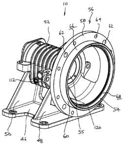
to provide a better view of the elements of the base 10. As shown in Figure 3,
the pedestal
or base 10 comprises a baseplate 46 having spaced apart legs 48, 50 that
support a main
body 52. The main body 52 includes a bearing assembly mounting portion for
receiving at
least one bearing assembly for the pump drive shaft 42, which extends
therethrough. The
main body 52 has a series of bores 55 extending therethough to receive the
drive shaft 42.
At one end 54 of the main body 52 there is formed a pump housing mounting
member for
mounting and securing the pump housing 20 thereto. The mounting member is
illustrated
as having a ring-shaped body portion 56 that is integrally formed or cast.with
the main
body 52 so that the pump housing support is an integral, one-piece, component.
However,
in other embodiments the ring-shaped body and main body may be separately
formed or
cast or secured together by any suitable means.
The ring-shaped body 56 comprises a radially-extending mounting flange 58 and
an
axially-extending, annular locating collar (or spigot) 60 extending therefrom,
the mounting
flange 58 and the spigot 60 serving to locate and secure various elements of
the pump
housing 20 to the pedestal or base 10, as is described more fully below. While
the
mounting flange 58 and annular locating collar or spigot 60 are shown in the
drawings as
continuous ring-like members, in other embodiments the mounting member need
not
always include. a ring-shaped body 56 in the form of a continuous, solid ring
which is
attached to, or formed integrally with the main body 52, and in fact the
flange 58 and/or
the spigot 60 may be formed in a broken or non-continuous ring form.
The pedestal 10 inclu' des four apertures 62 that are formed through the
mounting
flange 58, and spaced thereabout, for receiving liner locating and fixing pins
63 for
locating the main liner or volute 34 and the pump outer casing 22 relative to
one another.
There are four of these apertures 62 arranged circumferentially around the
ring-shaped
body 56 and positioned in between the plurality of screw-receiving apertures
64 which are
also positioned through the mounting flange 58. The screw-receiving apertures
64 are
arranged for receipt of securing members for securing the side casing part 24
of the pump
.casing 22 to the mounting flange 58 of the pedestal 10. The screw receiving
apertures 64
co-operate with threaded apertures located in the side casing part 24 of the
pump.casing 22
to receive mounting screws.
Amended Sheet
IPEA/AU
CA 02727536 2010-12-10
WRPofMDC[\STAU.20773_J DOC.,AN/2010 PCT/AU2009/000742
Received 7 April 2010
_12-
The annular locating collar or spigot 60 is formed with a.second locating
surface 66
corresponding to the outer. circumference of the annular locating collar 60
and a first
locating surface 68 corresponding to the inner circumference of the annular
locating collar
60, facing inwardly towards the shaft 42 rotation axis. These respective inner
and outer
locating surfaces 66, 68 are parallel to one another and parallel to the
rotation axis of the
drive shaft 42. This feature is best seen in Figure 16. Referring to Figures
16 and 17 a part
of the main liner 34 abuts against the outer locating surface 66, and parts of
the side liner
36 and stuffing box 70 abut against the inner locating surface 68 when the
pump 8 is in an
assembled position. The locating surfaces 66 and 68 can be machined at the
same time as
the bore 55 which extends through the main body 52 is machined, with the part
set-up in
the machine in one set-up operation. Such a technique to finish the
manufacturing of the
product can ensure true parallel surfaces 66, 68 and alignment with the bore
55 for the
drive shaft.
Reference is made to Figures 16 and 17 which illustrates how the pump.
pedestal 10
functions to align and attach various elements of the pump and the pump
housing 20 to the
pump pedestal 10 during assembly of the pump. The pump housing 20 shown in
Figure 16
comprises two side casings 24,26 as previously described. The two side casings
24, 26 are
joined about their peripheries and are secured with a plurality of securement
devices, such
as bolts 46. The side casing part 26 is on the suction side of the pump 8 and
is provided
with the inlet hole 28. The side casing part 24 is on. the drive (or motor)
side of the pump 8
and is securely attached to the mounting flange 58 -of the pump housing
support 10 by
screws or threaded mounting bolts positioned through the screw-receiving or
threaded
apertures 64 formed in the mounting flange 58.
The pump casing 22 is provided with an inner main liner 34, which may be a
single
piece (typical of metal. liners) -as shown in Figures 3 and 16 or two pieces
(typical of
elastomer liners). The inner main liner 34 further defines a pump chamber 72
in which the
impeller 40 is positioned for rotation. The impeller 40 is attached to a drive
shaft 42 that
extends through the pedestal or base 10 and is supported by a first bearing
assembly 75 and .
a second bearing assembly 77 housed within the first annular space 73 and
second annular
space 79, respectively, of the pedestal 10.
Amended Sheet
IPEA/AU
CA 02727536 2010-12-10
PCT/AU2009/000742
C WRPmW'DCCW,%\2245753 I.DM-I M4nO10
Received 7 April 2010
-13-
The stuffing box 70 is shown in Figures 23 to 28 and is positioned about the
drive
shaft 42, and provides a shaft seal assembly about the drive shaft 42. The
inner main liner
34, stuffing box 70, and casing side liner 36 are all properly aligned by
contact with one of
the locating surfaces 66, 68 of the annular locating collar or spigot 60, as
best illustrated in
Figure 17.
Figures 16A and 17 depict an enlarged section of the pump assembly shown in
Figure 16. In particular, a portion of the mounting member 56 of the pump
pedestal or
base 10 is illustrated depicting attachment of elements of the pump. As shown,
the side
casing part 24 is formed with an axially extending annular flange 74 that' is
sized in
diameter to fit about the second, outward-facing locating surface 66 of the
annular locating
collar or spigot 60 of the pump pedestal 10. The annular flange 74 of the side
casing part
24 also registers against the mounting flange 58 and is structured with
apertures 76 which
are positioned to align with the bores 64 in the mounting flange 58 of the
pump base 10.
The annular flange. 74 of the side casing part 24 is also formed with bores
that align with
the apertures 62 of the=,:mounting flange 58 for positioning securement
devices
therethrough as previously described.
The stuffing box 70 has a radially-extending portion 78 that registers against
an
inner shoulder 80 of the locating collar or spigot 60 of the pedestal 10 and
against the first
locating surface 68 of the spigot 60. The casing side liner (or back liner) 36
is also
structured with a radially-extending portion 82 that is positioned adjacent
the extending
portion 78 of the stuffing box 70 and registers against the first locating
surface 68 of the
collar or spigot 60. The inner main liner 34 has a radially-inwardly extending
annular
portion 84 that registers against the extending, portion 82 of the casing side
liner 36 and is
aligned in place accordingly. = Thus a portion : of the casing side liner 36
is disposed
between the stuffing box 70 and the inner main liner 34. In the case of metal
parts, gaskets
or o-rings 86 are used to seal the spaces between the respective parts.
The inner main liner 34 is configured with an axially-extending annular flange
or
follower 88 that is sized in diameter to be received about the outer
circumference or second
locating surface 66 of the annular locating collar or flange 60. The annular
follower 88 is
also sized in circumference to be received within an annular space 90 formed
in the
annular flange 74 of the side casing part 24. The follower 88 is formed with a
radially-
Amended Sheet
}PEA/AU
CA 02727536 2010-12-10
PCT/AU2009/000742
C srmra1e1\occssrAa:45755_1 ooc=imu:mo
Received 7 April 2010
-14-
extending lip 92 that has a face 94 that is oriented away from the mounting
flange 58 of the
pump base 10. The face 94 of the lip 92 is angled from a plane that is
perpendicular to the
rotational axis of the pump 8.
A liner locating and fixing pin 63 is received through the bore 62 in the
mounting
flange 58 and into the aperture 96 of the side casing part 24 to engage the
lip 92 of the
inner main liner 34. A head 98 of the fixing pin 63 may be configured to
engage the lip 92
of the follower 88. The head 98 of the fixing pin 63 may also be formed with a
configured
terminal end 168 locating section that seats against the side casing part 24
in a blind end
cavity 100 such that rotation of the fixing pin 63 exerts a thrust force that
provides
movement of the inner main liner 34 relative to the side casing part 24 and
locks the fixing
pin 63 in place.
The arrangement of the pump pedestal 10 and the pump elements is such that
mounting member 56 and its associated mounting flange 58 and annular locating
collar or
flange 60, having the first locating surface 68 and second locating surface
66, provide for
proper alignment of the pump casing part 24, inner main liner 34, casing side
liner 36 and
stuffing box 70. The arrangement also properly aligns the drive. shaft 42 and
impeller 40
relative to the pump housing 20. These interfitting parts become properly
concentrically
aligned when at least one of the components is in contact with a respective
one of the first
locating surface 68 and the- second locating surface 66. For example, of
primary
importance is the alignment of the annular -follower 88 of the inner main
liner 34 with the
second locating surface 66 (to position the main liner in concentric alignment
in relation to
the. pedestal 10), as well as the alignment of the stuffing box 70 with the
first locating
surface. 68 (to provide good concentric alignment of the stuffing box bore
with the shaft
42). Many of the alignment advantages of the pump apparatus can be achieved if
these
two components are located at the respective locating surfaces of the spigot
or collar 60.
In other embodiments if there is at least one component positioned on either
side of the
annular locating collar or flange 60, then it is envisaged that other shapes
and arrangements
of components parts can be developed to interfit with one another and maintain
the
advantages of concentricity offered by the arrangement shown in the embodiment
shown
in the drawings.
Amended Sheet
IPEA/AU
CA 02727536 2010-12-10
C WRPO ibMCC\S7A12i 755_I.DOC-1RN/2010 PCT/AU2009/000742
Received 7 April 2010
-15-
The use of the annular locating collar or flange 60 allows the pump casing 22
and
casing side liner 36 to be aligned accurately with the stuffing box 70 and the
drive shaft 42.
Consequently, the impeller 40 can rotate accurately within the pump chamber 72
and the
inner main liner 34 to thereby allow, much closer operating tolerances between
the interior
of the inner main liner 34 and the impeller 40, especially at the front side
of the pump 8 as
will shortly be described.
Furthermore, the arrangement is an improvement on conventional pump housing
arrangements because both the stuffing box 70 and the pump liner 34 are
positioned
relative to the pump pedestal 10 directly, thus improving the concentricity of
the pump in
operation. In prior art arrangements, the shaft turns in a shaft housing which
is itself
attached to a pump housing support. The pump housing support is associated
with the
casing of the pump. Finally, the stuffing box is linked to the pump casing.
Therefore the
link between the shaft housing and the stuffing box in prior art arrangements
is indirect,
leading to a stacking of tolerances which often is a source of problems such
as leakage,
necessitating the use of complicated packing, and so on.
In summary, without limitation the embodiment of the pump base or pedestal 10
described herein has at least the following advantages:
1. a. single spigot to attach and align both the pump casing, pump liners and
the stuffing box to the pump shaft axis without relying on the alignment of
these through a
number of.associated parts, which invariably cause misalignment due to the
normal stack-
up of tolerances.
2. a spigot which can be machined in the same operation with the part set-up
in the machine in the one operation as the bore for the shaft, and so has true
parallel outer
and inner diameters.
3. a unitary (one piece) pump pedestal or base, which is easier to cast and
then
machine finish.
4. a pump with overall improved concentricity - if a metal liner is used, it
in
turn aligns the pump front entry liner 38 (sometimes referred to as the
throatbush) to the
pump shaft. That is, the shaft 42 is aligned concentrically with the pedestal
10 and with
the flange 58 and spigot 60, which in turn means that the casing 24 and the
main liner 34
are aligned directly with.the shaft 42, which in turn means that the front
casing 28 and the
Amended Sheet
IPEA/\U
CA 02727536 2010-12-10.
PCT/AU2009/000742
C 1NRPor1bODCCISTAV,2457 33_I DOC=IRNl2010
Received 7 April 2010
-16-
main liner 34 are aligned with the shaft 42, so that the front liner 38 and
shaft 42 (and
impeller 40) are in better alignment. As a result, the gap between the pump
impeller 40
and the front liner 38 at the inlet of the pump can-therefore be maintained
concentric and
parallel - that is, the front side liner inner wall is parallel to.the front
rotating face of the
impeller, which results in improved pump performance and reduced incidence of
erosive
wear. The improvement in concentricity therefore extends across the whole
pump.
5. In the arrangement shown, the shaft 42 is fixed in position (i.e., to
prevent
sliding toward or away from the pump housing 20). The slurry pump industry
standard
conventionally provides a shaft position that is slidingly adjustable in an
axial direction to
adjust the pump clearance (between the impeller and front liner), however this
method
increases the number of parts, and the impeller cannot be adjusted while the
pump is
operating. Also, in industry practice, adjusting the shaft position affects
the drive
alignment which should also be realigned, but is seldom realigned because of
the extra
maintenance time required to make the adjustments. The configuration shown
herein
provides a non-sliding shaft, offers- fewer parts and less maintenance.
Further, the bearings
used can take thrust in either direction depending on the pump application,
and no special
thrust bearing is required.
During assembly of a pump for the first time, the stuffing box 70 and then the
casing side liner 36 are positioned on the first locating surface 68 and in
contact with one
another, and fitting of the outer casing 24 by screwing to the mounting flange
58 can occur
before, in between, or after those two steps. Thereafter the main liner 34 can
be positioned
by sliding along the second locating surface 66 towards the,pedestal 10 until
the extending
annular. portion 84 of the inner main liner (which is arranged beyond the free
end of the
annual locating collar 60) registers against the extending portion 82 of the
casing side liner
36 and is aligned in place accordingly, so that the casing side liner 36 is
located in close
interfitting relation between the stuffing box 70 and the inner main liner 34.
This same
procedure can be followed in reverse during maintenance or retrofitting of.
new pump
components onto the pedestal or base 10.
Referring to Figures 6 to 15, the details of the features of the pump pedestal
or base
10 will now be described. Figures 6 to 15 illustrate the pump pedestal or base
10 with the
pump housing 20 removed to provide a better view of the elements of the base
10. As
Amended Sheet
fPEAIAU
CA 02727536 2010-12-10
PCT/AU2009/000742
C UfRPp1b11DCClSTAU241715_I DM-I/O,RO10
Received 7 April 2010
-17-
already described in relation to Figure 3, the pedestal or base 10 comprises a
main body 52
which includes a bearing assembly mounting portion for receiving at least one
bearing
assembly for the pump drive shaft 42, which extends therethrough. The main
body 52 has
a series of bores or openings 55, 102 extending therethough to receive the
drive shaft 42.
As best seen in Figure 12, the main body 52 of the pump pedestal or base 10 is
hollow, having a first opening 55 oriented toward the first end 54 of the pump
base 10 and
a second opening 102 at the second end 103 of the pump base 10. A rear flange
122 is
provided at the second end 103. The rear flange 122 provides means for
attaching an end
cap of a bearing assembly 124 as shown in Figure 5, as is known in the art. A
barrel-like
chamber 104 having a generally . cylindrical interior wall 116 is formed
between the first
opening 55 and second opening 102. The drive shaft (not shown) of the pump 8
extends
through the second opening 102, through the chamber 104 and through the first
opening 55
as described further below. A first annular space 73 is formed in the main
body 52 toward
the first end 54 of pump base 10;. and a second annular space 79 is formed
toward the
second end 102 of the pump base 10. The first annular space 73 and second
annular space
79 are structured as receiving zones to each receive a respective ball or
roller bearing
assembly therein (first bearing assembly 75 and a second bearing assembly 77
shown in
Figure 5) housed therein and through which the drive shaft extends. The
bearing
assemblies 75, 77 carry the drive shaft 42.
The chamber 104 of the main body 52 is arranged to provide a retainer for a
lubricant to lubricate the bearing assemblies 75,=77. A sump 106 is provided
at the bottom,
of the chamber 104. As best seen in Figures 12 and 13, the main body 52 may be
formed
with a venting port 108 through which a lubricant may be introduced into the
chamber 104,
or through which pressure in the chamber 104 may be vented. The main body 52
may also
= be structured with a drain port 110 for draining lubricant from the main
body 52. Further,
the main body 52 may be structured with a window 112 or similar device for
checking or
determining the level of lubricant in the chamber 104.
The pump pedestal or - base 10 may be adapted to retain different types of
lubricants. That is, the chamber 104 and the sump 106 may accommodate the use
of fluid
lubricants, such as oil. Alternatively, more viscous lubricants such as grease
may be used
to lubricate the bearings and, to that end, lubricant retaining devices 114
may be positioned
Amended Sheet
IPEA/AU
CA 02727536 2010-12-10
C NRPWbl\DCC\STA13245755 I DOC.IM1WROIO PCT/AU2009/000742
Received 7 April 2010
-18-
within the main body 52, adjacent the first annular space 73 and second
annular space 79
to assure proper contact between a more viscous lubricant and the bearing
assemblies 75,
77 housed within the respective annular spaces. 73, 79 by forming a partial
barrier between
the bearing assemblies 75, 77.located in the respective annular spaces 73, 79
and the sump
106, as will now be described..
The first annular space 73 is demarcated from the chamber 104 by a first wall
shoulder portion '118 that extends from the interior wall 116 toward the axial
centreline of
the base or pump pedestal 10. The second annular space .79 is demarcated from
the
chamber 104 by a second wall shoulder portion 120 that also extends from the
interior
wall 116 toward the centreline of the base or pump pedestal 10.
Each lubricant retaining device comprises an annular barrier wall in the form
of a
ring portion 126, as best shown in Figures 14 and 15, that has an outer
circumferential
edge 128. As shown in Figure 13, the outer circumferential edge. 128 of the
lubricant
retaining device 114 is sized to be received within a groove 130, 132 formed,
respectively,
in the first wall portion 118 and second wall portion 120. The lubricant
retaining device
114 is made of a material that imparts substantial stiffness to the ring
portion 126. In a
particularly suitable embodiment, the lubricant retaining device 114 is made
of a.material
that while sufficiently rigid,'lias a sufficient modulus of elasticity to
render=the ring portion
126 sufficiently flexible so that the circumferential edge 128 can be eased
into and out of
position within the groove 130, 132.
Each lubricant retaining device 114 is also formed with a basal flange 134
which
extends laterally from the ring portion 126 and which, as best illustrated in
Figures 12 and.
13, when in use is sized to extend over (or overlie) a respective first
channel 136 and
second channel 138 adjacent the sump 106 to regulate the movement of lubricant
out of a
first drain slot 140 (in the base of the first anular space 73) and out of a
second drain slot
142 (in the base of the second annular space 79) leading into the sump 106. In
use a free
outer edge of the basal flange 134 abuts a respective bearing assemblies 75,
77.
In operation it is desirable that a relatively more highly viscous lubricant
material
such as grease is maintained in circulation in the. area of the bearing
assemblies 75, 77 and
does not collect in the sump 106 of the base or pedestal 1Ø Lubricant that
is in contact
with the bearing assembly 75--housed within the first annular space 73
normally travels, by
Amended Sheet
IPEA/AU
CA 02727536 2010-12-10
PCT/AU2009/000742
C wRVa+bnoccSrMzzesrss_i 00c=11114oi0
Received 7 April 2010
-19-
gravity, toward the first drain slot 140 and then travels into a first channel
136 that is in
fluid communication with the sump 106. Likewise, lubricant that is in contact
with the
bearing assembly housed within the second annular space 79 normally travels,
by gravity,
towards the second drain slot 142 and then travels into a second channel 138
that is.in
5. fluid communication with the sump 106. When in position the lubricant
retaining devices
114 are designed to retain lubricant in contact with the respective bearing
assemblies 75,
77 in the first and second annular spaces 73, 79. That is, the ring portion
126 . of the
lubricant retaining devices 114'acts to retain grease in contact with the
bearing assembly so
that the grease is not displaced into the sump 106. The basal flange 134
restricts the flow
of fluid entering into the first 136 or second 138 channels. Consequently, the
bearings are
properly lubricated by assuring sufficient contact time and retention between
the bearing
assembly and the grease (or grease-like substance).
Alternatively, if a flowable fluid, such as oil, is used as the lubricant, the
lubricant
retaining devices 114 are removed entirely to allow a flowable fluid, such as
oil, to be used
as the lubricant for lubrication of the bearing assemblies 75, 77. This
enables oil or
another flowable lubricant to be in free contact with the bearing assemblies
75, 77, which
may be appropriate and desirable in certain applications.
The present arrangement of removable lubricant retainers 114 means that the
same
bearings can be lubricated either with grease or with oil: In order to achieve
this, because
the volume inside the frame is typically large and grease lubrication would be
too easily
lost from the bearings (which could lead to reduced bearing life), the snap-in
lubricant
retainers 114 (also known as grease retainers) are positioned to contain the
grease in close
proximity to the respective bearing assemblies 75, 77. Oil on the other hand,
requires
space to flow and to form a bath that will partially submerge a bearing in
use. In such
instances, the grease retainers 114 are not required at all and, if present,
could cause the oil
to bank up in the region of the bearing, thus causing excess churning and
heating. Both of
these conditions would reduce the bearing life.
Referring to the drawings, further details of the features of the pump inner
main
liner 34 and the details of the fixing pin 63 will now be described. Figures
18 to 22
illustrate the fixing pin 63, and Figures 16 and 17 illustrate the position of
the fixing pin 63
in use with the pump assembly. Figures 3, 16, 17, 55 and 56 illustrate the
pump main liner
Amended Sheet
[PEA/AU
CA 02727536 2010-12-10
C WRPO1b11DCCISTAU245755 I DOC=Ir04/2010 PCT/AU2009/000742
Received 7 April 20.10
-20-.
34. Figures 57 and 58 illustrate a perspective, exploded view of the pump
housing
showing two possible configurations of the positioning of the inner main liner
34 during
maintenance of the pump. .
As previously described, to locate the inner main liner 34 in relation to the
pedestal
10 as well as to the side casing part, 24, four separate locating and fixing
pins 63 are
provided. In other embodiments it is envisaged that more'or less than four
fixing pins 63
can be used. As shown in the drawings the. inner main liner 34 is positioned
within the
pump casing 22 and generally lines the central chamber of the. pump 8 in which
an
impeller 40 is positioned for rotation, as is known in the art. The inner main
liner 34 may
be made of a number of different 'materials that impart wear-resistance. An
especially
commonly used material is an elastomer material.
As has already been described, the annular follower 88 is formed with a
radially-
extending lip 92 that has a face 94 that is oriented away from the'mounting
flange 58 of the
pedestal 10. The face 94 of the lip 92 is angled from a plane that is
perpendicular to the
rotational axis of the pump 8. , As shown in Figure 17, a coupling and fixing
pin 63 is
positioned through the bore 62 in the mounting flange 58 of the pedestal 10
and into the
aperture 96 of the side casing part 24 to engage the lip 92 of the inner main
liner 34.
The structural configuration of the. fixing pin 63 is shown in Figures 18 to
22. The
fixing pin 63 includes a shank 144 having a head 98 at one end 148 and a tool
operable
element 150 at the other end 152. The shank 144. includes a neck section 154
and the head
98 includes a cammed surface 156 thereon. The caromed surface 156 includes a
leading
edge 158,-a first section 160 and a second section 162 which terminates at a
shoulder 164.
.The head 98 has a flat surface' section 166 adjacent the leading edge 158 of
the cammed
surface 156, and also adjoining the shoulder 164. As can be seen in the
drawings, the first
section 160 of the cammed surface 156 is of greater inclination compared to
the second
section 162. The cammed surface 156 is generally spirally, screwingly or
helically shaped
in a direction away from, the one end 148. The head 98 further. includes a
profiled locating
free end 168 at the other end 152'.
As shown in Figures 16 and 17 the fixing pin 63 is received within the
aperture or
opening 96 in the side casing part 24, the aperture 96 having a configured
terminal end (or
blind end) cavity 100 with a profiled section which co-operates with the
profiled free end -
Amended Sheet
IPEA/AU
CA 02727536 2010-12-10
C WRPmb1VDCC\STA\2245755 i in4l?I O PCT/AU2009/000742
Received 7 April 2010
-21-
or terminal end locating section 168 of the head 98 of the fixing pin 63. The
cammed
surface is adapted to engage against the follower 88 portion of the inner main
liner 34.
The follower 88 takes the form of an annular flange which extends axially from
the side of
the inner. main liner 34, and which comprises an annular circumferential
groove 170
defined by the radially extending lip 92, where the face 94 of the lip 92 is
angled from a
plane that is perpendicular to the rotational axis of the pump.
When deployed in use, the fixing pin 63 is inserted through the aperture 62 of
the
mounting flange 58, and the flat surface section 166 is dimensioned to allow
the head 98 to
pass over the outer rim of the radially extending lip 92 on the side of the
inner main liner
34 when the fixing pin 63 is in the correct orientation.' The fixing pin 63
has.a profiled
locating free end 168 which is conical in shape which corresponds to the
conical bottom of
the blind end 100 of the aperture 92. When the fixing pin 63 is inserted, its
terminal end
168 registers against and seats in the bottom of the blind end 100, and the
fixing pin 63 can
then be turned with a spanner or similar tool. The contact between the free
end 168 of the
fixing pin 63 and the blind end 100 assures proper positioning of the caromed
surface 156
relative to the lip 92 of the inner main liner 34, and provides. a locating
device for the
fixing pin 63.
As the fixing pin 63 is rotated, the helically-shape caromed surface 156
engages
with the outer end of the groove 170 on the side flange of the inner main
liner 34. Because
the groove 170 has a sloping inside face 94, as the fixing pin 63 is rotated,
the. helically-
shape caromed surface .156 commences to make contact on, and bear against, the
inner
main liner 34 causing movement relative to the side casing part 24 (to draw
the inner main
liner .34 closer toward the side casing part 24 in an axial displacement). The
resulting
thrust also forces the end of the fixing pin 63 into contact with the bottom
of the blind end
100 in the aperture 92 of the pump casing-part 24 and to rotate. Consequently
the fixing
pin 63 becomes locked in place as the shoulder 164 of the head 98 contacts the
lip 92 to
stop its rotation. The groove=170 and the head end 98 of the fixing pin 63 are
dimensioned
such that the. fixing pin 63 locks, after only around 180 degrees of rotation.
The slower
pitch on the end portion 162 of the caromed surface 156 assists with locking
the fixing pin
30, 63, and also prevents loosening. .
The fixing pin 63 is self-locking and does not loosen. until released by
counter-
Amended Sheet
IPEA/AU
CA 02727536 2010-12-10
C:\NRPonb1\DCCISTA\2213735 I DOC=IrtX2010 PCT/AU2009/000742
Received 7 April 2010
-22-
rotation of the fixing pin 63 by use of a tool. For the purpose of rotation of
the fixing pin .
63, the *tool-receiving end 66 may be configured to receive a tool, and as
illustrated, the
tool-receiving end 66 may be formed as a hex-head to receive a spanner or
wrench. The
tool receiving end 66 may be configured with any' other suitable shape,
dimension or
device for receiving a tool that can rotate the fixing pin 63.
A plurality of apertures or openings.62 are formed about the mounting flange
58 of
the pedestal 10, and a plurality of apertures 96 are formed in the pump side
casing part 24
I,I\ .
to accommodate a plurality of fixing pins 63 being position therethrough to
secure the
inner main. liner 34 in place as described. While the fixing pin 63 is
described and
illustrated herein with respect to securing the inner main liner 34 on the
drive side of the
pump casing part 24, the fixing pin 63 and cooperating elements are also
adapted to secure
the opposite side of the inner main liner 34 to the.pump casing part 26, as
shown in Figures
16, 16C and 58. This is because the liner 34' has a similar follower 88 and
groove 170
arrangement on its opposing side, as will now be described.
The inner main liner '34~sho'vn in Figure 3 is arranged with openings 31 and
32 in
opposed sides thereof, one of which 31 provides for an inlet opening for the
introduction of
a flow of material into the main pumping chamber 34. The other opening 32
provides for
the introduction of the drive shaft 42 used for rotatably driving the impeller
40 which is
disposed within the inner main liner 34. The inner main liner 34 is of volute
shape with a
discharge outlet hole 30 and a main body that is shaped generally like a car
tyre.
Each of the side openings 31 and 32 of the main liner 34 are surrounded by
like,
continuous, circumferential, outwardly projecting flanges which each have a
radially
extending lip 92 and a groove 170 defined by the lip 92. The grooves 170 have
an inclined
side face 94 which can act as a follower 88 and the inclined side face is
adapted to
.25 cooperate. with a fixing pin 63 as illustrated in Figure 17, used to fit
the main liner 34 to
another component of the pump assembly. It is the angled face 94 of the lip 92
which
allows engagement of the inner main liner 34 to other components.
Figures 57 and 58 illustrate a perspective, exploded view of the pump housing
showing two possible configurations of securing the inner main liner 34 during
maintenance of the pump. The continuous, circumferential, outwardly projecting
flanges
which each have a radially extending lip 92 and a groove 170 are shown on both
sides of
Amended Sheet
[PEA/AU
CA 02727536 2010-12-10
PCT/AU2009/000742
c.wWonnnncc%S7M2:45753i.ooc.imaaoio
Received 7 April 2010
-23-
the volute liner 34 - in Figure 57 the volute liner 34 is held by fixing pins
63 to the casing
side part 24 (frame plate), and in Figure 58 the volute liner 34 is held by
fixing pins 63 to
the casing side part 26 (cover plate). In both cases it is the engagement of
the fixing pin 63
with the radially extending lip 92 which permits these configurations, with
the advantage
during maintenance of being able to access the front liner 38 as shown in
Figure 57 and
being able to freely access the impeller 40 and the back liner 36 in the
configuration shown
in Figure 58, without the need to disassemble the whole pump. The volute liner
34. can be
easily released and removed from one of the side parts 24, 26, and held or
retained on one
or the other of the respective side parts 24, 26
As shown in Figures 3, 50, 51, 52 and 57 there is a further peripheral groove
172
which extends. around the inner circumferential surface of the outwardly
projecting volute
side flanges, on the side of the flanges opposite to the side having the lip
92 and groove
170. This groove 172 is adapted to receive a seal therein as illustrated in
the Figures and
as described herein.
Referring to the drawings, further details of the features of the pump seal
chamber
housing will now be described. In one form of this, Figures 23 to 34
illustrate the stuffing
box 70 which is positioned in use about the drive shaft 42, and provides a
shaft seal
assembly about the drive shaft 42. The stuffing box is also shown in Figure 3.-
Figure 23 illustrates"a seal assembly which comprises a stuffing box 70 having
a
central section 174 and generally radially extending wall section 176. The
wall section
176 has a first side 178, which is generally oriented toward the pumping
chamber. of the
pump when the pump is assembled, and a second side 180, which is generally
oriented
toward the drive side of the pump when the pump is assembled.
A centralised bore 182 extends through the central section 174 of the,
stuffing box
70 and-has an axially-extending inner surface 184 (also shown in Figure 24).
The bore 182
is adapted to receive a drive shaft 42 therethrough. A shaft sleeve 186 may
optionally be
positioned about the drive shaft 42, as shown in Figures 1 and 2.
An annular space 188 is provided between the outer surface 190 of the shaft
sleeve
186 and the inner surface 184 of the bore 182. The annular space 188 is
adapted to receive
packing. material, shown here as packing rings 192 as just one exemplar
packing material.
A lantern ring 194 is also positioned in the annular space 188. At least one
fluid channel
Amended Sheet
IPEA/AU
CA 02727536 2010-12-10
C.W"-W\DCCWAU2457551.DOC-i,oamIo PCT/AU2009/000742
Received 7 April 2010
-24-
196 is formed in the stuffing box 70, having an external opening 198
positioned near the
central section 174, as best illustrated in Figures 25 and 26, and an internal
opening 200
which terminates in alignment with the lantern ring 194. This arrangement
facilitates the
injection of water via the fluid channel 196 into the region of the packing
rings 192.
Figure 23 depicts a first embodiment of the stuffing box 70 wherein the
lantern ring
194 is positioned toward the one end of the annular space = 188. Figure 24
depicts a second
embodiment of the seal housing wherein the lantern ring 194 is positioned
inbetween the
packing rings 192. This arrangement may provide fluid flushing capabilities
that are more
suitable to some applications.
A packing gland 202 is disposed at the outer end of the bore 182 and is
adapted to
contact the packing material 192 to compress the packing material within the
annular space
188. The packing gland 202 is secured in place relative to the annular space
188 and
packing material 192 by adjustable bolts 204 that engage the packing gland 202
and attach
to saddle brackets 206 that are formed on the central section 174 of the
stuffing box 70, as
best seen in Figures 25 and 26. , 'The axial position of the packing gland 202
is selectively
adjustable by adjustment of the bolts 204.
The. stuffing box 70 is configured with means for lifting and transporting it
into
position about the drive shaft 42 when the pump 8 is being assembled or
disassembled.
The stuffing box 70 is structured with a holding member 208 that encircles the
centralised
bore 182, as shown in Figures 27 and. 28. The holding member 208 is generally
a ring
formation 210 that may either be integrally formed with the stuffing box 70,
such as by
casting or molding, or may be a separate piece that is secured to the stuffing
box 70 in any
suitable manner about the centralised bore 182.
As shown in Figure 23, the ring formation 210 is configured with an outwardly
extending and angled lip that flares away from the bore 182. The lip provides
a bearing
surface 212 or inclined bearing face against which a lifting element may be
positioned for
grasping the stuffing box 70, as explained more fully below. The lip extends
outwardly
from an axially-extending wall 214 of the bore 182. The wall 214 forms an
annulus 216
the diameter of which is sized to contact the drive shaft 42 or shaft sleeve
186, as depicted
in Figure 23.
It is further noted in Figures 23 and 24 that a radially-extending shoulder
218 is
Amended Sheet =
IPEA/AU
CA 02727536 2010-12-10
Wo,,PI)CC\STA,2245755_1,o .,A)412010 PCT/AU2009/000742
Received 7 April 20,10
-25-
located adjacent the axially-extending wall 214 and forms an inward end of the
annular
space 188. The shoulder 218 and wall 214 form a restrictor or throttling bush
220 for the
annular space 188 such that fluid introduced into the annular space 188 via
the fluid
channel 196 and lantern ring 194 is restricted from entering into the pumping
chamber.
Because of the improved concentricity of the pump components brought about by
the
various interfitting arrangements already described to reduce the incidence of
tolerance
stacking, the throttling bush 220 is able to be positioned in a close-facing
relationship with
the exterior of the drive shaft 42 or shaft sleeve 186, to restrict the water
entering into the
pumping chamber.
It is envisaged that the same type of holding member that encircles the
centralised
bore in a general ring formation can also be applied to other forms of seal
housing, for
example in an expeller ring, and can also be applied to facilitate the lifting
and movement
of the back liner 36.
Figures 29 to 34 illustrate a lifting device 222 that is designed for
attaching to the
-seal assembly by means of the holding member 208 formation, for lifting,
transporting and
aligning the seal assembly. The lifting device 222 comprises two angle beams
224 that are
secured together in spaced apart arrangement forming an elongated main body
portion 226
of the lifting device 222. A first mounting arm 228 and second mounting arm
230 are
secured to the main body 226 and provide a means by which the lifting device
222 may be
attached to a:-crane or other suitable apparatus for facilitating movement and
positioning
thereof. The two angle beams 224 may, most suitably, be secured to the
mounting arms
228, 230, by such means as welding, bolts, rivets or other suitable means.
Three clamping arms or jaws 232,234, 236 are operatively mounted to and extend
outwardly from the main body 226. The lowermost clamping jaws 234 and 236 are
fixedly
secured to respective angle beams 224 of the main body 226, as shown in Figure
31, and
the uppermost clamping jaw 232 is adjustable relative- to the longitudinal
length of the
main.body 226. Adjustment of the clamping jaw 232 is accomplished by an
adjusting
apparatus 238 on the lifting device 222 that comprises a stationary bracket
240 secured to
the main body 226 by bolts 242, and a slidable bracket 244 that is positioned
between the
two angle beams 224 and is movable =therebetween. The slidable bracket 244 is
connected
to the-stationary bracket 240 by a threaded rod 246 that extends through both
'the slidable
Amended Sheet
IPEA/AU
CA 02727536 2010-12-10
C UJRPOr101\DCCVSTAU.215755 1 DOC-IAM/201n PCT/AU2009/000742
Received 7 April 2010
-26-
bracket 244 and the stationary bracket 240 as shown in Figures 29 and 30. The
slidable.
bracket 244 is moved relative to the stationary bracket 240 by turning nuts
248 and 250 in
an appropriate direction to. effect movement of the slidable bracket 244, and
hence the
clamping jaw 232.
It can be seen from Figures 29, 32 and 34 that each of the clamping jaws 232,
234,
236 is structured with a hook-like end 252 that is configured to engage the
lip of the ring
formation 210 of the holding member 208 on the seal housing. Notably, Figures
32 to 34
show only the clamping jaws 232, 234, 236 in position relative to the holding-
member 208,
the other components of the lifting device 222 having been removed for ease of
viewing
and explanation. In particular, it can be seen that the hook-like end 252 of
each clamping
member 232, 234, 236 is structured to contact the bearing surface 212 of the
lip.
It can further be seen from Figures 29, 32 and 33 that the clamping jaws 232,
234
and 236 are generally arranged to engage the holding member 208 at three
points about the
circumference of the holding member 208 to assure stable securement by the
lifting device
222. The stuffing box 70 is secured to the lifting device 222 by first moving
clamping arm
232, by operation of slidable bracket 244, to be spaced apart from the other
two clamping
jaws 234 and 236. The holding member 208 is then engaged by the hook-like ends
of
clamping jaws 234 and 236. While maintaining the stuffing box' 70 in parallel
alignment
with the main body 226 of the lifting device 222, the clamping jaw 232 is
slidably moved
by operation of slidable bracket 244 to effect engagement of its hook-like end
with the lip
of the holding member 208. The secure engagement of the holding member 208 by
the
clamping jaws 232, 234, 236 is assured by tightening the nuts 248, 250. The
stuffing box
70 can then be moved into position about a drive shaft 42 and secured in place
relative to,
the other components of the pump casing 22 as is known in the art.
Disengagement of the
lifting device 222 from the holding member 208 is effected by reversing.the
recited steps..
Referring to the drawings, further features of the pump outer casing 22 will
now be
described. In one form of this, Figures 35 to 39 and 40A and 40B illustrate a
pump
housing 20 generally comprising ah outer casing 22 that is formed from two
side casing
parts or halves 24, 26 (sometirhes also known as the frame plate and the cover
plate) which
are joined together about the periphery of the two side casings parts 24, 26.
As previously mentioned in relation to Figures 1 and 2, the two side casing
parts
Amended Sheet
IPEA/AU
CA 02727536 2010-12-10
C W"~bOCCSTA 2z4s'ss_$. .I )4/ O10 PCT/AU2009/000742
Received 7 April 2010
-27-
24, 26 of the outer casing 22 are joined together by bolts 46 located about
the periphery of
the casing parts 24, 26 when the pump is assembled for use. In addition, and
as shown in
Figures 36 to 40A and 40B, the two side casing halves 24, 26 are spigoted
together with a
tongue and groove joint arrangement so that, when assembled, the two casing
halves 24, 26
are concentrically aligned.
The first.side casing .24 is configured with an outer peripheral edge 254
having a
radial face 256, and the second side casing 26 is also configured with an
outer peripheral
edge 258 having a radial face 260. When the first side casing 24 and second
side casing 26
are joined, the respective peripheral edges 254, 258 are brought into-
proximity and the
respective faces 256, 258 are brought into registration and abutment.
As shown in Figures 35 to 38, each of the side casings 24, 26 is formed about
the
peripheral edge 254, 258 with a plurality of bosses 262 that extend radially
outwardly from
the peripheral edge 254,258 of the respective side casing 24, 26. Each of the
bosses 262 is
formed with an aperture 264 through which a bolt 46 is positioned in use, to
securely hold
the two side casings 24, 26 together in assembly of the pump casing 22, as
depicted in
Figure 35. An enlarged view of cooperating joined bosses is shown in Figure
39, with the
bolt 46 removed from. the aperture 264.
The side casings 24, 26 are further structured with locating apparatus 266, as
best
seen in Figures 37 and 38., The locating apparatus 266 are generally located
in proximity
to the peripheral edge 254, 258 of each side casing 24, 26. The locating
apparatus 266
may, in a particularly suitable embodiment, be positioned at the bosses 262 to
facilitate
alignment of the two side casings 24, 26 and to ensure that the side casings
24, 26 do not
move radially relative to each other whilst being connected together during
assembly or
disassembly of the pump casing 22.
The locating apparatus 266 may comprise any form, design,. configuration or
element that limits radial movement of the two side casings 24, 26 relative to
each other.
By. way of example, and in a particularly suitable embodiment as shown, the
locating
apparatus 266 comprise a plurality of alignment members 268 that are
positioned at several
of the bosses 262, in proximity to the aperture 264 of that boss 262. Each
boss 262 may be
provided with an alignment iinembei 268, or, as illustrated, less than all of
the bosses may
have an alignment member 268= associated therewith.
Amended Sheet
IPEA/AU
CA 02727536 2010-12-10
C WRVa1d'DCMTAU245755 1.000-IAMfin10 PCT/AU2009/000742
Received 7 April 2010
-28-
Each alignment member 268 is configured with a contact edge 270 that is
oriented
in general- parallel alignment with the circumference 272 of the peripheral
edge 254, 258
such that when the contact edge 270 of cooperating alignment members 268 are
registered
together at assembly of the pump casing, the two side casings 24, 26 cannot
move in a
radial plane relative to each other (that is, in a plane perpendicular to the
central axis 35-35
of the pump casing 10, shown in Figure 35). It should be noted that the
contact edges 270
may be linear. as shown, or may have a curvature of selected radius.
As best seen in Figures 40A and 40B, in one exemplary embodiment, the
alignment
members 268 may be configured as a projecting land 274 that extends axially
outwardly
from the radial face 256 of the peripheral edge 254. The projecting land 274
is structured
with a contact edge 270 that is oriented toward the central axis of the pump
casing 22. The
projecting. land 274 is depicted as being formed on the frame plate casing 24
in Figure
40A. A projecting ridge 276 that. extends axially outwardly from the radial
face 254 of the
cover plate casing 26 is shown in Figure 40B and is structured with a contact
edge 270 that
is oriented away from the central axis of the pump. This contact edge 270
registers against
the contact edge 270 of the projecting land 274 on the frame plate casing 24
when the two
side casings 24, 26 are brought together 'at assembly. Notably, the projecting
lands 274
and projecting ridges 276 may be located on either of the two side casings and
are not
limited to being located on the first side casing 24 and second side casing 26
as depicted.
It can further be seen from Figures- 36 and 37 that the shape, size, dimension
and
orientation of each of the projecting lands'274 located on the first side
casing 24 may vary.
That is, some of the projecting lands 274 may generally be formed as
triangulate forms
while other of the projecting lands 274 may be formed as- elongated rectangles
of
projecting material. The variation in the shape, size, dimension and
orientation.of each of
the projecting lands 274 is dictated by the machining process that forms the
projecting
lands 274. Because of the volute shape of the pump side casings, the machine
cutting
operation (having its centre of 'radius at the central axis. of the pump
housing) cuts a
circular groove which forms projections at some of the bosses, the projections
being of a
different shape from one another because of the manner of manufacture. The
variations
between the shapes of the projecting lands 274 can facilitates proper
alignment of the two
side casings 24, 26 at assembly and assures delimited movement relative to
each other.
Amended Sheet
[PEA/AU
CA 02727536 2010-12-10
PCT/AU2009/000742
C XNUMMO TA,:2457351 DO`_Irt no1` Received 7 April 2010
-29-
The provision of the co-operating projections and recesses allows for ready
alignment of the two side casings 24, 26 and of the mounting apertures 264
which receive
the bolts 46. This simplifies the assembly of the pump casing 22. Furthermore
the proper
alignment of the two casing parts 24, 26 can also ensures that the pump inlet
is aligned to
the pump shaft access. Alignment of the pump. inlet with the shaft access
ensures that the
gap between the pump impeller 40 and front liner 38 is maintained
substantially concentric
and parallel thereby resulting in good performance and wear.
Other embodiments of interfitting or cooperating projections and recesses on
the
inner faces of the side casings which can function to facilitate the proper
alignment of the
two side casings 24, 26 are envisaged.
The invention is particularly useful when the pump housing includes
elastomeric
liners because the elastomeric material does not have sufficient strength to
align the two
side parts (unlike the situation when a single. piece metal volute liner is
used). The co-
operating projections and recesses can also enhance the strength of the outer
casing 22 by
transferring forces, shock or vibration which may occur in use of the pump
directly back to
the mounting pedestal or base 10 to which the pump casing 22 is mounted.
Referring. to the drawings, further features of the pump liner adjustment will
now
be described. In one form. of this, Figures 41 to 52 illustrate various
adjustment assemblies
for adjusting pump front liners in relation to pump casings.
In the embodiment shown in Figures 41 and 42, an adjustment assembly 278 is
shown comprising a housing 280 which forms part of the outer pump casing half
282. The
adjustment assembly 278 further includes a drive device having a main body in
the form of
a ring-shaped member 284 having a rim 287 and a mounting flange 288., A series
of
bosses 290 are provided f6r receiving mounting studs which secure the ring-
shaped
member 284 to the front face of the side wall, section 286 of the side liner
289. A main
volute liner 291 is also shown positioned within the outer pump-casing halves,
and which.
along with the side liners 289 forms a chamber in which an impeller turns.
The. adjustment assembly 278 further includes complementary threaded sections
292 and 294 on the ring-shaped member 284 and on the housing 280. The
arrangement is
such that rotation of the ring-shaped member 284 will cause axial displacement
thereof as
a result of relative rotation between the two threaded sections 292 and 294.
The side liner
Amended Sheet
IPEA/AU
CA 02727536 2010-12-10
PCT/AU2009/000742
c.waembrocctsrAizianss i.ooc=irtwnoio
Received 7 April 2010
-30-
289 (which is attached to the mounting flange 288 on the ring-shaped member
284) is
therefore caused to be displaced axially as well as rotatably relative to the
main casing part
282.
The adjustment assembly 278 further includes a transmission mechanism
comprising a gear wheel 296 on the ring-shaped member 284 of the drive device
and a
pinion 298 rotatably mounted on a pinion shaft. A bearing 300 within the
housing 280
supports the pinion shaft. An actuator in the form of a manually operable knob
302 is
mounted for rotation in the end cover 304 of the housing 280, and is arranged
so that
rotation thereof causes rotation of the pinion shaft and thereby rotation of
the drive device
via gear wheel 296. The knob 302 includes an aperture 304 for receiving a tool
such as an
alien key type tool or the like for assisting in the rotation of the pinion
298. Figure 41
shows the side liner 289 in a first position relative to the main casing part
282. Rotation of
the actuator knob 302 causes rotation of the pinion 298 which in turn causes
rotation of the
gear wheel 296. The ring-shaped member 284 is thereby caused to rotate and as
a result,
15. the threaded portions 292 and 294 experience relative rotation. The ring-
shaped member
284 is therefore axially displaced together with the side liner 289 of the
casing..
Figure 42 illustrates the same side liner 289 in an axially displaced position
compared to the position shown in Figure 41. As shown in Figure 42, axial
displacement
of the side liner 289 produces a= step 306 between the outer peripheral wall
of the side liner
289 and main volute liner 291. A gap 308 also occurs between the inlet section
of the side
liner 289 and the, front of the housing 282. A suitable elastomer seal 310
which can be
anchored between the parts can be provided to stretch and seal therebetween to
allow the
axial and rotational movement without leakage from the pump chamber interior.
This
circumferential, continuous seal is located in, a groove on the interior
surface of the
laterally extending side flanges of the main volute liner 291. Figure 43 is
similar to the
arrangement shown in Figures 41 and 42 except that. there is no flange 288 and
the bosses
290 are secured or integral with the underside of the rim 286.
Further example embodiments will hereinafter be described and in each case the
same reference numerals have been used to identify the. same parts as
described with.
reference to Figures 41 to 43. Figure 44 is a modification of that shown in
Figures 41 to
43. In this embodiment there is an arrangement which provides for an increased
reduction
Amended Sheet
IPEA/AU
CA 02727536 2010-12-10
C \NRPanbMCC\STM2215753 1 DOC=I.D4120I0 PCT/AU2009/000742
Received 7 April 2010
-31-
ratio through the transmission mechanism: In this example embodiment, the
pinion gear
shaft is extended outwards from the casing.282 and has an eccentric land 312
formed near
its outer end which is offset to its main axis of rotation of the shaft. On
the eccentric land
312 is positioned a gear type wheel 314,which has an outer diameter formed
with a series
of lobes 316 of a suitable wavy profile which cooperates with lobes on the end
cover 318.
As the pinion gear shaft is turned, the outer diameter of the lobes 316
effectively moves
inwards and outwards depending on the position of the eccentric land 312 in
relation to the
end cover 318. Only the lobes on the gear type wheel that are furthest from
the shaft
centre line engage with the lobes in the end cover 318. As the shaft is
rotated, it causes the
gear type wheel to roll and slide in the stationary end cover 318. Depending
on the design,
one shaft rotation could move the gear type wheel only one lobe, thereby
providing a high
reduction in ratio. The gear wheel is attached to the -gear pinion. Turning
the shaft will
both reduce the speed of gear pinion but also amplify the torque thereby
allowing greater
control of the adjustment process.
Figures 45 and 46 illustrate a further example embodiment. In this embodiment
the
drive device 320 comprises two components 322 and 324 threadably engaged
together
through threaded sections 326 and 328. The drive device component 322 is
secured to the
side liner.part 289. The transmission mechanism includes a worm gear 330
mounted to the
housing 280 and a worm wheel 332 on the outer side of the drive device
component 324.
. The worm transmission can provide a high ratio reduction. As the worm gear
is turned, it
turns the outer component 324 which in turn causes the inner component 322 to
turn via
the thread inter-disposed between the = inner and outer components. As the
outer
component 324 is rotated, it causes an axial movement of the inner component
322 thus
moving the side liner part 289 either inwards or outwards, thereby changing
the gap
between the impeller and side line part 289.
This mechanism can also include an arrangement to lock the inner and outer
parts
of the drive device together, so that they cannot move relative to one
another. As shown a
lever 334 with a pin 336 configured such that when turned 180 degrees, it
permits the force
from a spring plate (not shown) to push against a pin plate, urging pins into
engagement
such that the inner component is locked in relation to the outer component.
Turning the
worm gear with inner and outer components locked together causes both inner
and outer
Amended Sheet
IPEA/AU .
CA 02727536 2010-12-10
PCT/AU2009/000742
C'WRPOn61lDCCX5TAU245755_I DOC-IA42010
Received 7 April 2010
-32-
components lo turn, thus causing rotational displacement only.
A further example embodiment is illustrated in Figure 47. In this embodiment
the
drive device comprises an annular shaped piston 338 disposed within a cavity
340 in the
housing. The piston 338 is generally rectangular in cross-section and has O-
ring seals 342
on opposite sides thereof. The cavity, 340 may be filled with water or other
suitable
hydraulic fluid or pressure transmitting medium. A pressurising device can be
attached to
a port 344 to create pressure in cavity 340, thus providing force on the
piston 338. The
force from the piston 338 is transferred directly to the casing side part 289.
To make the adjustment more controlled a plurality of raised bosses 346 and
studs
348 are attached to the casing side part with nuts 350 and a collar 352. To
effect
adjustment in this case, the nuts 350 are loosened the same set amount, fluid
pressure is
applied via port 344, thereby pushing the casing side liner part 289 into the
pump by the
same set amount until the nuts 350 abut against the outer surface of the
housing. The
travel studs 348 would then be screwed outwards so that the collar 352 abuts
against the
inner surface of the housing and the nuts 348 are retightened. The fluid
Pressure would
then be released. The above described arrangement provides for axial
adjustment of the
side liner -part 289 only.
A further example embodiment is illustrated in Figure 48 which provides for
axial
adjustment only. In this embodiment a stud 354 is adapted to be screwed into
and fixed at
356 to the casing side part and has. a central hole 358 and suitable non-
return valve 360 at
its outer end. In the space between the casing side part and housing, there is
a cavity in
which is positioned a hydraulic piston device 356 with inner and outer parts
sliding within
each other and sealed by. suitable means such' as O-rings between the outer
and, inner parts
and between the stud 354 and its central hole. Pressurised fluid is applied'
by suitable
means to the valve 360, which passes'down the central hole 358 and pressurises
the cavity
362. The pressure in the cavity 362 applies an axial load to force the casing
side part 289
inwards to the impeller.
There would normally be a plurality of studs 354 and associated pressure
chambers
362 spaced generally evenly around the casing side part. All chambers could be
pressurised evenly at the one time by interconnecting the studs 354 by
pressure tubing
connected in place of the individual valves 360. The chambers and pressure
would be
Amended Sheet
IPEA/AU
CA 02727536 2010-12-10
PCT/AU2009/000742
c:wFwonw\ocMTnuzos7 ss i.ooc=uwzoin
Received 7 April 2010
-33-
designed such as to overcome the internal pressure loads inside the pump when
running.
The amount of travel would be set by pressurising all chamber 362 equally,
loosening the
nuts 364 evenly by a set amount,=then applying further pressure to move the
casing side
part 289 inwards by the set amount. Other arrangements would also be possible
to
mechanically fix the casing side part in position and not rely on the fluid
and pressure in
the chambers during extended periods of running without adjustment.
A further example embodiment is illustrated in Figure 49 which provides axial
adjustment only. In this embodiment the outer, housing 282 is adjustably
mounted to the
side wall section of casing side part 289 by aplurality adjustment assemblies
366. Each
assembly 366 includes a stud 368 threadably or otherwise fixed to the side
wall section 286
of side part 289. Each stud 366 has a sleeve 370 fixed in axial position
thereon by means
of washer 372 and hexagonal nut 374. A portion of the sleeve 370 has a thread
thereon.
The assembly further includes a second tube or sleeve 372 having a threaded
inner
base which is disposed over sleeve 370. A chain sprocket 376 is secured to an
inner end of
sleeve 372, the sprocket 376 being mounted within a chamber in the housing
282. A
protective rubber boot 378 is disposed at the outer end of the assembly.
Rotation of outer
sleeve 372 will cause rotation of inner sleeve 370 which in turn causes axial
displacement
of the stud 368 and, as such, the casing side part 289. Desirably a plurality
of assemblies
are provided with the chain sprockets 376 being driven by a common drive chain
ensuring
constant displacement of each of the studs.
It is conceivable that any of these axial displacement mechanisms could also
be
applied sequentially with a mechanism for rotational displacement of the side
liner 289
relative to the remainder of the pump casing and the outer housing. That is,
the method for
rotational and 'axial displacement of the side liner part could be achieved in
a step-wise
manner, using a procedure and apparatus which combines the two stages or modes
of (a)
axial displacement followed by (b) rotational displacement to achieve the
desired result of
closing the gap between the front of the side liner and the impeller. Of
course, the reverse
step-wise procedure can also be followed of (a) rotational displacement of the
side liner,
followed by (b) axial displacement, to achieve the same overall desired
result. The
embodiments of apparatus already disclosed in Figures 41 to 46 offer a
combined
rotational and axial displacement with a `one turn' action by an operator or a
control
Amended Sheet
IPEA/AU
CA 02727536 2010-12-10
PCT/AU2009/000742
C wera+nwccurnuz<soss i.oa=irtwrznin
Received 7 April 2010
.-34-
system on the pump. In other words, for the embodiments disclosed in Figures
41 to 46
the rotational and axial displacement occurs simultaneously, and the act of
causing a
rotational displacement of the front liner by some mechanism will also result
in the axial
displacement of the front liner, while the pump is operating or when not
running. The.`one
turn' action can, in some embodiments, be achieved by an operator turning one
actuator at
one point to obtained the desired result.
Referring to Figures 50 to 52 there is illustrated a further form of an
adjustment
assembly of a similar type to that shown in Figures 41 to 46. In Figures 50 to
52 only one
half of the outer housing 12 of the pump 10 is shown. When assembled. with
another half
an outer housing as described with reference to Figures 1 to 4 is provided.
The pump casing 20 has a liner arangement including a main liner (or volute)
part
34 and a side liner (front liner) part 38. The side part 38 which in the form
shown is a
front pump inlet component includes a disc-shaped side wall section 380 and an
inlet
section or conduit 382. A seal 384 is provided in a groove 386 in a flange 388
of the main
volute liner 34.
In this embodiment the adjustment assembly comprises a drive device which
includes a ring-shaped coupling member 390 which is securable to the side part
38. The
coupling member 390 is adapted to cooperate with support ring 392 which is
mounted to
the front outer casing housing 26.. Support ring 392 has 'a thread-(not shown)
on its outer
rim surface 394 which cooperates with a thread (not shown) on the inner
surface 396 of
coupling member 390. The arrangement is such that rotation of the member 390
will cause
axial displacement thereof as a result of relative rotation between. the two
threaded
sections. The casing side part 38 is therefore caused to be displaced axially
as well as
rotatably relative to front casing housing 26.
The adjustment assembly further includes a gear wheel 398 which is keyed to
the
ring shaped member 390 of the drive device via key 400 and key way 402 and a
pinion 404
rotatably mounted on a pinion shaft. An actuator in the form of a manually
operable knob
406 mounted for rotation and is arranged so that rotation thereof causes
rotation of the
pinion 404 and thereby rotation of the drive device via gear wheel 398.
Referring to Figures 53 and 54 there is shown the side liner part 38 (as also
shown
in Figures 50 to 52) which includes a disc-shaped side wall section 380 having
a front face
Amended Sheet
IPEA/AU
CA 02727536 2010-12-10
cvmrmmWcOSrAua4rss_i noc-imuzoin PCT/AU2009/000742
Received 7 April 2010
-35-
408 and a rear face 410. An-inlet section or conduit 382 which is coaxial with
the section
380 extends from the front face 408 terminating at a free end portion 412. The
disc-shaped
side wall section 380 has a peripheral rim 414. The rim 414 extends forwardly
of the front
face 408. The free end portion 412 and. the rim 414 have respective machined
surfaces
416, 418 which are parallel. to the central axis in order to enable both the
axial and
rotational. sliding movement of the side liner part 38 during its operational
adjustment. A
locating rib 420 is provided on the front face 408.
The. side liner part 38 is shown in a fitted position in the particular
embodiments
illustrated in Figures 51 and 52. In these particular embodiments the position
of the side
part 38 can be adjusted relative to the pump casing or inner main liner 32. As
shown, the
side part 38 includes a marker line 422 on the inlet section or conduit 382.
The position of
this line 422 can be viewed through a viewing port. As the side part 38 wears
during
operation of the pump, its position can be adjusted so that the part is closer
to the impeller.
When the line reaches a particular position the operator will know that the
side part 38 is
fully worn.
Figure 59 illustrates some experimental results achieved with the pump-
assembly
shown in Figures 1 and 2 when used to pump a fluid. A centrifugal pump
performance is
normally plotted with head :(that is, pressure), efficiency or Net Positive
Suction Head
NPSH (a pump characteristic) on the vertical axis and flow on the horizontal
axis. This
graph show curves for each of head; efficiency and NPSH all plotted on the one
graph.
For centrifugal pumps at any one fixed speed, the head normally decreases with
flow. Shown on the one graph is the performance of a prior art pump (shown in
dashed
line) as well as one of. the new pumps of the type %described in the present
disclosure
(shown in solid line). The speed of the prior art and new pump is plotted so
their head
versus flow curves are nearly coincident.
Shown plotted on the same graph is the efficiency curve for a prior art pump
and
new pump. In each case, the efficiency curve increases to a maximum and then
falls away
in concave fashion. With both pumps producing. approximately the same pressure
energy
at any flow, the efficiency of the new pump is higher than that of the prior
art. The
efficiency is a measure of output power.(in terms of head and flow) divided by
the input
power and is always less than 100%. The new pump is more efficient and can
produce the
Amended Sheet
IPEA/AU
5
CA 02727536 2010-12-10
C WRPonw\DCC\STA\224573, I.DOC.IAW2OIU PCT/AU2009/000742
Received 7 April 2010
-36-
same output as the prior art pump but with less input power.
Cavitation in a pump occurs when the inlet pressure reduces to the boiling
point of
the fluid. The boiling fluid can dramatically impact a pumps performance at
any flow. In
the worst case, the performance can collapse. The new pump is able to keep
operating
with a lower inlet pressure than the same capacity prior art pump, which means
that it can
be applied to a wider range of applications, elevation above sea level and
fluid
temperatures before its performance becomes impacted by cavitation.
The pump assembly and its various component parts and arrangements as
"described
with reference to the specific embodiments illustrated in the drawings offers
many
.. 10 advantages over conventional,pump assemblies. The pump assembly has been
found to
provide an overall improved efficiency which can lead to a reduction in power
consumption and a reduction in the wear of some of the components compared
with
conventional. pump assemblies. Furthermore its assembly provides for ease of
maintenance, longer maintenance intervals.
Turning now to the various components and arrangements the pump housing
support and the manner of attachment of the pump assembly and its various
components
thereto ensures that the parts are concentrically arranged relative to one
another and
ensures that the pump shaft and impeller are coaxial with the front liner side
part.
Conventional pump assemblies are prone to misalignment of these components.
Furthermore the pump bearing assembly and lubricant retainers associated
therewith which are secured to or integral with the pump.housing support
provide a
versatility enabling optional use of relatively high and low viscosity
lubricants.
Conventional arrangements normally only offer one type of lubrication as the
design. of the bearing housing depend somewhat on the whether the lubricant is
highly
viscous such as grease or lower viscous such as oil. To change from one type
of lubricant
to another normally requires a-total replacement of the bearing housing,
shaft; and seals.
The new arrangement allows both types of lubricant to be used in the same
bearing.
housing without any need to change the housing, shaft or seals.. Only one
component that
is required to be changed, that being the lubricant retainer.
When bearings are lubricated with oil, there is normally a sump and the
bearings
dip in and are lubricated by the oil. The oil is also flung around the housing
to generally
Amended Sheet
[PEA/AU
CA 02727536 2010-12-10
C:VIRPorID11DCC\STA\234 5755 I.DpC-I.W/201D PCT/AU2009/000742
Received 7 April 20 10
-37-
assist the overall lubrication. A return channel or similar is needed for oil
since the oil
normally will be trapped between the bearing and the bearing housing end cover
and end
cover seal and needs a path to allow it to return to the sump. If the oil does
not return to
the sump, the pressure can build-up and then the oil can breech the seal.
Grease lubrication is different in that it must be keep in close proximity to
the
bearing to be effective. If flung, off the bearing and into the centre void of
the bearing
housing it is lost, and the bearing could well fail due to lack of
lubrication. Therefore it is
important to provide side walls around the bearing to keep the grease in close
proximity to
the bearing. This is achieved in the new arrangement by the lubricant
retainers on the
inboard side of the bearing to prevent the grease escaping to the central
chamber void. The
grease is retained on the opposite side to the lubricant retainers by bearing
housing end
covers and bearing housing seals.. The lubricant retainer as well as providing
a barrier to
the grease that can escape from the side. of the bearing, also blocks the oil
channel and,
prevents loss of grease in that region.
The retainers can be fitted when grease is used and then removed if oil
lubricant is
required. This is the only change to allow both types of lubricants to be used
in the same
bearing assembly.
Furthermore the new arrangement by which an inner pump liner is secured to the
pump housing as described herein offers significant advantages over
conventional
techniques.
Slurry causes wear in slurry pumps and it is normal to line the pump housing
with
hard metal or elastomer liners that can be replaced after a period of service.
Worn liners
affect the pumps performance and wear life but replacing the liners at regular
intervals
returns the pump performance back to new condition. During assembly it is
necessary to
fix the pump liners to the outer casing both to provide location as well as
fixing so that the
parts are held securely. Conventional arrangements use studs or bolts that are
screwed into
the liners and the stud goes through the pump casing and a nut is used to fix
it on the
outside of the casing. Studs and bolts attached to the liner have the
disadvantage that they
reduce the wearing thickness of the liners. - Inserts in liners for 'threaded
holes can also
cause casting difficulties: Furthermore studs and bolt threads can become
blocked or
broken in service and are difficult to maintain.
Amended Sheet
IPEA/AU
CA 02727536 2010-12-10
PCT/AU2009/000742
C WRPanbflDCClSTAU24 755_I MX-1Aw2010
Received 7 April 2010
-38-.
The new arrangement as described uses a coupling pin that does not reduce the
wearing thickness of the liner and also avoids the issues with thread
maintenance. The
coupling pin is easier to use for fixing and locating the pump liners and is
applicable for
use on some or all liners in any suitable wearing material.
Furthermore the arrangement of the pump seal housing assembly and the lifting
device for use therewith also contributes to the advantageous nature of the
pump assembly.
Seal assemblies for .slurry pumps need to be made from wear resistant and/or
corrosion. resistant materials. Seal assemblies also need to be strong enough
to withstand
the pump internal pressure and generally require a smooth inside shape and
contour to
prevent wear. Wear will reduce the seal assemblies pressure capability. Seal
assemblies
are normally installed and removed with a lifting tool and during lifting the
seal assemblies
must be securely attached to the lifting tool. Prior art was to provide an
insert and/or a
tapped hole to enable the seal assembly to the bolted to the lifting tool to
secure it.
However, the tapped hole is a weakness' for pressure rating and also is a
corrosion- and
wear point.
The new arrangement-provides a holder that can be positively located and
locked
into the adjustable jaws of a lifting device. This holder can be smooth so
does not
compromise the wear or the pressure capability of the seal assembly.
Furthermore the new pump housing and manner of connection of the two parts
thereof offer significant advantages over conventional arrangements.
Conventional arrangements typically have. a smooth joint on the two mating
vertical faces of the pump casing halves. The only alignment is therefore via
casing bolts
and with the clearance between the casing bolts and their respective holes, it
is likely that
the front casing half can be shifted relative to the back casing half.
Misalignment of the
25= two casing halves causes the pump intake axis to move off centre relative
to the' back
casing half. The off-centre.inlet will result in the front or inlet side liner
being eccentric to
the running centre of the rotating impeller : ' An eccentric liner will impact
the gap between
the impeller and the front liner causing increased recirculation and higher
than normal
internal losses.
Misalignment of the two casing halves will also affect the matching of the
internal
liner joints between two elastomer liners, such that there will be a step
created between the
Amended Sheet
11'EA/AU
CA 02727536 2010-12-10
PCT/AU2009/000742
Received 7 April 2010
-39-
two liners which otherwise would be smooth. Steps in the liner joints will
cause extra
turbulence and higher wear than if the joint line was smooth without steps.
Misalignment
of the two casing halves will also cause a step in the discharge flange which
can affect the
alignment of internal components inside the casing as well as any sealing
components on
the discharge side.
By locating the casing halves with .precisely machined alignment sections,
alleviates the issues due to the misalignment when using loose fitting casing
bolts.
Finally the new adjustment devices as described offer significant advantages
over
conventional arrangements.
A pumps performance and wear life relates directly to the gap that exists
between
the rotating impeller and the front side liner. The larger the gap, the higher
the
recirculating flow from the high pressure region in the pump casing back to
the pump inlet.
This recirculating flow reduces the pump efficiency and also increases the
wear rate on the
pump impeller and the front side liner. With time, as the front gap becomes
wider the
greater the fall off in performance and the higher the wear rate. Some
conventional side
liners can be adjusted axially, but if the wear is localised, this does not
assist a lot.
Localised wear pockets will just become larger.
The new arrangements allow for both axial and rotational movement of the pumps
front liner. The axial movement minimises the gap width and the rotation
spreads the wear
more evenly on the front liner. A consequence is that the minimum gap geometry
can be
maintained over a longer time causing far less performance fall-off and wear.
The axial
movement and/or rotation movement can be arranged to best suit the pumps
application as
well as the materials of construction to minimise the local wear. Ideally, the
side liner
adjustment needs to be carried out whilst the pump is running to avoid loss of
production.
The apparatus referred to herein can be made of any material suitable for
being
shaped, formed or fitted as described, such as an elastomeric material; or
hard metals that
are high in chromium content or metals that have been treated (for example,
tempered) in
such a way to include a hardened metal microstructure; or a hard-wearing
ceramic
material, which can provide suitable wear resistance characteristics when
exposed to a
flow of particulate materials. For example, the outer casing 22 can be formed
from cast or
ductile iron. A seal 28 which may be in the form of a rubber 0 ring is
provided between
Amended Sheet V
IPEA/AU
CA 02727536 2010-12-10
PCT/AU2009/000742
C WRPOnbRDCC'.STA.2243735_I.DOC-11gW2O1O
Received 7 April 2010
-40-
the peripheral edge of side liners 36, 38 and the main liner 34. The main
liner 34 and side
liners 36, 38 can be made of high-chromium alloy. material.
In the foregoing description of preferred embodiments, specific terminology
has
been resorted to for the sake of clarity.. However, the invention is not
intended to be
limited to the specific terms so selected, and it is to be understood.that
each specific term
includes all technical equivalents which operate in a similar manner to
accomplish a
similar technical purpose. Terms such as "front" and "rear", "above" and
"below" and the
like. are used as. words of convenience to provide reference points and are
not to be
construed as limiting terms.
The reference in this specification to any prior publication (or information
derived
from it), or to any matter which is known, is not, and should not be taken as
an
acknowledgment or admission or any form of suggestion that that prior
publication (or
information derived from it) or known matter forms part of the common general
knowledge in the field of endeavour to which this specification relates.
Finally, it is to be understood that various alterations, modifications'
and/or
additional may be incorporated into the various constructions and arrangements
of parts
without departing from the spirit or ambit of the invention.
Amended Sheet
IPEA/AU