Note: Descriptions are shown in the official language in which they were submitted.
CA 02727897 2011-01-13
VEHICULAR SEAT, WATERCRAFT SEAT, METHOD FOR MAKING
VEHICULAR SEAT, AND METHOD FOR MAKING WATERCRAFT SEAT
FIELD OF THE INVENTION
The present invention relates to a vehicular seat, a watercraft seat, a method
for making the
vehicular seat, and a method for making the watercraft seat.
BACKGROUND OF THE INVENTION
Known vehicular seat and watercraft seat include a first cushion member formed
of urethane
and covered with a seat skin and a second cushion member formed of a
thermoplastic
elastomer and disposed between the first cushion member and a bottom plate
(see, for
example, Japanese Patent Laid-open No. 2007-175482).
In the vehicular seat and the watercraft seat disclosed in Japanese Patent
Laid-open No. 2007-
175482, however, the first cushion member and the second cushion member are
formed
separately from each other and thereafter bonded together. This involves a
large number of
work processes, resulting in an increased manufacturing cost. To reduce the
number of work
processes, a one-piece molding process may be possible, in which the first
cushion member of
urethane is foamed on the second cushion member of thermoplastic elastomer. In
this case,
however, a foaming pressure causes the first cushion member to bite into and
be fused with
the second cushion member, resulting in degraded riding comfort.
The present invention has been made in view of the foregoing situations and it
is an object of
the present invention to provide a vehicular seat, a watercraft seat, a method
for making the
vehicular seat, and a method for making the watercraft seat that can achieve a
favorable riding
comfort, reduce the number of work processes involved, and reduce the
manufacturing cost
even by foaming a first cushion member of urethane on a second cushion member
of a
thermoplastic elastomer to make an integrated assembly of the first cushion
member of
urethane and the second cushion member.
WH-13705/cs
CA 02727897 2011-01-13
-2-
SUMMARY OF THE INVENTION
A first aspect of the present invention provides a vehicular seat that
includes a first cushion
member formed of urethane, the first cushion member being covered with a seat
skin; a
second cushion member formed of a thermoplastic elastomer, the second cushion
member
being disposed between the first cushion member and a bottom plate; and a
covering sheet
disposed between the first cushion member and the second cushion member.
According to the first aspect of the present invention, the covering sheet is
disposed between
the first cushion member and the second cushion member. Even if the first
cushion member
of urethane is foamed to be integrally formed on the second cushion member of
the
thermoplastic elastomer, the foamed first cushion member is blocked by the
covering sheet.
This eliminates the likelihood that the first cushion member and the second
cushion member
will be fused together, so that favorable riding comfort of the vehicular seat
can be achieved.
In addition, the first cushion member can be foamed to be integrated with the
second cushion
member. This reduces the number of work processes involved, so that a
manufacturing cost
of the vehicular seat can be reduced.
According to a second aspect of the present invention, in addition to the
arrangements of the
first aspect of the present invention, the covering sheet is disposed on the
second cushion
member on a side thereof adjacent the first cushion member, and not on an
entire surface or
part of a side thereof adjacent the bottom plate.
According to the second aspect of the present invention, the covering sheet is
disposed on the
side of the second cushion member adjacent the first cushion member and not on
the entire
surface or part of the side of the second cushion member adjacent the bottom
plate. Air
inside the second cushion member can therefore be aspirated on the side of the
bottom plate
according to movement of the occupant, so that favorable riding comfort of the
vehicular seat
can be achieved.
According to a third aspect of the present invention, in addition to the
arrangements of the
first aspect of the present invention, the bottom plate has a rib disposed on
an upper surface
thereof, the rib extending toward a side of the second cushion member.
According to the third aspect of the present invention, the rib extending
toward the side of the
second cushion member is disposed on the upper surface of the bottom plate.
The second
cushion member can therefore be effectively bled of air according to the
movement of the
occupant, so that favorable riding comfort of the vehicular seat can be
achieved.
WH-13705/ cs
CA 02727897 2011-01-13
-3-
A fourth aspect of the present invention provides a watercraft seat that
includes a first cushion
member formed of urethane, the first cushion member being covered with a seat
skin; a
second cushion member formed of a thermoplastic elastomer, the second cushion
member
being disposed between the first cushion member and a bottom plate; and a
covering sheet
disposed between the first cushion member and the second cushion member.
According to the fourth aspect of the present invention, the covering sheet is
disposed
between the first cushion member and the second cushion member. Even if the
first cushion
member of urethane is foamed to be integrally formed on the second cushion
member of the
thermoplastic elastomer, the foamed first cushion member is blocked by the
covering sheet.
This eliminates the likelihood that the first cushion member and the second
cushion member
will be fused together, so that favorable riding comfort of the watercraft
seat can be achieved.
In addition, the first cushion member can be foamed to be integrated with the
second cushion
member. This reduces the number of work processes involved, so that a
manufacturing cost
of the watercraft seat can be reduced.
According to a fifth aspect of the present invention, in addition to the
arrangements of the
fourth aspect of the present invention, the covering sheet is disposed on the
second cushion
member on a side thereof adjacent the first cushion member, and not on an
entire surface or
part of a side thereof adjacent the bottom plate.
According to the fifth aspect of the present invention, the covering sheet is
disposed on the
side of the second cushion member adjacent the first cushion member and not on
the entire
surface or part of the side of the second cushion member adjacent the bottom
plate. Air
inside the second cushion member can therefore be aspirated on the side of the
bottom plate
according to movement of the occupant, so that favorable riding comfort of the
watercraft
seat can be achieved.
According to a sixth aspect of the present invention, in addition to the
arrangements of the
fourth aspect of the present invention, the bottom plate has a rib disposed on
an upper surface
thereof, the rib extending toward a side of the second cushion member.
According to the sixth aspect of the present invention, the rib extending
toward the side of the
second cushion member is disposed on the upper surface of the bottom plate.
The second
cushion member can therefore be effectively bled of air according to the
movement of the
occupant, so that favorable riding comfort of the watercraft seat can be
achieved.
WH-13705/ cs
CA 02727897 2011-01-13
-4-
A seventh aspect of the present invention provides a method for making a
vehicular seat, the
vehicular seat including: a first cushion member formed of urethane, the first
cushion member
being covered with a seat skin; a second cushion member formed of a
thermoplastic
elastomer, the second cushion member being disposed between the first cushion
member and
a bottom plate; and a covering sheet disposed between the first cushion member
and the
second cushion member. The method includes the steps of: forming the second
cushion
member; affixing the covering sheet generally to the second cushion member
excluding part
thereof; setting the second cushion member, to which the covering sheet is
affixed, into a first
mold; loading a urethane material into a second mold; closing the first mold
and the second
mold; foaming the urethane material to thereby integrally form the first
cushion member on a
surface of the covering sheet affixed to the second cushion member; removing
an integrated
assembly of the first cushion member, the second cushion member, and the
covering sheet
from the first mold and the second mold; and mounting the bottom plate on a
lower surface of
the integrated assembly of the first cushion member, the second cushion
member, and the
covering sheet, covering a surface of the first cushion member with the seat
skin, and
mounting the seat skin on the bottom plate.
According to the seventh aspect of the present invention, the method includes
the steps of
forming the second cushion member; affixing the covering sheet generally to
the second
cushion member excluding part thereof; setting the second cushion member, to
which the
covering sheet is affixed, into the first mold; loading the urethane material
into the second
mold; closing the first mold and the second mold; foaming the urethane
material to thereby
integrally form the first cushion member on a surface of the covering sheet
affixed to the
second cushion member; removing the integrated assembly of the first cushion
member, the
second cushion member, and the covering sheet from the first mold and the
second mold; and
mounting the bottom plate on a lower surface of the integrated assembly of the
first cushion
member, the second cushion member, and the covering sheet, covering a surface
of the first
cushion member with the seat skin, and mounting the seat skin on the bottom
plate. The
vehicular seat having the first and second cushion members integrated together
can therefore
be easily obtained by foaming the urethane material.
An eighth aspect of the present invention provides a method for making a
watercraft seat, the
watercraft seat including: a first cushion member formed of urethane, the
first cushion
member being covered with a seat skin; a second cushion member formed of a
thermoplastic
elastomer, the second cushion member being disposed between the first cushion
member and
a bottom plate; and a covering sheet disposed between the first cushion member
and the
WH-13705/ cs
CA 02727897 2011-01-13
-5-
second cushion member. The method includes the steps of. forming the second
cushion
member; affixing the covering sheet generally to the second cushion member
excluding part
thereof; setting the second cushion member, to which the covering sheet is
affixed, into a first
mold; loading a urethane material into a second mold; closing the first mold
and the second
mold; foaming the urethane material to thereby integrally form the first
cushion member on a
surface of the covering sheet affixed to the second cushion member; removing
an integrated
assembly of the first cushion member, the second cushion member, and the
covering sheet
from the first mold and the second mold; and mounting the bottom plate on a
lower surface of
the integrated assembly of the first cushion member, the second cushion
member, and the
covering sheet, covering a surface of the first cushion member with the seat
skin, and
mounting the seat skin on the bottom plate.
According to the eighth aspect of the present invention, the method includes
the steps of:
forming the second cushion member; affixing the covering sheet generally to
the second
cushion member excluding part thereof; setting the second cushion member, to
which the
covering sheet is affixed, into the first mold; loading the urethane material
into the second
mold; closing the first mold and the second mold; foaming the urethane
material to thereby
integrally form the first cushion member on a surface of the covering sheet
affixed to the
second cushion member; removing the integrated assembly of the first cushion
member, the
second cushion member, and the covering sheet from the first mold and the
second mold; and
mounting the bottom plate on a lower surface of the integrated assembly of the
first cushion
member, the second cushion member, and the covering sheet, covering a surface
of the first
cushion member with the seat skin, and mounting the seat skin on the bottom
plate. The
watercraft seat having the first and second cushion members integrated
together can therefore
be easily obtained by foaming the urethane material.
BRIEF DESCRIPTION OF THE DRAWINGS
Preferred embodiments of the invention are shown in the drawings, wherein:
Fig. 1 is a left side elevational view for illustrating a motorcycle mounted
with a vehicular
seat according to a first embodiment of the present invention.
Fig. 2 is a partly cutaway perspective view showing the vehicular seat shown
in Fig. 1.
Fig. 3 is a cross-sectional view taken along line A-A of Fig. 2.
WH-13705/cs
CA 02727897 2011-01-13
-6-
Fig. 4 is a cross-sectional view for illustrating a vehicular seat according
to a second
embodiment of the present invention.
Fig. 5 is a cross-sectional view for illustrating a vehicular seat according
to a third
embodiment of the present invention.
Fig. 6 is a partly cutaway perspective view showing a vehicular seat for a
four-wheel vehicle
using a second cushion member according to the second embodiment of the
present
invention.
Fig. 7 is a partly cutaway perspective view showing a watercraft seat for a
saddle riding type
watercraft using a second cushion member according to the first embodiment of
the present
invention.
Fig. 8 is a view for illustrating processes for manufacturing the vehicular
seat according to the
second embodiment of the present invention.
Fig. 9 is a view for illustrating processes that follow those shown in Fig. 8
for manufacturing
the vehicular seat.
DETAILED DESCRIPTION OF THE PREFERRED EMBODIMENTS
A vehicular seat according to a first embodiment of the present invention will
be described
below with reference to Figs. 1 to 3. The drawings should be viewed in the
direction of
reference numerals. Throughout the descriptions given hereunder, expressions
indicating
directions including front and rear, right and left, and upper and lower mean
the same
directions as those as viewed from an occupant. In the drawings, an arrow Fr
indicates
forward of the vehicle, an arrow L indicates leftward of the vehicle, an arrow
R indicates
rightward of the vehicle, an arrow U indicates upward of the vehicle, and an
arrow D
indicates downward of the vehicle.
A motorcycle 1 mounted with the vehicular seat according to the first
embodiment of the
present invention will be first described. Referring to Fig. 1, the motorcycle
1 includes a
vehicle body frame 2, a pair of left and right front forks 3, a steering
handlebar 4, a front
wheel 5, a rear fork (swing arm) 6, a rear wheel 7, an engine 8, a fuel tank
9, a vehicular seat
10, a rider's step 12, a passenger's step 13, side trunks 14, and a cowling
15. More
specifically, the front forks 3 are rotatably supported at a front end portion
of the vehicle body
WH-13705/cs
CA 02727897 2011-01-13
-7-
frame 2. The handlebar 4 is attached on an upper end portion of the front
forks 3. The front
wheel 5 is rotatably supported by the front forks 3. The rear fork 6 is
swingably supported on
the vehicle body frame 2. The rear wheel 7 is rotatably supported at a rear
end portion of the
rear fork 6. The engine 8 is supported on the vehicle body frame 2. The fuel
tank 9 is
disposed at an upper portion of the vehicle body frame 2. The vehicular seat
10 is disposed
rearwardly of the fuel tank 9, including a rider's seat lOa and a pillion l
Ob. The side trunks
14 are mounted on both left and right sides of a vehicle body at rear portions
thereof. The
cowling 15 generally covers the vehicle body.
Exhaust pipes 8A are connected to a cylinder portion of the engine 8. Each of
the exhaust
pipes 8A extends downwardly and, at a position downward of the engine 8, bends
before
being connected to a muffler 8B disposed rearwardly of the engine 8.
The cowling 15 includes a front cowl 17 and a rear cowl 18. Specifically, the
front cowl 17
covers a front portion of the vehicle body and has an upper end portion
extending along a
main frame 16 of the vehicle body frame 2. The rear cowl 18 covers a lower
portion of the
vehicular seat 10, specifically, a rear portion of the vehicle body. More
specifically, the front
cowl 17 includes an upper cowl 17a disposed at a front end of the vehicle
body, a middle
cowl 17b for covering a side portion of the engine 8, and an under cowl 17c
for covering a
lower portion of the engine 8 (lower portion of the exhaust pipes 8A).
In Fig. 1, reference numeral 21 denotes a windshield, reference numeral 22
denotes a
headlight, reference numeral 23 denotes a side mirror, reference numeral 24
denotes a front
flasher, reference numeral 25 denotes a rear grip, reference numeral 26
denotes a front fender,
reference numeral 27 denotes a rear fender, and reference numeral 28 denotes a
stand.
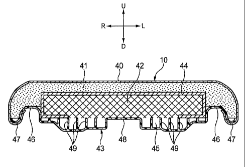
Referring to Figs. 2 and 3, the vehicular seat 10 includes a first cushion
member 41, a second
cushion member 42, and a covering sheet 44. Specifically, the first cushion
member 41
formed of urethane is covered with a seat skin 40. The second cushion member
42 formed of
a thermoplastic elastomer is disposed between the first cushion member 41 and
a bottom plate
43. The covering sheet 44 is disposed between the first cushion member 41 and
the second
cushion member 42. Note that, in the first embodiment of the present
invention, the second
cushion member 42 is disposed on the side of the rider's seat; nonetheless,
the second cushion
member 42 may also be disposed on the side of the pillion 10b. In Fig. 2, the
first cushion
member 41 is omitted for ease of understanding of a structure of the vehicular
seat 10.
WH-13705/cs
CA 02727897 2011-01-13
-8-
The bottom plate 43 is a sheet-like member formed of a synthetic resin.
Referring to Fig. 3,
the bottom plate 43 has a recessed portion 45 formed at a central portion
thereof, in which the
second cushion member 42 is fitted. The recessed portion 45 has a curved
portion 46 formed
on each of both end portions in a vehicle width direction. The curved portion
46 protrudes
upwardly and is formed continuously. The bottom plate 43 also has a seat skin
mounting
portion 47 formed continuously on each of outer end portions in the vehicle
width direction of
the curved portions 46. The seat skin mounting portion 47 has a substantially
J-shaped cross
section. The bottom plate 43 further has a protruding portion 48 formed
continuously at a
central portion of a bottom of the recessed portion 45. The protruding portion
48 supports a
lower surface of the second cushion member 42 and enhances stiffness of the
bottom plate 43.
A plurality of ribs 49 (a total of 12 on the left and right sides shown in
Fig. 3) is formed on an
upper surface of the bottom of the recessed portion 45. The ribs extend toward
the side of the
second cushion member 42 to support the lower surface of the second cushion
member 42
and enhance stiffness of the bottom plate 43.
The second cushion member 42 is formed by cutting a block-like thermoplastic
elastomer
base material. Referring to Fig. 3, the second cushion member 42 is formed
into a shape
having a rectangular cross section and fitted in the recessed portion 45 of
the bottom plate 43.
According to the first embodiment of the present invention, it is possible to
make the
occupant feel less corners of the second cushion member 42 when seated by
adjusting a
thickness of the first cushion member 41 and that of the covering sheet 44.
The vehicular seat
10 is thereby allowed to exhibit a uniform feel. The second cushion member 42
is a
thermoplastic elastomer striate body of an isotropic gel-like viscoelastic
body type that is
coupled three-dimensionally into a net-like thermoplastic elastomer.
Referring to Fig. 3, the covering sheet 44 is affixed to a surface of the
second cushion
member 42 on the side adjacent the first cushion member 41. The covering sheet
44 is not
affixed to part of a surface of the second cushion member 42 on the side of
the bottom plate
43. Specifically, the covering sheet 44 is affixed to an upper surface, side
surfaces, and part
of a bottom surface of the second cushion member 42.
The first cushion member 41 is formed integrally on a surface of the covering
sheet 44 affixed
to the second cushion member 42 by foaming a urethane material in molds 81, 82
to be
described later. This causes the covering sheet 44 to be in tight contact with
the first cushion
member 41 by a foaming pressure, facilitating clearance control.
WH-13705/ cs
CA 02727897 2011-01-13
-9-
As described heretofore, in the vehicular seat 10 according to the first
embodiment of the
present invention, the covering sheet 44 is disposed between the first cushion
member 41 and
the second cushion member 42. Even if the first cushion member 41 of urethane
is foamed to
be integrally formed on the second cushion member 42 of the thermoplastic
elastomer, the
foamed first cushion member 41 is blocked by the covering sheet 44. This
eliminates the
likelihood that the first cushion member 41 and the second cushion member 42
will be fused
together, so that favorable riding comfort of the vehicular seat 10 can be
achieved. In
addition, the first cushion member 41 can be foamed to be integrated with the
second cushion
member 42. This reduces the number of work processes involved, so that a
manufacturing
cost of the vehicular seat 10 can be reduced.
In the vehicular seat 10 according to the first embodiment of the present
invention, the
covering sheet 44 is affixed to a side of the second cushion member 42
adjacent the first
cushion member 41 and is not to part of a side of the second cushion member 42
adjacent the
bottom plate 43. Air inside the second cushion member 42 can therefore be
aspirated on the
side of the bottom plate 43 according to movement of the occupant, so that
favorable riding
comfort of the vehicular seat 10 can be achieved.
Additionally, in the vehicular seat 10 according to the first embodiment of
the present
invention, the ribs extending toward the side of the second cushion member 42
are disposed
on the upper surface of the bottom plate 43. The second cushion member 42 can
therefore be
effectively bled of air according to the movement of the occupant, so that
favorable riding
comfort of the vehicular seat 10 can be achieved.
Additionally, in the vehicular seat 10 according to the first embodiment of
the present
invention, the second cushion member 42 is formed by cutting operations into a
shape having
the rectangular cross section. This eliminates the need for forming an
obliquely cut surface
52a through cutting operations as in a second cushion member 52 of a second
embodiment of
the present invention to be described later. As a result, the manufacturing
cost of the
vehicular seat 10 can be further reduced.
A vehicular seat according to a second embodiment of the present invention
will be described
below with reference to Fig. 4. Like or corresponding parts are identified by
the same
reference numerals as those used for the first embodiment of the present
invention and
descriptions for those parts will be omitted or simplified.
WH-13705/ cs
CA 02727897 2011-01-13
-10-
Referring to Fig. 4, a vehicular seat 10 according to the second embodiment of
the present
invention includes a first cushion member 41, a second cushion member 52, and
a covering
sheet 44. More specifically, the first cushion member 41 formed of urethane is
covered with
a seat skin 40. The second cushion member 52 formed of a thermoplastic
elastomer is
disposed between the first cushion member 41 and a bottom plate 43. The
covering sheet 44
is disposed between the first cushion member 41 and the second cushion member
52.
The second cushion member 52 is formed by cutting a block-like thermoplastic
elastomer
base material. Referring to Fig. 4, the second cushion member 52 has a
straight-line
obliquely cut surface 52a on each side of an upper portion of outer end
portions in the vehicle
width direction thereof. The obliquely cut surface 52a is formed such that the
second cushion
member 52 has a thickness that gradually decreases toward the outside in the
vehicle width
direction.
As shown in Fig. 4, the covering sheet 44 is affixed to an upper surface, the
obliquely cut
surfaces 52a, side surfaces, and part of a bottom surface of the second
cushion member 52.
As described above, in the vehicular seat 10 according to the second
embodiment of the
present invention, the second cushion member 52 is formed to have the
obliquely cut surfaces
52a through cutting operations. This eliminates the need for forming a
protruding portion 62b
and an arcuate surface 62c by thermal forming as in a second cushion member 62
of a third
embodiment of the present invention to be described later. As a result, the
manufacturing
cost of the vehicular seat 10 can be reduced.
Additionally, in the vehicular seat 10 according to the second embodiment of
the present
invention, the second cushion member 52 has the obliquely cut surfaces 52a
formed at the
upper portions on the outer end portions in the vehicle width direction
thereof. This allows
an entire seat surface of the vehicular seat 10 to exhibit a uniform feel
during seating.
Other arrangements and effects are the same as those of the first embodiment
of the present
invention.
A vehicular seat according to a third embodiment of the present invention will
be described
below with reference to Fig. 5. Like or corresponding parts are identified by
the same
reference numerals as those used for the first embodiment of the present
invention and
descriptions for those parts will be omitted or simplified.
WH-13705/ cs
CA 02727897 2011-01-13
-11-
Referring to Fig. 5, a vehicular seat 10 according to the third embodiment of
the present
invention includes a first cushion member 41, a second cushion member 62, and
a covering
sheet 44. More specifically, the first cushion member 41 formed of urethane is
covered with
a seat skin 40. The second cushion member 62 formed of a thermoplastic
elastomer is
disposed between the first cushion member 41 and a bottom plate 43. The
covering sheet 44
is disposed between the first cushion member 41 and the second cushion member
52.
The second cushion member 62 is formed by thermally forming a block-like
thermoplastic
elastomer base material. Referring to Fig. 5, the second cushion member 62 has
a main unit
portion 62a and protruding portions 62b. More specifically, the main unit
portion 62a is
fitted into a recessed portion 45 in the bottom plate 43. Each of the
protruding portions 62b
protrudes outwardly from an outer end surface in the vehicle width direction
of the main unit
portion 62a and is placed on a curved portion 46 of the bottom plate 43. In
addition, an
arcuate surface 62c is formed at an upper corner of each of the protruding
portions 62b.
Additionally, referring to Fig. 5, the covering sheet 44 is affixed to an
upper surface of the
main unit portion 62a, upper surfaces, side surfaces, and bottom surfaces of
the protruding
portions 62b, and side surfaces of the main unit portion 62a of the second
cushion member
62.
As described above, in the vehicular seat 10 according to the third embodiment
of the present
invention, the second cushion member 62 includes the main unit portion 62a and
the
protruding portions 62b that protrude outwardly from the upper portions of the
outer end
surfaces in the vehicle width direction of the main unit portion 62a. Each of
the protruding
portions 62b includes the arcuate surface 62c formed at each of the upper
corners of the
protruding portions 62b. This allows both sides of the vehicular seat 10 to
exhibit a uniform
feel during seating. Riding comfort of the vehicular seat 10 can therefore be
further
enhanced.
Other arrangements and effects are the same as those of the first embodiment
of the present
invention.
The present invention has been described with particularity relative to the
detailed description
of the exemplary preferred first through third embodiments, in which the
present invention is
applied to the vehicular seat 10 of the motorcycle 1. The present invention
may still be
applied to a vehicular seat 71 of a four-wheeled vehicle as shown in Fig. 6 or
a watercraft seat
72 of a saddle riding type watercraft as shown in Fig. 7. In Fig. 6, the
second cushion
WH-13705/ cs
CA 02727897 2011-01-13
-12-
member 52 of the second embodiment of the present invention is used in the
vehicular seat 71
of the four-wheeled vehicle. The second cushion member 42 or 62 of the first
or third
embodiment of the present invention may instead be used. In Fig. 7, the second
cushion
member 42 of the first embodiment of the present invention is used in the
watercraft seat 72
of the saddle riding type watercraft. The second cushion member 52 or 62 of
the second or
third embodiment of the present invention may instead be used.
A method for making the vehicular seat or the watercraft seat according to an
embodiment of
the present invention will be described below with reference to Figs. 8 and 9.
In the
descriptions that follow, the vehicular seat 10 according to the second
embodiment of the
present invention will be used as an example.
The method for making the vehicular seat 10 includes the steps of. forming the
second
cushion member 52 of the thermoplastic elastomer of a net-like structure by
cutting (see Fig.
8(a)); affixing the covering sheet 44 generally to the second cushion member
52 excluding
part of the lower surface of the second cushion member 52 (see Fig. 8(b));
setting the second
cushion member 52, to which the covering sheet 44 is affixed, into a recessed
portion 81a
formed in a lower surface of an upper mold (a first mold) 81 (see Fig. 8(c));
loading a
urethane material 83 into a recessed portion 82b formed in an upper surface of
a lower mold
(a second mold) 82 (see Fig. 8(d)); closing the upper mold 81 and the lower
mold 82 (see Fig.
9(a)); foaming the urethane material 83 in a cavity 84 formed between the
upper mold 81 and
the lower mold 82 and integrally forming the first cushion member 41 on the
surface of the
covering sheet 44 affixed to the second cushion member 52 (see Fig. 9(b));
removing an
integrated assembly of the first cushion member 41, the second cushion member
52, and the
covering sheet 44 from the upper mold 81 and the lower mold 82 (see Fig.
9(c)); and
mounting the bottom plate 43 on a lower surface of the integrated assembly of
the first
cushion member 41, the second cushion member 52, and the covering sheet 44,
covering the
surface of the first cushion member 41 with the seat skin 40, and mounting the
seat skin 40 on
the seat skin mounting portion 47 of the bottom plate 43 (see Fig. 9(d)). The
vehicular seat
71 and the watercraft seat 72 are made by the same making processes.
As described above, the method for making the vehicular seat 10 according to
the
embodiment of the present invention includes the steps of. forming the second
cushion
member 52; affixing the covering sheet 44 generally to the second cushion
member 52
excluding part thereof, setting the second cushion member 52, to which the
covering sheet 44
is affixed, onto the upper mold 81; loading the urethane material 83 into the
lower mold;
closing the upper mold 81 and the lower mold 82; foaming the urethane material
83 and
WH-13705/cs
CA 02727897 2011-01-13
-13-
integrated assembly of the first cushion member 41, the second cushion member
52, and the
covering sheet 44, covering the surface of the first cushion member 41 with
the seat skin 40,
and mounting the seat skin 40 on the bottom plate 43. The vehicular seat 10
having the first
and second cushion members 41, 52 integrated together can be easily obtained
by foaming the
urethane material 83.
Although the foregoing describes the exemplary preferred embodiments, various
changes in
form and detail may be made therein without departing from the spirit and
scope of the
invention.
For example, the vehicular seat according to the embodiments of the present
invention are
suited to those of motorcycles and saddle riding type vehicles and of
automobiles and the
watercraft seat according to the embodiments of the present invention are
suited to those of
saddle riding type watercrafts. These are not the only possible applications
and the present
invention may be applied to seats in industrial vehicles, trains, aircraft,
and other various
types of vehicles.
WH-13705/cs