Note: Descriptions are shown in the official language in which they were submitted.
CA 02728040 2014-08-13
TRAILER
BACKGROUND
[0001] Commonly, the term trailer refers to vehicles used for transport of
goods and materials. A
semi-trailer is a trailer without a front axle. A large proportion of a
semitrailer's weight is
supported either by a road tractor or by a detachable front axle assembly
known as a dolly. A
semi-trailer is normally equipped with legs, called "landing gear," which can
be lowered to
support it when it is uncoupled.
SUMMARY OF THE DISCLOSURE
[0002] In one aspect, a trailer is disclosed (e.g., a semi-trailer). In one
approach, the trailer
includes a floor, a rear wheel assembly, and an elongated shell connected to
the floor. The floor
may include a top surface and a bottom surface. The floor extends continuously
from a front end
to a rear end. The elongated shell includes a bottom wall and side walls. The
side walls are
secured to the bottom surface of the floor. The elongated shell extends behind
the rear wheel
assembly. The top surface of the floor may be adapted to transport a payload.
The floor and the
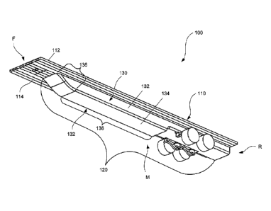
elongated shell define together a single, substantially hollow, internally
undivided, and
substantially closed torsion-resistant chamber with the bottom surface of the
floor defining a top
wall of the substantially hollow and closed torsion-resistant chamber. The
substantially closed
torsion-resistant chamber is free of lattice framework extending therein and
the elongated shell is
free of aperture that substantially degrades the resistance of the
substantially closed torsion-
resistant chamber. The substantially closed torsion-resistant chamber may
facilitate, for example,
a strategic distributing of mass located further from the neutral axis of the
trailer and/or a higher
stiffness to weight ratio. In one embodiment, the substantially closed torsion-
resistant chamber
comprises a plurality of interconnected plates. In one embodiment, the
substantially closed
torsion-resistant chamber comprises a plurality of interconnected extrusions.
[0003] The substantially closed torsion-resistant chamber is a structure that
is largely hollow,
with a mostly opening-free skin encompassing its outer perimeter, and is
constructed such that an
applied torque will cause a lower torsion deflection than a conventional
trailer of similar size and
load capacity. In one embodiment, the trailer may have a torsion deflection
(measured as angular
deformation 0), that is less than the torsion deflection of a conventional
trailer of similar size and
load capacity. In one embodiment, the angular deformation 0 of the trailer is
at least 50% less
than the angular deformation 0' of a conventional trailer. In one embodiment,
the trailer weighs at
-1-
CA 02728040 2014-08-13
least 10% less than the conventional trailer, and the trailer has a bending
resistance that is at least
equivalent to the bending resistance of the conventional trailer.
[0004] In one embodiment, the elongated shell is connected to at least one
bottom surface of the
floor, where, as connected, the elongated shell and the floor define the
substantially closed
torsion-resistant chamber. In one embodiment, the elongated shell defines
bottom and side
portions of the substantially closed torsion-resistant chamber, and the floor
defines top portions of
the substantially closed torsion-resistant chamber. In another embodiment, the
elongated shell
defines the top, bottom and side portions of the substantially closed torsion-
resistant chamber.
[0005] In one embodiment, the elongated shell includes a neck portion located
proximal the front
of the trailer. In one embodiment, the neck portion comprises a plurality of
supporting ribs. In one
embodiment, the elongated shell comprises a main body portion adjacent the
neck portion.
[0006] In one embodiment, the floor includes a plurality of elongated support
members. In one
embodiment, a first one of the plurality of elongated support members is
generally parallel to a
longitudinal axis of the trailer, and a second one of the plurality of
elongated support members is
transverse to the longitudinal axis of the trailer. In one embodiment, the
first one of the plurality
of elongated support members is located proximal the front of the trailer. In
one embodiment, the
second one of the plurality of elongated support members is located proximal
the middle and/or
rear of the trailer. In one embodiment, the first support member has a larger
height than the
second support member. In this embodiment, a transitional support member may
connect that first
support member and the second support member.
[0007] In one embodiment, at least one of the elongated support members
comprises one or more
shaped internal member, which is at least one of X-shaped, W-shaped, Y-shaped,
and I-shaped.
These shaped internal members may be arranged between a top member and a
bottom member. In
one embodiment, the elongated support member includes at least one thin member
stretching
between a shaped internal member and the top member. In one embodiment, the
elongated
support member includes at least one thin member stretching between the shaped
internal
member and the bottom member.
[0008] These and other aspects, advantages, and novel features of the instant
disclosure are set
forth in part in the description that follows and will become apparent to
those skilled in the art
upon examination of the following description and figures, or may be learned
by practicing the
technology of this disclosure.
BRIEF DESCRIPTION OF THE DRAWINGS
-2-
CA 02728040 2014-08-13
[0009] FIG. 1 illustrates one embodiment of a trailer.
[0010 ] FIG. 2a illustrates one embodiment of angular deformation of the
trailer of FIG. 1.
[0011] FIG. 2b illustrates one embodiment of angular deformation of a
conventional trailer.
[0012] FIG. 3 illustrates one embodiment of the elongated shell of FIG. 1
(excluding supporting
ribs).
[0013] FIG. 4 illustrates one embodiment of a first portion of the trailer of
FIG. 1.
[0014] FIG. 5a illustrates one embodiment of the floor of the trailer of FIG.
1.
[0015] FIG. 5b illustrates another embodiment of a floor of a trailer.
[0016] FIG. 5c illustrates another embodiment of a floor of a trailer.
[0017] FIG. 6 illustrates embodiments of support members of the floor of FIG.
5b.
[0018] FIG. 7a illustrates another embodiment of a support member of a floor.
[0019] FIG. 7b illustrates another embodiment of a support member of a floor.
[0020] FIG. 7c illustrates another embodiment of a support member of a floor.
[0021] FIG. 8a illustrates one embodiment of a transitional support member of
a floor.
[0022] FIG. 8b illustrates another embodiment of a transitional support member
of a floor.
[0023] FIG. 9 illustrates one embodiment of an end cap of a trailer.
[0024] FIG. 10 illustrates one embodiment of bending deformation of a trailer.
[0025] FIG. 11 illustrates one embodiment of a method for producing a trailer.
DETAILED DESCRIPTION
[0026] Reference will now be made in detail to the accompanying drawings,
which at least assist
in illustrating various pertinent embodiments of the present disclosure. FIG.
1 illustrates one
embodiment of a trailer 100. In the illustrated embodiment, the trailer 100
includes a floor 110
and an elongated shell 120. The floor 110 includes a top surface 112 and a
bottom surface 114,
and the elongated shell 120 is connected to the bottom surface 114 of the
floor 110. The top
surface 112 may be configured to carry a payload. In an embodiment, as
connected, the elongated
shell 120 and the floor 110 define a substantially closed torsion-resistant
chamber 130.
[0027] The substantially closed torsion-resistant chamber 130 is a structure
that is largely hollow,
with a mostly opening-free skin encompassing its outer perimeter, and is
constructed such that an
-3-
CA 02728040 2014-08-13
applied torque will cause a lower torsion deflection than a conventional
trailer having a similar
load capacity. The trailer 100 may also realize an equal or better bending
resistance than a
conventional trailer due to, at least in part, the substantially closed
torsion-resistant chamber 130.
In the illustrated embodiment, the substantially closed torsion-resistant
chamber 130 includes
lateral sides 132, a bottom 134, and a top (not illustrated), the top being
associated with the floor
110 of the trailer 100. These components may define a torsion-box
configuration. The
substantially closed torsion-resistant chamber 130 may include a first portion
136 (e.g., a neck)
associated with a front F of the trailer 100 and a second portion 138 (e.g., a
main body) associated
with a middle M and/or rear R of the trailer 100. The substantially closed
torsion-resistant
chamber may comprise a plurality of interconnected wrought products (e.g.,
wrought aluminum
products), such as sheets, plates, extrusions, and/or forgings. These products
may be
interconnected via suitable apparatus and/or methods, such as welding,
fasteners and the like.
Other materials and/or methods may be used to produce the substantially closed
torsion-resistant
chamber.
[0028] Since the trailer 100 includes the substantially closed torsion-
resistant chamber 130, the
trailer 100 may be torsion resistant and/or bending resistant relative to
conventional trailers of
similar size (e.g., dimensions and/or mass) and load capacity. Since the
trailer 100 includes the
substantially closed torsion-resistant chamber 130. The trailer 100 may
realize, among other
things, (i) a strategic distribution of mass located further from the neutral
axis (e.g., the
longitudinal axis through the center of gravity of the trailer 100); and/or
(ii) a higher stiffness-to-
weight ratio. These benefits may at least facilitate better on-road
performance of the trailer 100.
For example, better stiffness coupled with lighter weight may provide the
ability to haul bigger
payloads, resulting in a more rapid return on investment. Furthermore, when
made of aluminum,
the trailer 100 may realize longer lifetime than a conventional trailer.
[0029] One or more of the above-noted benefits may be realized due to the
ability of the
substantially closed torsion-resistant chamber 130 to withstand angular
deformation. For
example, and with reference now to FIG. 2a-2b, the floor 110 of the trailer
100 may have a
torsion deflection (measured as angular deformation 0), that is less than the
torsion deflection
(measured as angular deformation 0') of a floor 190 of a conventional trailer
180 having a similar
size and load capacity. In one embodiment, the angular deformation 0 of the
trailer 100 may be at
least 5% better than the angular deformation 0' of a conventional trailer 180.
For example, if the
new trailer 100 realizes an angular deformation of 17.14 , and the
conventional trailer realizes an
angular deformation of 18.00 , the new trailer 100 has 5% better angular
deformation than that of
-4-
CA 02728040 2014-08-13
the conventional trailer ((18-17.14)117.14 = 5%). In other embodiments, the
angular deformation
0 of the trailer 100 is at least 10% better, or at least 25% better, or at
least 50% better, or at least
75% better, or at least 100% better, or at least 200% better, or at least 300%
better, or at least
400% better, or at least 500% better than the angular deformation 0 of the
conventional trailer
180. In an embodiment, angular deformation of a trailer (new or conventional)
may be
determined using finite element analysis software (e.g., Unigraphics,
Nastran).
[0030] As described above, the substantially closed torsion-resistant chamber
generally includes
lateral sides 132, a bottom 134 and a top (not illustrated). The dimensions of
the substantially
closed torsion-resistant chamber 130 may be tailored relative to the size of
the trailer. For
example, a standard flat-bed trailer having a length of about 50 to 60 feet
(e.g., about 53 feet), the
substantially closed torsion-resistant chamber 130 may have a height (e.g.,
from the bottom 134
to the top) in the range of from about 18 to about 22 inches, a width (e.g.,
from lateral side to
lateral side 132) in the range of from about 40 to about 50 inches, and a
length (from the front of
the first portion 136 to the rear of the second portion 138) in the range of
from about 40 to about
48 feet. These dimensions and the ratios thereof (e.g., height to width) may
facilitate at least a
portion of the resistance of the substantially closed torsion-resistant
chamber 130. Other trailers
may have other lengths, such as in the range of 25 to 60 feet, and the
dimension of the
substantially closed torsion-resistant chamber 130 may be tailored relative to
the size of the
trailer, so long as the torsion resistance of the trailer is maintained.
[0031] As described above, the trailer 100 includes an elongated shell 120,
one embodiment of
which is illustrated in FIG. 3. In the illustrated embodiment, and with
reference to FIGS. 1 and 3,
the elongated shell 120 is a long, shell-like structure that is at least a
portion of the substantially
closed torsion-resistant chamber 130. In one embodiment, as connected, the
elongated shell 120
and the bottom surface 114 of the floor 110 define the substantially closed
torsion-resistant
chamber 130. In other words, the elongated shell 120 may define bottom 134 and
lateral side
portions 132 of the substantially closed torsion-resistant chamber 130, and
the bottom surface 114
of the floor 110 may define top portions (not illustrated) of the
substantially closed torsion-
resistant chamber 130. In other embodiments, the elongated shell 120 may
define at least the top,
bottom 134, and lateral side portions 132 of the substantially closed torsion-
resistant chamber
130. In such an embodiment, the floor 110 may make up little or none of the
substantially closed
torsion-resistant chamber 130. In an embodiment, the elongated shell 120 may
be connected to
the floor 110 via welding (e.g., MIG welding), bonding or other methods. In an
embodiment, the
-5-
CA 02728040 2014-08-13
elongated shell 120 may be connected to one or more support members of the
floor, described in
further detail below.
[0032] The elongated shell 120 may include a neck portion N. In one
embodiment, and with
continued reference to FIGS. 1 and 3, the neck portion N may be located
proximal the front F of
the trailer 100. The neck portion gradually decreases the height of the
elongated shell (e.g., tapers
down) prior to reaching the front end of the trailer so as to provide room for
a fifth wheel or
landing gear, for instance. In an embodiment, the elongated shell 120 includes
a main body MB
portion adjacent the neck portion N. The neck portion N and/or the main body
portion MB may
have a regular or non-regular cross-sectional profile (e.g., when viewed from
a side of the trailer
100). The elongated shell 120 may be connected to a suspension system SS of
the trailer 100 via
conventional apparatus and methods. The suspension system SS may be a system
of springs,
shock absorbers, linkages, and/or other components that can connect the floor
and/or elongated
shell to one or more wheels.
[0033] Since the shape of the neck N generally decreases the height of the
lateral sides of the
substantially closed torsion-resistant chamber, the torsion resistance and/or
bending resistance of
the neck may be less than the main body portions of the substantially closed
torsion-resistant
chamber. Thus, in an embodiment, and with reference now to FIG. 4, the neck
portion N may
include one or more supporting ribs 412, 414. The supporting ribs 412, 414 may
be, for example,
I-beams or other rigid beams. The ends of the supporting ribs 412, 414 may
connect to the
elongated shell and/or floor. In an embodiment, a first portion 416 of the
supporting rib 412 or
414 connects to the elongated shell 120 (e.g., a first lateral side and/or
bottom of the elongated
shell). In a related embodiment, a second portion 418 of supporting rib 412
connects to another
portion the elongated shell 120 (e.g., a second side of the elongated shell).
In another
embodiment, a second portion 420 of supporting rib 414 connects to the floor
(not illustrated). A
plurality of supporting ribs may be utilized and each may connect with the
elongated shell and/or
floor. In the illustrated embodiment, the main body portion MB is generally
free from supporting
ribs 412, 414. In another embodiment, the main body portion MB may comprise
one or more ribs
so as to restrict angular deformation and/or bending deformation of the
elongated shell.
[0034] Referring back to FIG. 3, the elongated shell 120 may be produced via
various methods.
In an embodiment, the elongated shell 120 comprises a number of connected
sheets. These sheets
may be substantially flat, or may have bends, curves, or other non-regular
shapes, or a
combination thereof. In an embodiment, these sheets may be connected via
welding (e.g., MIG
welding) or other methods.
-6-
CA 02728040 2014-08-13
[0035] In an embodiment, the elongated shell 120 comprises a number of
connected extrusions.
In an embodiment, these extrusions may be connected via welding (e.g., MIG
welding) or other
methods. For example, two extrusions may each have a first edge/surface
connected to the bottom
surface of the floor 114 via welding or other methods, and a second
edge/surface connected to the
other extrusion via welding or other methods.
[0036] In an embodiment, the elongated shell 120 comprises a number of
connected sheets and
extrusions. In an embodiment, the elongated shell 120 comprises a U-shape
configuration (as
viewed along the longitudinal axis of the trailer 100). Such U-shape
configuration can include
any curvature (e.g., exponential or hyperbolic) and/or flat portions. Unlike
the floor, the elongated
shell is generally not adapted to carry / contain a payload. However, it is
anticipated that, in some
embodiments, the elongated shell could be adapted to include at least a
portion of the payload. A
payload is the main cargo intended for delivery from a first location to a
distant second location
as carried via the trailer.
[0037] In an embodiment, the elongated shell 120 may comprise one or more
apertures (not
illustrated) so long as such apertures do not substantially degrade the
resistance of the
substantially closed torsion-resistant chamber 130. For example, the elongated
shell 120 may
include apertures for drainage. In an embodiment, the apertures may be
reinforced (e.g., via a ring
of welded metal surrounding the aperture) to compensate for any loss of
resistance caused by the
apertures.
[0038] As noted, the trailer 100 includes a floor 110, one embodiment of which
is illustrated in
FIGS. 1 and 5a. The floor 110 may be a load-bearing structure of the trailer
100 having a
generally planar surface, and which is configured to carry a payload, such as,
for instance, a
plurality of steel coils. The floor 110 may be made of metal (e.g., aluminum
alloys), composite
materials, other generally rigid materials (e.g., wood), or any combination of
the above. The floor
110 may comprise a top surface 112, a bottom surface 114, and one or more side
surfaces 516, for
example, front, back, left, and right surfaces.
[0039] To facilitate adequate support of the payload, the floor 110 may
comprise a plurality of
support members 520. The support members 520 may be elongated load-bearing
components of
the floor 110. In an embodiment, the floor 110 may comprise a plurality of
interconnected
support members 520, where each support member 520 is connected to at least
one other support
member 520 (e.g., via two of the long sides of each support member 520). In
other words, a
plurality of support members 520 may be attached side to side in order to form
at least a portion
of a floor. Attachment may be made via welding (e.g., MIG welding) or other
methods. In an
-7-
CA 02728040 2014-08-13
embodiment, a majority of the support members 520 face a coincidental
direction (e.g., are
parallel to each other). In an embodiment, the support members are
substantially hollow.
[0040] The support members 520 of the floor 110 may be arranged in any
suitable configuration.
For instance, and with reference now to FIG. 5b, a first portion 510 of a
floor 110' may comprise
a first plurality of support members 521, which face a first direction (e.g.,
a front or rear of the
trailer). In a related embodiment, a second portion 512 of the floor 110' may
comprise support
members 523, which face in a second direction (a direction different than the
first direction, such
as a side of the trailer). In an embodiment, the first portion 510 of the
floor 110' is related to a
front F of the trailer (e.g., near where the trailer 100 connects to a self-
propelled vehicle). In a
related embodiment, the second portion 512 of the floor 110' is related to a
middle M and/or rear
R of the trailer. The elongated support members may have a height, for
example, in the range of 2
to 6 inches, and a width, for example, in the range of 4 to 24 inches. The
length of the elongated
support members may be based on location and orientation within the floor. For
example, the
length of the elongated support members may be in the range of from about 2 to
about 53 feet. In
some embodiments, the length of the elongated support members is in the range
of from about 4
to about 27 feet, or in the range of from about 6 to about 15 feet, or in the
range of from about 8
to about 12 feet.
[0041] As illustrated in FIG. 5b, the first plurality of elongated support
members 521 have their
longitudinal axes generally parallel to the longitudinal axis of the floor,
and the second plurality
of elongated support members 523 have their longitudinal axes generally
transverse to the
longitudinal axis of the floor. As used herein, transverse means lying or
being across, or in a
crosswise direction. In one embodiment, transverse means perpendicular. The
embodiment of
FIG. 5b may be useful, for example, in mitigating stress proximal the neck N
of the substantially
closed torsion-resistant chamber. Such a configuration may provide higher
strength at lower
weights than conventional support members. In the illustrated embodiment, the
elongated support
members 521, 523 have a length less than the length of the floor 110.
[0042] In another embodiment, illustrated in FIG. Sc, elongated support
members 525 have a
length less than the length of a floor 110", but are configured coincidental
to (e.g., parallel to) the
longitudinal axis of the floor 110". As illustrated, the elongated support
members 525 may be
configured in a staggered arrangement. In such an embodiment, the elongated
support members
525 may be connected to each other via one or more end(s) or lateral side(s)
of each other. The
embodiment of FIG. 5 c may be useful, for example, when employed in the second
portion 512
(FIG. 5b) of the trailer 110'.
-8-
CA 02728040 2014-08-13
[0043] The embodiment illustrated in FIG. 5a is useful in accordance with the
instant disclosure.
However, the challenge and expense of extruding elongated support members
roughly equal to
the length of the floor may make the embodiments illustrated in FIGS. 5b and
5c an easier
implementation. Thus, the elongated support members of FIGS. 5b and 5c may be
manufactured
more easily and at less cost than those of FIG. 5 a. For example, the length
of the first plurality of
elongated support member 521 of FIG. 5b may be in the range of 10-12 feet. The
length of the
second plurality of elongated support members 523 of FIG. 5b, may be about the
same as the
desired width of the floor 110', or in the range of about 7-9 feet.
[0044] The floor may be assembled from support members having similar or
differing cross-
sectional profiles. In some embodiments, at least some of the support members
have the same
cross-sectional profile. In some embodiments, at least some of the support
members have
differing cross-sectional profiles. For instance, and with reference now to
FIG. 6, a first plurality
of support members 610 may have a first profile 612, and a second plurality of
support members
620 may have a second profile 622. In the illustrated embodiment, the first
profile 612 includes
crossing or diagonally intersecting internal members 614 (e.g., X-shaped
internal members)
arranged between a top outer member 616 and a bottom outer member 618. The top
outer
member 616 and the bottom outer member 618 may be generally parallel to each
other. In one
embodiment, a thin member 630 may stretch between (i) the diagonally
intersecting members 614
and (ii) the top outer member 616 and/or the bottom outer member 618. In some
embodiments,
not illustrated, the support members may include sidewalls (not illustrated).
[0045] The internal members of the elongated support members may be utilized
to increase the
load bearing capacity of the elongated support members and/or reduce the size
and/or weight of
the elongated support members (and hence the trailer). The illustrated
embodiment of FIG. 6
includes X-shaped internal members, which may include one or more protruding
vertical
members (illustrated) or horizontal members (not illustrated). Other internal
member
configurations may be utilized. For instance, any of an X-shaped, V-shaped, W-
shaped, I-shaped
or other alphabetic and/or numeric shaped internal members may be used. For
example, and with
reference to FIG. 7a, a support member 700 may include a V-shaped internal
member 714
connected to a top member 716 and a bottom member 718. The support member 700
may also
include a thin vertical member 730 stretching from the V-shaped member to one
of the top 716
and/or bottom 718 members (depending on the orientation of the "V").
[0046] In some embodiments, the internal members of the elongated support
member may form
triangular, trapezoidal, or other geometric shapes within the chamber of the
elongated support
-9-
CA 02728040 2014-08-13
member. The internal members may be oriented normally (upwards), sideways or
upside-down,
as appropriate. The internal members generally stretch between the top and
bottom members of
such support members. However, in some instances, in sideways (and perhaps in
other
orientations) such internal members may stretch between one or more sidewalls
and one or more
of the top or bottom members. In some embodiments, one or more elongated
support members
may be free of internal members.
[0047] The support members may be produced (e.g., extruded) in single
sections, as illustrated
above, or in a plurality of sections. For example, and with reference now to
FIGS. 7b and 7c,
support members 750, 780 may include a plurality of X-shaped, V-shaped, W-
shaped, I-shaped or
other shaped internal members 752, 782 stretching between top members 754, 784
and bottom
members 756, 786. Such support members may be useful, for example, in reducing
the amount of
effort required to produce a floor of a trailer. Such support members 750, 780
may have a width
in the range of from about 8 to about 24 inches, whereas the above-described
single section
support members may have a width in the range of from about 4 to about 8
inches. Other internal
member configurations may be employed.
[0048] Support members may be made of metal (e.g., aluminum alloys), composite
materials,
other generally rigid materials (e.g., wood), or any combination of the above.
In an embodiment,
support members may be extruded. In an embodiment support members may be
produced from a
plurality of components (e.g., top horizontal thin member, bottom horizontal
thin member, side
members, internal members) connected via welding (e.g., MIG) or other methods.
In an
embodiment, a support member is produced via a single extrusion. In one
embodiment, at least
some of the support members are produced from an aluminum alloy. The aluminum
alloy may be
any of a 2XXX, 3XXX, 4XXX, 5XXX, 6XXX, 7XXX or 8XXX series aluminum alloy. In
one
embodiment, a support member and/or at least some of the elongated shell is a
6XXX series
alloy, such as AA6061.
[0049] In another embodiment, a first plurality of support members has a first
set of dimensions
(e.g., a height of 2.5 inches) and a second plurality of support members has a
second set of
dimensions (e.g., a height of 3.5 inches). For example, in the front F of a
trailer, it may be useful
to include larger (e.g., thicker, and/or taller) elongated support members
since the front F of the
trailer may experience differing stresses than middle M and/or rear R portions
of the trailer.
Hence, in one embodiment, smaller (e.g., thinner and/or shorter), elongated
support members may
be used in the middle M and/or rear R portions of a floor of a trailer (e.g.,
section 512 of FIG. 5b),
-10-
CA 02728040 2014-08-13
and larger elongated support members may be used in front F portions of a
floor of a trailer (e.g.,
section 510 of FIG. 5b).
[0050] Given an embodiment in which some support members have differing
dimensions,
transitional support members may be used to transition between these support
members. For
instance, and with reference now to FIG. 8a, a transitional support member 800
may include a
first side portion 830, a middle portion 810, and a second side portion 840.
The first side portion
830 may be configured / sized to cooperatively engage with a first elongated
support member (not
illustrated) of a similar size. For instance, the first side portion 830 may
be attached to the first
elongated side member via welding, mechanical attachment or other apparatus /
methods.
Likewise, the second side portion 840 may be configured / sized to cooperative
engage with a
second elongated support member (not illustrated) of a similar size. The first
and second side
portions may include internal members 832, 842 similar to those of the
elongated support
members, and thus may include any of the X-shaped, V-shaped, W-shaped, I-
shaped or other
shaped internal members, as described above.
[0051] The middle portion 810 of the transitional support member is generally
asymmetric as it is
configured to transition between the first side portion 830 and the second
side portion 840, which
are of different sizes. In the illustrated embodiment, the middle portion 810
has a generally
trapezoidal shape; a generally parallel first side member 812 and second side
member 814, and a
third member 816 that is not parallel to a portion of a fourth member 818, but
is orthogonal to the
first and second side members 812, 814. Other geometric configurations may be
utilized. In an
embodiment, the first side member 812 has a height about equal to a height of
the first side
portion 830. The second side member 814 has a height about equal to a height
of the second side
portion 840. The middle member 810 may include internal members 820, such as
any of the
above-described internal members.
[0052] In the illustrated embodiment of FIG. 8a, the first and second side
portions 830, 840
include internal members 832, 842. In other embodiments, the first and/or
second side portions
830, 840 may be free of internal members. For example, and with reference now
to FIG. 8b, a
transitional support member 850 includes a first side portion 860, a middle
portion 810 and a
second side portion 870. The first side portion 860 includes some internal
members 862 having a
sideways V-shaped configuration. The second side portion 870 is free of
internal members. Other
configurations may be utilized. For example, in some instances, both side
members of a
transitional support member may be free of internal members.
-11-
CA 02728040 2014-08-13
[0053] The trailer may also include an end cap. For example, and with
reference to FIG. 9, an end
cap 900 may be located near the rear R of a trailer. The end cap 900 is an
optional component and
is not considered a part of the substantially closed torsion-resistant
chamber. The end cap 900
may be open, closed, partially closed, or may include a storage fixture. Thus,
in some
embodiments, a trailer at least includes (i) a substantially closed torsion-
resistant chamber; (ii) an
end cap proximal to / connected to a substantially closed torsion-resistant
chamber; and (iii) a
floor.
[0054] As noted, the instantly disclosed trailers may realize equal or better
bending deformation
than a conventional trailer of similar mass. Bending deformation is the amount
an object bends
(non-torsionally) when a force is applied to the object. One method for
measuring bending
deformation is to measure the amount an object is displaced from its normal
(non-loaded
position) when a load is applied to the object. For example, and with
reference now to FIG. 10,
the bending deformation of a trailer may be measured by measuring a height of
the floor before
and after a load is applied to the trailer. In the illustrated embodiment, the
vertical distance "d" is
the difference between the height of the floor before and after the load is
applied to the trailer.
Different trailers may bend at different locations, and thus the vertical
distance "d" may be the
difference between (i) the highest point of the floor when the trailer is in
an unloaded condition
and (ii) the lowest point of the floor when the trailer is in a loaded
condition.
[0055] In some embodiments, the trailer may have a reduced mass and realize
increased torsion
resistance and/or equal or better bending resistance than a conventional
trailer of similar load
capacity. For example, the instantly disclosed trailers may have a frame
weight (i.e., not including
tires, axles, suspension, accessories, and the like) in the range of about
4500 to about 5500
pounds (e.g., about 5000 pounds). A conventional trailer of similar load
capacity may have a
frame weight of at least about 6500 pounds. The new trailer may have a regular
weight (including
frame, tires, axle, suspension accessories, and the like) of about 7800 to
about 8800 pounds, and
the conventional trailer may have a regular weight of at least about 9800
pounds. Thus, the
instantly disclosed trailers may have a substantially reduced weight (frame or
regular), such as
about 10% less, or 15% less, or 20% less, or 25% less weight than a
conventional trailer of
similar load capacity, but realize at least one of (i) equal or better torsion
resistance than the
conventional trailer and (ii) equal or better bending resistance than the
conventional trailer.
[0056] Methods of producing trailers having a substantially closed torsion-
resistant chamber are
also provided. In one embodiment, and with reference now to FIG. 11, a method
may include the
-12-
CA 02728040 2014-08-13
steps of producing an elongated shell 1110, producing a floor 1120, and
producing a substantially
closed torsion-resistant chamber 1130.
[0057] The step of producing the substantially closed torsion-resistant
chamber 1130 is at least
partially dependent on step 1110, and may be fully dependent on step 1110 or
partially dependent
on both steps 1110 and 1120. For example, when the elongated shell makes up
the lateral sides
and bottom of the substantially closed torsion-resistant chamber and the floor
makes up the top of
the substantially closed torsion-resistant chamber, step 1130 is partially
dependent on both steps
1110 and 1120. In this embodiment, when the elongated shell is connected to
the floor, the floor
in combination with the elongated shell defines at least a majority of the
substantially closed
torsion-resistant chamber. In another instance, when the elongated shell makes
up the lateral sides
and bottom of the substantially closed torsion-resistant chamber as well as
the top of the
substantially closed torsion-resistant chamber (and the floor makes up none or
very little of the
substantially closed torsion-resistant chamber), step 1130 is completely
dependent, or nearly
completely dependent, upon step 1110.
[0058] As described above, the producing the elongated shell step 1110 may be
completed by
connecting sheets, extrusions or other components together to form a shell-
like structure. As
described above, the producing the floor step 1120 may be completed by
connecting a plurality of
support members together. As described above, the support members may
connected in various
manners and orientations to produce a lightweight, rugged and/or durable
floor.
[0059] As connected, the elongated shell and the floor may produce a trailer
having a
substantially closed torsion-resistant chamber 1140. Since the trailer is more
torsion resistant than
conventional trailers of similar size and load capacity, the trailer may be
more lightweight and/or
able to haul larger payloads 1150.
[0060] The trailer may be a load-bearing structure capable of transporting a
payload via
connection to a self-propelled vehicle. In an embodiment, the trailer is a
semi-trailer. In an
embodiment, the trailer is a flatbed trailer. The trailer may have a
longitudinal axis. The
longitudinal axis is generally along the long axis of an object, in this case
along the long axis of
the trailer. A self-propelled vehicle is a vehicle having a means of
propulsion.
EXAMPLE
[0061] To simulate the torsion resistance of the newly disclosed trailers
relative to a conventional
trailer, finite element analysis software is employed. The conventional
trailer has a standard
double I-beam configuration connected to the bottom of its floor (e.g.,
flatbed trailers produced
-13-
CA 02728040 2014-08-13
by FONTAINE TRAILER COMPANY). The new trailer utilizes a substantially closed
torsion-
resistant chamber connected to the bottom of its floor. The conventional
trailer and the new trailer
are of similar size and load capacity. The back tires of each trailer are
simulated to be
immoveable (e.g., held in) concrete. A simulated downward force of 10,000 lbf
is placed on the
right front corner of both trailers while a simulated upward force of 10,000
lbf is placed on the
left front corner of both trailers. The conventional trailer simulates an
angular deformation of
about 18 . The new trailer simulates an angular deformation of about 2 , or
about 800% better
than the angular deformation of the conventional trailer. The bending
deformation of the new
trailer is at least about equivalent to the conventional trailer.
[0062] The scope of the claims should not be limited by the embodiments set
forth in the
examples, but should be given the broadest interpretation consistent with the
description as a
whole.
-14-