Note: Descriptions are shown in the official language in which they were submitted.
CA 02728190 2010-12-15
WO 2010/004253 PCT/GB2009/001492
Device and method for making solid beads
The present invention relates to a microfluidic device for
the manufacture of solid beads (typically, but not
exclusively, polymer beads containing some form of
pharmaceutically active agent) and a method of making such
beads.
Many methods are known for the manufacture of small,
polymeric beads containing some form of pharmaceutically
active agent. Such beads are used, especially but not
exclusively, for the controlled release parenteral delivery
of the active agent within the human or animal body.
Illustrative therapeutic areas in which controlled release
parenteral delivery may be particularly applicable include,
for example, fertility treatment, hormone therapy, protein
therapy, infection treatments (antibiotics and antifungals),
cancer therapy, post-operative pain treatment, chronic pain
treatment, vaccination/immunization, treatment of disorders
of the central nervous system, and immunosupression. The
advantages of controlled release parenteral delivery in
those and other therapeutic areas are well-documented and
may include, for example, one or more of the following:
improvement of the therapeutic response; improved safety
(since, as compared with conventional parenteral dosage
forms, less drug is required and the drug may be targeted to
the in vivo site, avoiding high systemic levels); and
improved patient compliance (through the possibility of
lower dosing frequency and simpler dosage regimes).
Typically, polymer beads can be used to effect controlled
release of a therapeutic agent over periods of months.
CA 02728190 2010-12-15
WO 2010/004253 PCT/GB2009/001492
2
Most methods for the manufacture of polymeric beads for
therapeutics use solutions or mixtures of polymer and active
agent to make liquid droplets from which solid beads are
then made. Several techniques may be used to generate the
liquid droplets, such as stirring of the solution/mixture or
static mixing. These techniques generate beads with a broad
distribution of bead sizes. Alternative techniques include
dripping and spray formation which may also lead to the
production of beads with a broad distribution of bead sizes.
The liquid droplets generated by such methods may then be
treated to remove the solvent. This is typically achieved by
admixture of the droplets with large amounts of anti-solvent
or by evaporation. This may. lead to relatively large amounts
of residual solvent in the solid beads and may also lead to
the generation of beads with a broad distribution of bead
sizes.
The present invention is addressed at solving one or
more of the above-mentioned problems.
In accordance with a first aspect of the present
invention, there is provided a microfluidic device
comprising:
a carrier fluid conduit for the delivery of a carrier fluid;
a functional fluid conduit for the delivery of a functional
fluid which is immiscible with the carrier fluid, the
functional fluid conduit meeting the carrier fluid conduit
at a junction region so that, in use, a flow of droplets of
functional fluid in carrier fluid is formed at or downstream
of the junction region;
a cooling conduit arranged for receiving the segmented flow
from the junction region;
a cooler operable to cool fluid in the cooling conduit; and
CA 02728190 2010-12-15
WO 2010/004253 PCT/GB2009/001492
3
a desolvating conduit arranged for receiving fluid from the
cooling conduit, the device being provided with an anti-
solvent inlet for introducing an anti-solvent into the
desolvating conduit.
The device of the present invention facilitates the
manufacture of solid beads having beneficial size
distribution characteristics and no more than a small amount
of solvent remaining in the solid bead.
The functional fluid typically comprises a solution
comprising a solvent and a solute, the solute typically
comprising a polymer. The components of the functional fluid
are preferably so chosen that the droplets of functional
fluid solidify when cooled in the cooling conduit to form
solid droplets. The droplets may, for example, be frozen or
in the form of a gel. A gel is defined, herein as a substance
which acts as a solid in the device of the present invention
(i.e. deforms elastically and recovers and does not flow as
a liquid would flow). In some circumstances, the droplets of
functional fluid when cooled in the cooling conduit may not
form a solid, but rather may be a liquid, typically of a
high viscosity.
The components of the functional fluid may be
premixed, but may instead be combined within the substrate,
for example by means of two converging conduits. The
polymer typically has a low solubility in the anti-solvent,
whilst the solvent is miscible with the anti-solvent. The
addition of the anti-solvent typically causes the solvent to
pass out of the droplets, thus producing a solid bead.
The device may'comprise a plurality of carrier fluid
conduit for the delivery of a carrier fluid, the functional
fluid conduit meeting the carrier fluid conduits at a
junction region so that, in use, a flow of droplets of
CA 02728190 2010-12-15
WO 2010/004253 PCT/GB2009/001492
4
functional fluid in carrier fluid is formed at or downstream
.of the junction region.
The conduits mentioned above need not be discretely-
identifiable conduits. For example, the cooling conduit and
carrier fluid conduit may be merged into one another.
The cooler may comprise a cooling body comprising a
thermally conductive material (such as a metal, for example,
316 stainless steel or aluminium). The cooling body is
typically cooled when the cooler is operated. The cooling of
the cooling body may be used to cool the cooling conduit by
thermal conduction. The cooling body may be provided with a
chilling channel for the carriage of a chilling fluid. The
passage of a chilling fluid (typically a cold liquid)
through the chilling channel causes the cooling body to
cool. The chilling fluid preferably has a melting point of
lower than -50 C. The chilling fluid, is typically cooled
externally of the, device. The chilling fluid may be cooled
by any suitable refrigeration device, for example a Julabo
refrigerated circulator.
The cooling body of the cooler may further be provided
with a heater. Such a heater may be used to heat the body;
this may be useful in thawing any frozen liquids which may
block any of the conduits of the device and for controlling
the temperature of the anti-solvent and of the desolvation
process.
A cooling body need not be provided. For example, the
cooling conduit may be provided in a substrate of the
microfluidic device, wherein the substrate is provided with
a chilling channel for the carriage of a chilling fluid, the
cooling conduit being in thermal communication with the
chilling channel so that fluid in the cooling conduit may be
cooled by chilling fluid in the chilling channel.
CA 02728190 2010-12-15
WO 2010/004253 PCT/GB2009/001492
The device may be provided with a second thermally
conductive body, the second thermally conductive body being
associated with the carrier fluid conduit and the functional
fluid conduit. The second thermally conductive body may be
5 provided with a heater and/or cooler operable to regulate
the temperature of liquids in the carrier fluid conduit and
functional fluid conduit.
A thermally insulating gap may be provided between the
body of the cooler and the second thermally conductive body.
The thermally insulating gap may comprise a thermally
insulating material, such as air. The gap helps inhibit
cooling of the carrier fluid conduit and functional fluid
conduit when the cooler is used to cool the cooling conduit.
The second thermally conductive body may be provided
with a carrier fluid inlet for providing fluid to the
carrier fluid conduit. The second thermally conductive body
may be provided with a functional fluid inlet for providing
fluid to the functional fluid conduit.
It is preferred that the device comprises one or more
anti-solvent delivery conduits for delivering anti-solvent
to the desolvating conduit via the anti-solvent inlet.
It is preferred that the cooling conduit arranged for
receiving the segmented flow from the junction region is
provided in a substrate (for example, by removing material
from a substrate by milling or by laser action).
It is preferred that one or more of the carrier fluid
conduit, the functional fluid conduit, the desolvating
conduit and the anti-solvent delivery conduit(s) are
provided in a substrate.
It is further preferred that the substrate is in
thermal contact with a cooling part of the cooler. If the
cooler comprises a body of thermally conductive material, it
CA 02728190 2010-12-15
WO 2010/004253 PCT/GB2009/001492
6
is preferred that the substrate is in intimate contact with
the body of thermally conductive material.
If the cooler comprises a body of thermally conductive
material, the body-may be provided with one or more fluid
inlets for delivering fluid to the anti-solvent delivery
conduit (if present).
The term "microfluidic" is generally well-understood by
those skilled in the art. The conduits in such microfluidic
devices typically have widths of less than 2mm, preferably
less than lmm and more preferably from 0.1 to 0.5mm. The
depths of the conduits are typically less than 2mm,
preferably less than lmm and more preferably from 0.1mm to
0.5mm.
The flow rates of the fluids through the various
conduits will depend, inter alia, on the cross-sectional
area of the conduits. The flow rate, for example, of the
functional fluid through the functional fluid conduit may
typically be from about 0.01 to 0.2 ml/hour, especially 0.05
to 0.2 ml/hour (if the conduit has a cross-section of about
0.05mm x 0.15mm). The flow rate, for example, of the
functional fluid through the.functional fluid conduit may
typically be from about 1 to 20 ml/hour, (if the conduit has
a cross-section of about 2mm x 2mm). Such flow rates may be
used when wanting to make larger particles, such as,those
which may be used in assays. The flow rate of the carrier
fluid may typically be from about 1 to 4ml/hour, especially
2 to 3ml/hour (if the conduit has a cross-section of about
0.3mm x 0.3mm). The flow rate of the carrier fluid may
typically be from about 5 to 30m1/hour (if the conduit has a
cross-section of about 2mm x 2mm). Such flow rates may be
used when wanting to make larger particles, such as those
which may be used in assays. The flow rate of the anti-
CA 02728190 2010-12-15
WO 2010/004253 PCT/GB2009/001492
7
solvent may typically be from about 0.25 to 3 ml/hour,
especially 0.5 to 2ml/hour (if the conduit has a cross-
section of about 0.3mm x 0.3mm). The flow rate of the anti-
solvent is preferably so selected that, in the desolvating
conduit, the volume of anti-solvent is lower than the volume
of carrier fluid whilst being sufficient to ensure that
there is a high probability of contact between the cooled
droplets of functional fluid and the carrier fluid/anti-
solvent interface. By way of illustration the flow rates may
in some embodiments be such that the volume of carrier fluid
is from 1 to 4 times the volume of anti-solvent. The flow
rate of the anti-solvent may typically be from about 10 to
20ml/hour (if the conduit has a cross-section of between lmm
x lmm and 2mm x 2mm). Such flow rates may be used when
wanting to make larger particles, such as those which may be
used in assays.
It is preferred that the de'solvating conduit has a
larger cross-section than the cooling conduit. This may be
achieved by providing a widening, for example a stepwise
widening, in the desolvating conduit. A relatively large
cross-section desolvating conduit causes the speed of flow
of cooled droplets/forming beads through the desolvating
conduit to be slower than the flow of the droplets through
the cooling conduit. This may be beneficial if the anti-
solvent chosen works relatively slowly which may be
desirable to retain beads of more uniform size.
In accordance with a second aspect of the present
invention, there is provided a method of making solid beads,
said method comprising:
(i) providing a microfluidic device comprising a
carrier fluid conduit and a functional fluid
conduit which meet at a junction region;
CA 02728190 2010-12-15
WO 2010/004253 PCT/GB2009/001492
8
(ii) providing a laminar flow of a functional fluid
comprising a solvent and a solute along the
functional fluid conduit and providing a laminar
flow of a carrier fluid along the carrier fluid
conduit so as to form droplets of functional fluid
in a flow of carrier fluid;
(iii) cooling the droplets of functional fluid in a
conduit of the microfluidic device to form cooled
droplets; and
(iv) bringing a fluid into intimate admixture with the
cooled droplets so as to cause said solvent to
exit said cooled droplets, thus forming solid
beads.
The cooled droplets formed in step (iii) typically have
sufficient structural integrity that the addition of the
fluid in step (iv) does not cause significant disruption to
the shape of the droplet.
The cooled droplets formed in step (iii) may, for example,
be frozen or be in the form of a gel. A gel is defined
herein as a substance which under the conditions of the
present method acts as a solid (i.e. deforms elastically and
recovers and does not flow as a liquid would flow). It is
preferred that the cooled droplets formed in step (iii) are
frozen.
The cooled droplets formed in step (iii) may, for example,
be in the form of a liquid. Such a liquid would typically be
of a sufficiently high viscosity that the fluid added in
step (iv) does not cause a substantial change in the shape
CA 02728190 2010-12-15
WO 2010/004253 PCT/GB2009/001492
9
of the particle i.e. the shape of the solid beads is
substantially the same as that of the cooled droplets.
The solid beads formed in step (iv) typically have
approximately the same shape as the cooled droplets from
which the solid beads are derived. For example, the cooled
droplets may be substantially spherical in shape, in which
case the solid beads are typically substantially spherical
in shape.
Step (iv) may take place in a conduit of the microfluidic
device. The functional fluid may comprise a target material
which is desired to be entrapped within the solid beads. The
target material may be a material which, in step (ii), is
dissolved or suspended within the solvent.
The fluid added in step' (iv) is selected, having regard
to the identity of the target material (typically a. polymer)
and the functional fluid solvent, to be an anti-solvent.
Typically the fluid is a liquid in which the solvent is
soluble and in which the solute (typically the polymer) has
a low solubility (for example, is substantially insoluble).
It is possible, instead, for the fluid to be in gaseous
form, for example the 'fluid may comprise an anti-solvent
vapour in admixture with an inert gas such as nitrogen.
Whilst not wishing to be bound by theory, it is understood
that addition of said fluid causes the solvent in the cooled
droplet to dissolve in the liquid, leaving a solid segment
comprising a "matrix" of polymer. If the polymer is soluble
in said liquid, the developing beads would collapse.
Thus, it is believed that, in practice, the polymer
typically precipitates, on substantially full desolvation of.
the droplet, to form a substantially spherical matrix of
CA 02728190 2010-12-15
WO 2010/004253 PCT/GB2009/001492
solid polymer, incorporating the target material, that is,
especially one or more pharmaceutical agents. It is also
possible, by appropriate selection of solvents, to obtain
solid beads in the form of a gel.
5 The shape and size of the solid beads will depend on
the method used to make said beads (and will depend to a
large degree on the size of the conduits, the flow rates of
the various fluids and the junction geometry). The beads
made by the method, of the present invention are typically
10 substantially spherical and may have a mean diameter of from
about 0.01mm to about 2mm. The size of the beads may depend
on the intended use of the beads. For example, the solid
beads may have a mean diameter of from about 0.01 to 0.5mm.
Beads of this size may typically be for pharmaceutical use.
The beads may have a mean diameter of from 0.5mm to 2mm.
Beads of this size may typically be used in assays.
Those skilled in the art will realise that the solid
beads need not be totally free of solvent.
The solute typically comprises a polymer, such as a
biocompatible polymer. Biocompatible polymers enable the
solid beads to be administered to a patient for the delivery
of a pharmaceutically active agent (if present) to the
patient. Examples of polymers which may be used in the
present invention are polylactides, polyglycolides,
polycaprolactones, polyanhydrides and copolymers of lactic
acid and glycolic acid. Further examples of suitable
polymers are given in=US2007/0196416 (see, in particular,
paragraph [0013]). It will be appreciated that, where the
beads are for pharmaceutical use, the polymer will
preferably be one that is degradable in vivo. If the beads
are intended for use a part of an assay, then it may be
preferred for the polymer to be soluble in water, preferably
CA 02728190 2010-12-15
WO 2010/004253 PCT/GB2009/001492
11
water at a temperature which is not detrimental to any of
the contents of the bead (an antibody, for example), such
temperature typically being from 25 to 37 C.
The solvent may be a water-miscible organic solvent,
and may typically be a polar aprotic solvent. Selection of a
suitable solvent having regard to the polymer being used for
use in a method according to the invention will be a matter
of routine for those skilled in the art. Illustrative of
solvents that may be used are, for example, DMSO, triacetin,
glycofurol, PEG2000, N-methyl pyrrolidone, and hexafluoro-
isopropanol.
In or as the fluid added in step (iv) there may be used
any fluid that is an anti-solvent for the polymer. Suitable
anti-solvents may include, for example, water, methanol,
ethanol, propanol, butanol, pentanol, hexanol, heptanol,
octanol and higher alcohols; diethyl ether, methyl tert
butyl ether, dimethyl ether, dibutyl ether, simple
hydrocarbons, including pentane, hexane, heptane, octane and
higher hydrocarbons. If desired, a mixture of solvents may
be used. Other solvents, including suitable water-immiscible
solvents, may be used.
It will be appreciated that the selection of functional
fluid solvent and of anti-solvent will need to take into
account the conditions, including in particular the
temperature, to which they will be subjected during the
method of the invention.
In certain circumstances, it may be preferred that the
solvent is water. In this case, the anti-solvent may
comprise a water-miscible organic solvent.
The functional fluid may further comprise a target
material to be encapsulated in the solid bead. The target
material may be incorporated in the functional fluid as a
CA 02728190 2010-12-15
WO 2010/004253 PCT/GB2009/001492
12
particulate or may be dissolved. Examples of particulates
include colloids (such as gold colloids). The target
material may comprise one or more component for use in an
assay. The target material may comprise a pharmaceutically.
active agent, or may be a precursor of a pharmaceutically
active agent. The pharmaceutically active agent may be, for
.example, any agent that is suitable for parenteral delivery,
including., without limitation, fertility drugs, hormone
therapeuticals, protein therapeuticals, anti-infectives,
antibiotics, antifungals, cancer drugs, pain-killers,
vaccines, CNS drugs, and immunosupressants. The delivery of
drugs in polymer beads, especially by controlled release
parenteral delivery, has particular advantages in the case
of drugs which, for example, have poor water-solubility,
high toxicity, poor absorption characteristics, although the
invention is not limited to use with such agents. The active
agent may be, for example, a small molecular drug, or a more
complex molecule such as a polymeric molecule. In one
advantageous embodiment, the pharmaceutically active agent
may comprise a peptide agent. The term "peptide agent"
includes poly(amino acids), often referred to generally as
"peptides", "oligopeptides", "polypeptides" and "proteins".
The term also includes peptide agent analogues, derivatives,
acylated derivatives, glycosylated derivatives, pegylated
derivatives, fusion proteins and the like. Peptide agents.
which may be used in the method of the present invention
include (but are not limited to) enzymes, cytokines,
antibodies, vaccines, growth hormones and growth factors.
Further examples of suitable peptide agents are given in
US2007/0196'416 (see, in particular, paragraphs [0034] to
[00401). In a preferred embodiment, the pharmaceutically
active agent is a gonadotropin releasing hormone agonist
CA 02728190 2010-12-15
WO 2010/004253 PCT/GB2009/001492
13
(GnHR). For example, the GnRH agonist may be leuprolide or
a .precursor thereof. Advantageously, the GnRH agonist-
containing beads are provided in an administration form for
locally targeted delivery, for example, in an implant.
The functional fluid may comprise a solute comprising one or
more saccharide moieties. The solute may comprise a
monosaccharide, a disaccharide, an oligoscaccharide or a
polysaccharide. The solute may comprise a saccharide
derivative, such as a glycolipid, a glycoprotein, a
glucoside, an amine or an acid. The solute may comprise a
saccharide analogue or mimetic (such as those described in
"Oligosaccharide mimetics", Glyoscience, H.P. Wessel and
S.D. Lucas, 2079-2112, 2008). For example, an
interglycosidic 0 atom may be replaced with another group,
such as a spacer group. The functional fluid may comprise
sufficient saccharide solute such that, in step (iv), a
solid particle of solute is formed.
The functional fluid may comprise a solute comprising a
polyol (a compound comprising two or more hydroxyl groups).
Examples of such polyols are sugar alcohols, such as glycol,
mannitol, lactitol and sorbitol. Those skilled in the art
will realize that saccharide compounds may be polyols (to
25. the extent that they comprise two or more hydroxyl groups),
but not all polyols comprise saccharide moieties.
The functional fluid may comprise a solute comprising a
polyol and a solute comprising a saccharide moiety (such as
those compounds described above).
CA 02728190 2010-12-15
WO 2010/004253 PCT/GB2009/001492
14
It is anticipated that the use of water-soluble 'saccharide
and/or polyol compounds will facilitate the encapsulation
and release of reagents such as enzymes without
significantly affecting their tertiary structure.
The functional fluid may comprise an aqueous solution.
The target material may comprise one or more of an
unlabelled oligonucleotide, a labelled oligonucleotide,
labelled deoxynucleoside triphosphates, unlabelled
deoxynucleoside triphosphates, labelled oxynucleoside
triphosphates, unlabelled oxynucleoside triphosphates,
enzyme for the amplification and/or synthesis of
polynucleotides, magnesium ions, potassium ions, sodium
ions, a polynucleotide, a stain or dye and a compound that,
in use, produces a buffering effect. Such reagents are
useful in amplification reactions (such as polymerase chain
reactions [PCR]).
The target material may comprise one or more, of an antibody,
an antigen, a label, a detergent and a solid phase. Such
reagents and components are useful in performing assays.
S
The target material may comprise a positive internal
control. A positive internal control typically comprises
something which will produce a positive result if the assay
is working properly. For example, the internal positive
control may be in the form of exogenous DNA, if the assay is
an amplification assay (such as a polymerase chain reaction
[PCR] assay).
CA 02728190 2010-12-15
WO 2010/004253 PCT/GB2009/001492
The target material may comprise an enzyme, functional
protein, particles, RNA and nanoparticles (particles having
a largest dimension of less than 1000nm).
5 The carrier fluid will typically be an inert liquid
that will remain liquid under the temperatures to be
encountered during the process and that is immiscible with
the functional fluid solvent. The carrier fluid may be
immiscible with the fluid to be added in step (iv).
10 Illustrative examples of carrier fluids that may be usable
include various viscosity silicone oils, mineral oil,
triglycerides, and squalene.
It is preferred that the device comprises a cooling
conduit arranged for receiving the segmented flow from the
15 junction region. It is further preferred that the device is
provided with a cooler operable to.cool fluid in the cooling
conduit.
The device may comprise a desolvating conduit arranged
for receiving fluid from the cooling conduit.
The device may comprise an anti-solvent inlet for
introducing an anti-solvent into the desolvating conduit.
The conduits mentioned above need not be discretely-
identifiable conduits. For example, the cooling conduit and
carrier fluid conduit may be merged into one another.
The cooler may comprise a body comprising a thermally
conductive material (such as a metal, for example, 316
stainless steel or aluminium). The body is typically cooled
when the cooler is operated. The cooling of the body may be
used to cool the cooling conduit. The body may be provided
with a chilling channel for the carriage of a chilling
fluid. The passage of a chilling fluid (typically a cold
liquid) through the chilling channel causes the body to
CA 02728190 2010-12-15
WO 2010/004253 PCT/GB2009/001492
16
cool. The chilling fluid preferably has a melting point of
lower than -50 C. The chilling fluid is typically cooled
externally of the device, for example, by a refrigeration
device.
The body of the cooler may further be provided with a
heater. Such a heater may be used to heat the body; this may
be useful in thawing any frozen liquids which may block any
of the conduits of the device.
The device may be provided with a second thermally
conductive body, the second thermally conductive body being
associated with the carrier fluid conduit and the functional
fluid conduit. The second thermally conductive body may be
provided with a heater and/or cooler operable to regulate
the temperature of liquids in the carrier fluid conduit and
functional fluid conduit.
A thermally insulating gap may be provided between the
body of the cooler and the second thermally conductive body.
The thermally insulating gap may comprise a thermally
insulating material, such as air. The gap helps inhibit
cooling of the carrier fluid conduit and functional'fluid
conduit when the cooler is used to cool the cooling conduit.
The second thermally conductive body may be provided
with a carrier fluid inlet for providing fluid to the
carrier fluid conduit. The second thermally conductive body
may be provided with a functional fluid inlet for providing
fluid to the functional fluid conduit.
It is preferred that the device comprises one or more
anti-solvent delivery conduits for delivering anti-solvent
to the desolvating conduit via the anti-solvent inlet.
It is preferred that the cooling conduit arranged for
receiving the segmented flow from the junction region is
CA 02728190 2010-12-15
WO 2010/004253 PCT/GB2009/001492
17
provided in a substrate (for example, by removing material
from a substrate by milling or by laser action).
It is preferred that one or more of the carrier fluid
conduit, the functional fluid conduit, the desolvating
conduit and the anti-solvent conduit(s) are provided in a
substrate.
It is further preferred that the substrate is in
thermal contact with the cooler. If the cooler comprises a
body of thermally conductive material, it is preferred that
the substrate is in intimate contact with the body of
thermally conductive material.
If the cooler comprises a body of conductive material,
the body may be provided with one or more fluid inlets for
delivering fluid to the anti-solvent delivery conduit (if
present).
The term "microfluidic" is generally well-understood by
those skilled in the art. The conduits in such microfluidic
devices typically have widths of less than 2mm, preferably
less than lmm and more preferably from 0.1 to 0.5mm. The
depths of the conduits are typically less than 2mm,
preferably less than lmm and more preferably from 0.1mm to
0.5mm.
The flow rates of the fluids through the various
conduits will depend; inter alia, on the cross-sectional
area of the conduits. The flow rate, for example, of the
functional fluid through the functional fluid conduit may
typically be from about 0.05 to 0.2 ml/hour (if the conduit
has a cross-section of about 0.05mm x 0.15mm). The flow
rate, for example, of the functional fluid through the
functional fluid conduit may typically be from about_1 to 20
ml/hour, (if the conduit has a cross-section of about 2mm x
2mm). Such flow rates may be used when wanting to make
CA 02728190 2010-12-15
WO 2010/004253 PCT/GB2009/001492
18
larger particles, such as those which may be used in assays.
The flow rate of the carrier fluid may typically be from
about 2 to 3ml/hour (if the conduit has a cross-section of
about 0.3mm x 0.3mm). The flow rate of the carrier fluid may
typically be from about 5 to 30m1/hour (if the conduit has a
cross-section of about 2mm x 2mm). Such flow rates may be
used when wanting to make larger particles, such as those
which may be used in assays. The flow rate of the anti-
solvent may typically be from about 0.5 to 2ml/hour(if the
conduit has a cross-section of about 0.3mm x 0.3mm). The
flow rate of the anti-solvent may typically be from about 10
to 20m1/hour (if the conduit has a cross-section of between
1mm x lmm and 2mm x 2mm). Such flow rates may be used when
wanting to make larger particles, such as those which may be
used in assays.
It is preferred that the desolvating conduit has a
larger cross-section than the cooling conduit. This may be
achieved by providing an enlargement in the desolvating
conduit. A relatively large volume desolvating conduit
causes the speed of flow of particles through the
desolvating conduit to be slower than that through the
cooling conduit. This may be beneficial if the anti-solvent
chosen works relatively slowly which may be desirable to
retain beads of more uniform size.
' The microfluidic device may preferably be a device in
accordance with the first aspect of the present invention.
The geometry of the junction may be one of many
different geometries known to those skilled in the art. For
example, EP1358931 discloses a Y-shaped junction and
W00164332 discloses a T-shaped junction.
In certain circumstances, it has been found that the
anti-solvent should not act too quickly. If the anti-solvent
CA 02728190 2010-12-15
WO 2010/004253 PCT/GB2009/001492
19
is a strong anti-solvent, the particle morphology of the
beads may be adversely affected and/or the porosity may be
undesirably high.
It is been found that certain anti-solvents lead to
better entrapment of the target material in the solid
segment. In order to achieve this, the anti-solvent should
not be a good solvent for the target material. In this way,
the addition of the anti-solvent does not cause significant
removal of the target material from the segments. For
example, using leuprolide acetate as active agent, a
lactide/glycolide polymer as the bead polymer, and various
C3 to C8 alcohols as anti-solvent,-retention of from about
60 to 95% of the active has been achieved.
In accordance with a third aspect of the present
invention, there is provided a plurality of beads made in
accordance with the method of the second aspect of the
present invention.
In accordance with a fourth aspect of the present
invention, there is provided a plurality of beads having a
mean largest dimension of from about 0.01mm to 0.5mm
(preferably from about 0.01mm to 0.2mm) and a standard
deviation of the maximum dimension of less than 5%
(preferably less than 3%) of the mean largest dimension, the
beads comprising a biocompatible polymer and a
pharmaceutically active agent, (or precursor thereof).
In accordance with a fifth aspect of the present
invention, there is provided a plurality of beads having a
mean largest dimension of from about 0.5mm to 2mm
(preferably from about 0.8mm to 1.5mm) and a standard
deviation of the maximum dimension of less than 5%
(preferably less than 3%) of the mean largest dimension, the
beads comprising one or more components for use in an assay.
CA 02728190 2010-12-15
WO 2010/004253 PCT/GB2009/001492
It is preferred that the beads are readily soluble in water
at 25-37 C. It is further preferred that the beads comprise
a water-soluble saccharide and/or polyol compound. It is
further preferred that the beads comprise a matrix or
5 supporting structure of water-soluble saccharide and/or
polyol compound. It is further preferred that the beads
comprise one or more of an antibody, an antigen, one or more
particles, a label, a detergent and a solid phase. Such
beads may be of use in assays.
10 In accordance with a sixth aspect of the present
invention, there is provided a method of performing an assay'
comprising providing a plurality of beads in accordance with
the third or fifth aspects of the present invention. The
method may comprise other steps, such as placing the
15 plurality of beads in intimate admixture with a liquid
suitable for releasing material incorporated in the beads.
Such material may be the target material referred to in the
first to fifth aspects of the present invention. Release of
material from the beads may occur, for example, by
20 dissolving or partially dissolving the beads. Alternatively,
the liquid may swell the beads.
The invention will now be described by way of example
only with reference to the following figures of which:
Figure 1 is a plan view of an example of an embodiment
of a microfluidic device in accordance with the present
invention;
Figure 2 is a plan view of the underlying cooling body
used in the device of Figure 1;
Figure 3 is a cross-sectional view along AA of the
device of Figure 1;
CA 02728190 2010-12-15
WO 2010/004253 PCT/GB2009/001492
21
Figure 4 is a schematic cross-sectional view along AA
of the substrate of the device of Figure 1 showing in more
detail the relative arrangements of the conduits;
Figure 5 is a plan view of a further cooling body;
Figure 6 is a schematic view of desolvation of a
droplet in a method of the invention;
Figure 7 is a graph illustrating cooling in the device
of the invention;
Figure 8 is a graph illustrating the heating-cooling
characteristics of different parts of a device according to
one embodiment of the invention;
Figure 9 is a plan view of a further example of an
embodiment of a microfluidic device in accordance with the
present invention;.
Figure 10 is a plan view of the underlying cooling body
used in the device of Figure 9; and
Figure 11 shows that an antibody retains its activity
when incorporated into solid beads using the device of
Figures 9 and 10.
An example of an embodiment of a device of the present
invention will now be described with reference to Figures 1
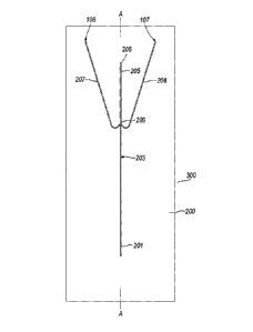
to 4. The device is denoted generally by reference numeral
300 and comprises a substrate 200 placed in intimate contact
with a cooling body 100. The substrate is, of
polytetrafluoroethylene and has formed within it a carrier
fluid conduit 201 for the carriage of a carrier fluid and a
functional fluid conduit 202 for the carriage of functional
fluid. The carrier fluid conduit 201 is approximately 0.3 mm
wide and 0.3mm deep. At the point at which the functional
fluid conduit 202 meets the carrier fluid conduit 201, the
functional fluid conduit 202 has an approximately circular
cross-section, with a diameter of about 50 to 150pm. The
CA 02728190 2010-12-15
WO 2010/004253 PCT/GB2009/001492
22
carrier fluid conduit 201 and the functional fluid conduit
202 meet at a junction region 210 (best seen in Figures 3
and 4). In use, droplets of functional fluid within a flow
of carrier fluid are formed immediately downstream of the
junction. A cooling conduit 203 extends downstream from the
junction region 210. The cooling conduit is about 0.3mm deep
and 0.3mm wide. In use, a segmented flow of droplets of
functional fluid carried in the carrier fluid passes from
the junction region 210 to the cooling conduit which is
cooled by the cooler body 100 as described below to form
cooled (typically solid) droplets. The droplets may, for
example, be frozen or may be in the form of a gel.
A desolvating conduit 205 extends downstream from the
cooling conduit to the device outlet 206, so that, in use,
the segmented flow of carrier fluid and cooled droplets
passes into the desolvating conduit. Two anti-solvent
conduits 207, 208 (each about 0.3mm deep and 0.3mm wide)
converge with the desolvating conduit so as to be able to
deliver anti-solvent to the desolvating conduit. This anti-
solvent causes solvent (but not the polymer solute) to leave
the cooled droplet, thus forming solid beads. Desolvation is
illustrated schematically in Fig. 6, in which an advancing
flow of carrier fluid carrying a substantially spherical
droplet of functional fluid (a) passes from an upstream
portion of cooling conduit 203 into desolvating conduit
portion 205, past converging anti-solvent conduits 207, 208.
Anti-solvent entering through conduits 207, 208 forms a
laminar flow in which the segmented flow is enclosed by the
anti-solvent flow. The cooled droplets (b) contact the
interface between carrier fluid and anti-solvent. Because
at least one component of the droplet. has an affinity for
(preferably is soluble in) the anti-solvent, there is a
CA 02728190 2010-12-15
WO 2010/004253 PCT/GB2009/001492
23
tendency for the cooled droplet (c) to pass into the anti-
solvent flow. As a result of the contact between cooled
droplet and antisolvent, desolvation takes place and the
polymer is precipitated. Because desolvation, in the method
of the invention, takes place at a rate somewhat limited by
the conditions under which desolvation takes place, the
precipitation of the polymer can typically occur such that a
matrix with a desirable morphology, narrow particle size
range and desirable porosity is obtained. Beads with a
relatively uniform morphology having a particle size within
a relatively narrow range offer the advantage that, when
used in drug delivery, they can provide improved drug
release characteristics as compared with beads having less
uniform morphology and particle size. Size and size
distribution of beads can affect a number of characteristics
of drug delivery, including the rate of release, the
effectiveness of targeting, suspension properties in a
disperson, and the syringability. Thus, the relatively
narrow size distribution of the particles obtainable in
accordance with the invention can, in a variety of
therapeutic products, favourably influence one or more of
those characteristics. Administration forms in which the
beads of the invention may be used include any in which the
delivery of a therapeutic agent in porous beads (also
referred to as microspheres) may be suitable. Such
administration forms may be for drugs for systemic use or
for locally targeted delivery and in particular, but not
exclusively, include injectable formulations and implants.
In the method of the present invention, the solvent is
generally soluble in (and miscible with) the anti-solvent.
The polymer solute is soluble in the solvent, but insoluble
in the anti-solvent.
CA 02728190 2010-12-15
WO 2010/004253 PCT/GB2009/001492
24
The desolvating conduit comprises an enlargement or
widening 209. Downstream of the enlargement the desolvating
conduit has a depth and width of approximately 0.5mm.
Carrier fluid is transferred to the carrier fluid
conduit through a carrier fluid inlet 103 formed in a
thermally conductive body 113. Functional fluid is
transferred to the functional fluid conduit through a
functional fluid inlet 102 formed in the thermally
conductive body 113. Anti-solvent is transferred to the
anti-solvent conduits 207, 208 through two anti-solvent
inlets 106, 107 formed in the cooler body 100. This
arrangement of inlet passages being formed through the
cooler body 100 and the thermally conductive body 113
facilitates the simple introduction of fluids to the
substrate 200.
The cooler body 100 is provided with a chilling channel
101 for the passage therethrough of chilling liquid. The
chilling liquid used in the present example is silicone oil.
The oil is cooled externally of the device and pumped into
the chilling channel 101. The passage of chilling liquid
through the chilling channel causes the cooler body to
become cold. Furthermore, the chilling liquid causes the
region of cooler body adjacent to the chilling liquid
conduit to become especially cold. In use, this region of
the cooler body is adjacent to the portion of the substrate
200 provided with the cooling conduit 203, thus causing any
droplets of functional fluid present in the cooling conduit
203 to freeze.
An insulating gap 109 is provided between the cooler
body 100 and the body of thermally conductive material 113.
The gap comprises insulating material (such as air).
CA 02728190 2010-12-15
WO 2010/004253 PCT/GB2009/001492
The choice of the temperature of the chilling fluid
should be selected to produce sufficiently cooled droplets
of the functional fluid whilst the carrier fluid remains
liquid. For example, the choice of the temperature of the
5 chilling fluid may be selected to produce frozen droplets of
the functional fluid.
The anti-solvent may be chilled, too ("chilled" meaning
being at a temperature less than ambient temperature).
The conduits in the substrate 200 are produced-by
10 removing material by micromilling using a Roland EGX-300
engraver or by laser drilling. The smaller conduits
(typically those having a diameter of 50-100 microns) are in
the form of apertures which may be produced using, for
example, laser drilling.
15 Those skilled in the art will realise that the size of
beads, produced by. the device and method of the present
invention depends on the flow rates of the carrier and
functional fluids and the sizes of the carrier fluid conduit
and the functional fluid conduit.
20 The surfaces in contact with the fluids should be of a
low energy and are typically formed by machining a substrate
of low energy material (e.g. polytetrafluoroethylene [PTFE,
for example, Teflon ]) or by machining a high energy
substrate and coating with a low energy material (e.g. by
25 vapour deposition).
Those skilled in the art will realise that alternative
coolers may be used. For example, Peltier coolers could be
used. Peltier coolers are widely available, for example,
from UWE Electronic GmbH, Unterhaching, Germany.
Those skilled in the art will realise that the junction
arrangement used above may be replaced by different junction
arrangements known to those skilled in the art. For example,
CA 02728190 2010-12-15
WO 2010/004253 PCT/GB2009/001492
26
EP1358931 discloses a Y-shaped junction and W00164332
discloses a T-shaped junction.
A cooling body 100' of a device similar to that of
Figs. 1 to 4 is shown in Fig. 5. The cooler body is
similarly constructed in most respects to the cooler body of
Figs. 1 to 4. In the cooler body of Fig. 5, however, there
are additionally provided a thermocouple 400 for measuring
temperature of the cooler in the region of the carrier fluid
conduit and the functional fluid conduit and a thermocouple
500 for measuring the temperature of the cooler body in the
region of the cooling conduit.
In the example of the embodiment of the device, the
polymer and active agent are mixed together and introduced
via one conduit into the device. It is possible to introduce
the active agent via a different conduit to the polymer, for
example, by providing an active fluid conduit which meets
the functional fluid conduit upstream of the junction
between the functional fluid conduit and the carrier fluid
conduit. Mixing within a droplet may be achieved using
velocity profile mixing as induced by segmented flow.
The desolvating conduit is shown in the present example
as being straight. The desolvating conduit may be convoluted
(for example, by being curved e.g. a spiral) to ensure that
the anti-solvent effect occurs over a long time scale.
The use of the device of Figures 1 to 3 in several
.examples of embodiments of a method in accordance with the
present invention will now be described.
General Method
Carrier fluid (silicone oil) is introduced, using a
pump, into the carrier fluid conduit 201 via carrier fluid
CA 02728190 2010-12-15
WO 2010/004253 PCT/GB2009/001492
27
inlet 103. The carrier fluid, for example, a 100cst silicone
oil (that is, a silicone oil having viscosity 100mPa.s at
20 C) passes through carrier fluid conduit 201, through the
cooling conduit 203 and out of the outlet 206 via the
desolvating conduit 205. Carrier fluid is permitted to flow
through the device for a short period of time. Chilling
fluid is then fed through the chilling conduit 101 of cooler
body 100. Anti-solvent (for example, an organic alcohol,
such as pentanol) is then introduced into the anti-solvent
conduits 207, 208 via anti-solvent inlets 106, 107. The
anti-solvent enters the desolvating conduit and moves to the
exit.
Once the cooler body has reached the desired
temperature, the functional fluid is introduced into the
functional fluid conduit 202 via functional fluid inlet 102.
The functional fluid may, for example, comprise a solution
of a biocompatible polymer and a pharmaceutically active
material. The flow rates of the functional fluid and carrier
fluid are such that there is formed a segmented flow of
functional fluid droplets in carrier fluid immediately
downstream of the junction region 210. Typically, the flow
rates of the carrier fluid and functional fluid are 1-
4ml/hour (often 2.5m1/hour) and 10-200microl/hour (often
50microl/hour), respectively. Both the carrier fluid and
functional fluid are stabilised at a predetermined
temperature (for example, at 20 C) before being introduced
into the device.
The droplets of functional fluid are sufficiently
chilled in the cooling conduit 203 that the solvent used in
the functional fluid is sufficiently cooled (preferably
solidified [for example, frozen, or formed into a gel]). The
droplets are typically sufficiently cooled within the first
CA 02728190 2010-12-15
WO 2010/004253 PCT/GB2009/001492
28
20-30mm length of the cooling conduit (this being especially
the case if the droplets are frozen, as opposed to formed
into a gel). The chilling liquid passing through the
chilling channel 101 is at -25 C. The segmented flow of
cooled droplets in carrier fluid is then transferred to the
desolvating conduit 205. The anti-solvent causes the solvent
to leave the cooled droplets, thus forming generally solid
beads, which leave the device via outlet 206. The flow rate
of anti-solvent is typically 1-4m1/hour (0.5-2m1/hour
through each of the anti-solvent conduits 207, 208), with
0.8-lml/hour being an often-used flow rate.
The temperature of the chilling fluid in the chilling
conduit 101 is variable. The temperature in the cooler body
100 in the region of the cooling conduit can be monitored,
for example by the thermocouple 500 as shown in Fig. 5. Four
illustrative cooling curves for the cooling body are shown
in Fig. 7 in which the device is cooled from ambient using
chilling fluid at -40 C, -25 C, -22.5 C or -20 C. The
temperature of the cooling body is measured by the
thermocouple 500 and reduces according to the respective
cooling curve in Fig. 7.
The device of the invention allows independent control
of temperature in the cooling conduit and upstream areas of
the device respectively, as illustrated with reference to
Fig. 8.
Illustrative temperature measurements are shown in Fig.
8 for thermocouples 400 and 500, during a heating/cooling
regime as described below.
Cooler unit initial temperature -40 C
Manifold initial temperature 17.9 C
Final manifold temperature -15.3 C
CA 02728190 2010-12-15
WO 2010/004253 PCT/GB2009/001492
29
Thermocouple 400 initial temperature=37 C
Thermocouple 400 final temperature=95 C
Zone A: Cooling curve- Started the cooling unit first
and recorded the temperatures of the manifold and cooler
unit at the same time. The temperature of the cooler unit
fluctuated at the beginning and stabilized after 17 minutes.
The temperature of the manifold sharply decreased over the
first 5 minutes then gradually reduced to a temperature of -
15.3 C.
Zone B: After cooling, the manifold was heated on the
left hand side. The temperature of the manifold began to
increase after 7 minutes.
Zone C: Cooling-heating-interaction curve. The
temperature of the manifold started to increase 7 min (Zone
B) after introducing heat and became stable after 47
minutes. The temperature of the manifold (right hand side)
increased by +3 C in total from start to finish.
The above regime shows that the temperature of the
upstream part of the device can be heated independently, and
with effective thermal insulation from, the cooling region.
The solute (the polymer) should not be significantly
soluble in the anti-solvent otherwise segments may collapse
on addition of the anti-solvent.
As already stated, the particles are typically
substantially spherical in shape. The mean diameter may be
ascertained by any suitable method. For example, the mean
diameter of the particles may be ascertained by viewing a
multiplicity of particles under an electron microscope,
measuring the diameter of a representative sample of, for
example, 15 particles, and ascertaining the mean diameter
therefrom.
CA 02728190 2010-12-15
WO 2010/004253 PCT/GB2009/001492
The following Examples illustrate the invention:
Example 1
5 The general methodology described above was used. The
functional fluid introduced into the functional fluid
conduit comprised a copolymer of lactide and glycolide,
(PLGA) dissolved in dimethyl sulfoxide (DMSO). The
concentration of the solution was 10% w/v. The copolymer
10 comprised 75% lactide units and 25% glycolide units, and had
a,MW of 66,000-107,000, available from Sigma Aldrich as
P1941 Poly(DL-lactide-co-glycolide).
The flow rates in the device were as follows:
Functional fluid flow rate: 0.05mL/h
15 Carrier fluid flow rate: 3mL/h
Anti-solvent fluid flow rate: 0.5mL/h
The anti-solvent flow rate indicated above relates to each
of two anti-solvent conduits; thus the combined anti-solvent
flow rate taking account of both anti-solvent feed was
20 1mL/h.
On entering the cooling part of the device, the
functional fluid formed frozen droplets. Desolvation of the
frozen droplets caused the formation of solid beads. The
carrier fluid comprised 100cst silicone oil. The anti-
25 solvent comprised ethanol
The beads so produced were spherical in shape. The size
of the spheres was measured using scanning electron and
light microscopy. Three batches of solid segments were made
using the same functional fluid. The size of 15 segments was
30 measured for each batch, yielding the mean diameters with
standard deviation values (S.D.) listed below:
CA 02728190 2010-12-15
WO 2010/004253 PCT/GB2009/001492
31
Batch 1 - 115.lpm, S.D. = 2.0 pm
Batch 2 - 121.4 pm, S.D. = 1.8 pm
Batch 3 - 108.9pm, S.D. = 1.8 pm
Example 2
The general methodology described above was used. The
functional fluid introduced into the functional fluid
'conduit comprised a copolymer of lactide and glycolide
(PLGA) dissolved in dimethyl sulfoxide (DMSO). The
concentration of the solution was 10% w/v. The copolymer
comprised 65% lactide units and 35% glycolide units, and had
a MW of 40,000-75,000, available from Sigma Aldrich as P2066
Poly(DL-lactide-co-glycolide)).
The flow rates were as used in Example 1.
On entering the cooling part of the device, the
functional fluid formed frozen droplets. Desolvation of the
frozen droplets caused the formation of solid beads. The
carrier fluid comprised 100cst silicone oil. The anti-
solvent comprised ethanol. Three batches made using the
same conditions.
The beads so produced were spherical in shape. The size
of the spheres was measured using scanning electron and
light microscopy. Three batches of solid segments were made
using the same functional fluid. The size of 15 segments was
measured for each batch, yielding the mean'diameters listed
below:
Batch 1 - 97.Opm, S.D. = 2.4pm
Batch 2 - 101.8pm, S.D. = 2.Opm
Batch 3 - 99.2pm, S.D. = 1.7pm
Example 3
CA 02728190 2010-12-15
WO 2010/004253 PCT/GB2009/001492
32
The general methodology described above was used. The
functional fluid introduced into the functional fluid
conduit comprised a copolymer of lactide and glycolide
(PLGA) dissolved in dimethyl sulfoxide (DMSO). The
concentration of the solution was 10% w/v. The copolymer
comprised 50% lactide units and 50% glycolide units, and had
a M, of 40,000-75,000, available from Sigma Aldrich as P2191
Poly(DL-lactide-co-glycolide)).
The flow rates were as used in Example 1.
The carrier fluid comprised 100cst silicone oil. The
anti-solvent comprised ethanol.
On entering the cooling part of the device, the
functional fluid formed frozen droplets. Desolvation of the
frozen droplets caused the formation of solid beads. The
beads so produced were spherical in shape. The size of the
spheres was measured using scanning electron microscopy.
Three batches of solid segments were made using the same
functional fluid. The size of 15 segments was measured for
each batch, yielding the mean diameters listed below:
Batch 1 - 95.6}im, S.D. = 1.3pm
Batch 2 - 97.lpm, S.D. = 1.8pm
Batch 3 - 98.lpm, S.D. = 1.7pm
In Examples 1, 2 and 3, no so-called "active"
ingredient was included in the functional fluid. It has been
found.that the incorporation of certain "active" ingredients
(such as leuprolide acetate) into the functional fluid does
not have an appreciable effect on the size of the segment
produced.
In the Examples 1 to 3 the method of the invention
enables there to be obtained polymer beads with a relatively
CA 02728190 2010-12-15
WO 2010/004253 PCT/GB2009/001492
33
consistent morphology and within a relatively narrow
particle size range. That can offer particular advantages
in drug delivery in terms of, for example, consistency
and/or predictability of the release of a therapeutic
substance contained within the beads.
Example 4
The entrapment of pharmaceutically active compound was
investigated to determine the effect of using different
anti-solvents.
The general methodology described above was used.
Leuprolide acetate dissolved in DMSO/PLGA mixture at between
1-5mg/ml of solution. The 50:50 lactide/glycolide polymer
P2191 used in Example 3 was used in this Example, at a
concentration of 10%w/v.
The flow rates were as used in Example 1. On entering
the cooling part of the device, the functional fluid formed
frozen droplets. Desolvation of the frozen droplets caused
the formation of solid beads.
Various anti-solvents were investigated to determine
the effect of the anti-solvent on the amount of active agent
(leuprolide acetate) retained in the beads. HPLC and/or NMR
were used to determine the amount of leuprolide acetate
retained.
Anti-solvent % active agent retained in solid
beads
Ethanol and pentanol 63
Pentanol 92
Heptanol (batch 1). 78
Octanol:ethanol (80:20) 76
Octanol:ethanol (90:10) 84
CA 02728190 2010-12-15
WO 2010/004253 PCT/GB2009/001492
34
Pentane 94
These data demonstrate that the choice of anti-solvent
is important. The anti-solvent should not be a good solvent
for the polymer. Furthermore, the anti-solvent should not be
a good solvent for the active' ingredient.
A further example of an embodiment of a device of the
present invention will now be described with reference to
Figures 9 and 10. The device is denoted generally by
reference numeral 600 and comprises a.substrate 800 placed
in intimate contact with a cooling body 700. The substrate
is of polytetrafluoroethylene and has formed within it two
carrier fluid conduits 601A, 601B for the carriage of a
carrier fluid and a.functional fluid conduit 602 for the'
carriage of functional fluid. The carrier fluid conduits
601A, 601B and the functional fluid conduit 602 are each
approximately square in cross-section and approximately lmm
wide and lmm deep. The carrier fluid conduits 601A, 602B and
the functional fluid conduit 602 meet at a junction region
610. In use, droplets of functional fluid within a flow of
carrier fluid are formed immediately downstream of the
junction. A cooling conduit 603 extends downstream from the
junction region 610. The cooling conduit is about 1.4mm deep
and 1.4mm wide. In use, a segmented flow of droplets of
functional fluid carried in the carrier fluid passes from
the junction region 610 to the cooling conduit which is
cooled by the cooler body 700 to form solid droplets.
A desolvating conduit 605 (having an approximately
square cross-section of width and depth of 1.7mm) extends
downstream from the cooling conduit to the device outlet
606, so that, in use, the segmented flow of carrier fluid
and solid droplets passes into the desolvating conduit. Two
CA 02728190 2010-12-15
WO 2010/004253 PCT/GB2009/001492
anti-solvent conduits 607, 608 (each about 0.7 deep and
0.7mm wide) converge with the desolvating conduit so,as to
be able to deliver anti-solvent to the desolvating conduit.
This anti-solvent causes solvent (but not the polymer
5 solute) to leave the solid droplet, thus forming solid
beads.
Desolvation occurs generally as described above in
relation to Figures l to 4.
Carrier fluid is transferred to the carrier fluid
10 conduits through carrier fluid inlets 703A, 703B formed in a
thermally conductive body 713. Functional fluid is
transferred to the functional fluid conduit through a
functional fluid inlet 702 formed in the thermally
conductive body 713. Anti-solvent is transferred to the
15 anti-solvent conduits 607, 608 through two anti-solvent
inlets 706, 707 formed-in the cooler body 700. This
arrangement of inlet passages being formed through the
cooler body 700 and the thermally conductive body 713
facilitates the simple introduction of fluids to the
20 substrate 800.
The cooler body 700 is provided with a chilling channel
701 for the passage therethrough of chilling liquid. The
chilling liquid used in the present example is silicone oil.
The oil is cooled externally of the device and pumped into
25 the chilling channel 701. The passage of chilling liquid
through the chilling channel causes the cooler body to
become cold. Furthermore, the chilling liquid causes the
region of cooler body adjacent to the chilling liquid
conduit to become especially cold. In use, this region of
30 the cooler body is adjacent to the portion of the substrate
800 provided with the cooling conduit 603, thus causing any
CA 02728190 2010-12-15
WO 2010/004253 PCT/GB2009/001492
36
droplets of functional fluid present in the cooling conduit
603 to solidify.
An insulating gap 709 is provided between the cooler
body 700 and the'body of thermally conductive material 713.
The gap comprises insulating material (such as air).
Example 5
The general methodology described above in relation to
Figures 9 and 10 was used. The functional fluid introduced
into the functional fluid conduit comprised,a 12% w/v
solution of poly(ethylene oxide) [181994 poly(ethylene
oxide), Sigma Aldrich, UK, MW - 200,000] in a 55:45 mixture
of dimethyl sulfoxide (DMSO) and water. The functional fluid
was introduced into the functional fluid conduit using a
heated syringe.
The carrier fluid comprised 100cst silicone oil.
The anti-solvent comprised 2-propanol.
The flow rates in the device were as follows:
Functional fluid flow rate: 1mL/h
Carrier fluid flow rate: 8mL/h
Anti-solvent fluid flow rate: 8mL/h
The anti-solvent flow rate indicated above relates to each
of two anti-solvent conduits; thus the combined anti-solvent
flow rate taking account of both anti-solvent feeds was
16mL/h.
The carrier fluid flow rate indicated above relates to each
of two carrier fluid conduits; thus the combined'carrier
fluid flow rate taking account of both carrier fluid feeds
was 16mL/h.
The droplets of the poly(ethylene oxide) solution cool
on entering the cooling portion of the device. Given that
CA 02728190 2010-12-15
WO 2010/004253 PCT/GB2009/001492
37.
the freezing temperature of the DMSO:water solvent is about
-40 C, it is not expected that the droplets would be frozen,
rather that the droplets either form a gel or are cooled to
form a very viscous liquid. The anti-solvent causes
desolvation of the cooled droplets, thus forming solid
beads. Even in the event that the cooled droplets were
liquid (as opposed to a gel), the droplets were of
sufficiently high viscosity that the beads formed from the
cooled droplets were of essentially the same shape as the
cooled droplets i.e. addition of the anti-solvent did not
cause the droplets to deform.
The solid beads were collected and suspended in 2-
propanol to ensure that the beads were substantially free of
solvent. The beads were removed from the suspension by
filtration and then dried.
It is anticipated that the step of suspending the beads
in bulk anti-solvent prior to drying is not necessary. In
the present case, this step was performed to ensure that the
beads were free of solvent.
The beads.so produced were spherical in shape. The size
of the spheres was measured using light microscopy. Two
batches of solid beads were made. The size of 30 segments
was measured for each batch, yielding the mean diameters
with standard deviation values (S.D.) listed below:
Batch 1 - 903 m, S.D. = 12 m
Batch 2 - 954 m, S.D. = llpm
This illustrates that the device and method of the present
invention may be used to produce beads of a generally
monodisperse nature.
Example 6
CA 02728190 2010-12-15
WO 2010/004253 PCT/GB2009/001492
38
The method of Example 5 was repeated, but with an antibody
(anti-streptavidin, labelled with fluorescein
isothiocyanate, [Abcam plc, Cambridge, UK]) incorporated
into the functional fluid.
The solid beads were assayed with stretavidin-bound
microtitre plates to demonstrate that the antibody held
within the beads retains its activity. Figure 11 shows the
fluorescent signal generated by the beads compared to
various other standards and controls. "Blank bead" refers to
.beads containing no antibody. The results labelled "50pmol",
"25pmol", "12.5pmol" and "6.25pmol" refer to the respective
concentrations of four control solutions of anti-
streptavidin. "Blank liquid" refers to a solution containing
no antibody.
It is apparent that the antibody held within the beads has
retained its activity.
Illustrative Example
Whilst this example does not fall within the scope of the
present invention because the method does not use a
microfluidic device to produce droplets, the example
illustrates the possibility of using the method and device
of the present invention to produce solid droplets
comprising a saccharide solute. It is anticipated that such
droplets may be of particular use in assays, since the
saccharide would be readily soluble in water or aqueous
solution.
Solutions of. 10% w/v of mannitol and dextran in water were
prepared. The solutions were then added dropwise to ethanol.
CA 02728190 2010-12-15
WO 2010/004253 PCT/GB2009/001492
39
The dextran solution produced amorphous particles in
ethanol. The amorphous particles readily dissolved in warm
water. The mannitol solution produced a microcrystalline
precipitate which dissolved in warm water.
It is anticipated that a solution comprising both mannitol
and dextran may be beneficial in that dextran appears to be
suitable for forming discrete particles and mannitol may
well be a suitable bulking agent. Furthermore, the mannitol
may give the beads a more manageable consistency.
Attempts were made to make solid beads from the polyol
solutions using the apparatus of Figures 1-4. The solutions
formed liquid droplets in a satisfactory manner, but these
droplets did not freeze. It is thought that further cooling
of the apparatus is required in order to freeze the
droplets. This may be achieved, for example, by improving
the cooling capability of the cooler.
A solution of 10% w/v of mannitol in dimethyl sulphoxide
(DMSO) was prepared. This was found to freeze at about 10 C.
It'is therefore anticipated that droplets made from this
solution would freeze using the apparatus of Figures 1 to 4,
and that solvent may be extracted from the frozen droplets
using an anti-solvent, such as ethanol.
As mentioned above, it is anticipated that the saccharide-
based droplets may be used in assays. In this case, it is
likely that it would be desirable for a bead to have a
diameter or largest dimension of about 0.5mm to 2mm. In this
case, it would be desirable to adapt the apparatus of
Figures 1 to 4 by having deeper and wider conduits
CA 02728190 2010-12-15
WO 2010/004253 PCT/GB2009/001492
(typically 2mm x 2mm). Furthermore, the flow rates used to.
produce larger beads would typically be greater than the
flow rates discussed above in Examples 1 to 4. For example,
the flow rate of the functional fluid through the functional
5 fluid conduit may typically be from about 1 to 20 ml/hour.
The flow rate of the carrier fluid may typically be from
about 5 to 30ml/hour.