Note: Descriptions are shown in the official language in which they were submitted.
CA 02728266 2014-06-12
WO 2009/155211
PCT/US2009/047154
PATIENT POSITIONING SYSTEM
FIELD OF THE INVENTION
This invention relates generally to holding devices and more particularly for
systems
for holding positioning, fixation and associated devices on a radiation
treatment couch or
other patient support structure.
BACKGROUND OF THE INVENTION
As will be appreciated by those skilled in the art, radiation therapy
treatment for
extracranial malignancy is trending toward fewer radiation fractions and
higher doses per
fraction over shorter periods of time. This is occurring because of
theoretical advantages in
the effect on tumor biology and both economic and social advantages related to
a shorter
treatment period and fewer trips to the clinic. This modality has been enabled
by tremendous
improvements in imaging with better tumor definition and visualization of
surrounding
structures combined with advances in linear accelerator (LINAC) beam targeting
and dose
painting technologies. The devices and methods of treatment required to
accomplish this are
collectively referred to as stereotactic body radiotherapy (SBRT). Previously,
stereotactic
radiotherapy has been applied mainly to brain tumors and often has been
reduced to a single,
high dose, precisely targeted treatment using an external frame that is bolted
to the skull, so
called stereotactic radiosurgery (SRS). Stereotaxy may be defined as the three
dimensional
spatial localization targeting of an object by using its known measured
relationship to an
adjacent set of objects. The objects in known relative position may be located
in an external
frame that is fixed in relation to the tumor as has historically been done for
SRS, or may be
any set of reference points having a known physical relationship to the target
that may be
available, so called "frameless stereotaxy".
SBRT is a new and rapidly developing area of cancer management. Consequently,
the devices and methods that support it are not yet optimized or widely
shared, and many
different paths have been taken.
Patient positioning is a prime example. Some investigators feel that extremely
precise and reproducible patient positioning is critical, whereas others
believe that frequent
re-localization of the target with imaging is more important. Some centers
have invested in
1
CA 02728266 2010-12-16
WO 2009/155211
PCT/US2009/047154
robotic LINACS that will move the beam to track a moving target, whereas
others have
invested in patient positioning and immobilization systems that restrict
movement of the
target tumor by restricting respiratory movement of the chest wall and/or
diaphragm. Several
device manufacturers have developed individual solutions for one camp or
another. All
parties are in agreement that keeping the patient as still as possible when
the treatment beam
is on, within some boundaries of comfort and the physiological processes that
are required to
sustain life, is highly desirable.
Patients undergoing SBRT typically are disposed on a treatment couch or table
associated with LINAC or other the radiation therapy apparatus. Various
couchtops and
overlays are commercially available for disposition on the treatment couch,
with the patient
being disposed on the couchtop/overlay. As is known an overlay is disposed on
top of the
cradle, existing support frame and/or spine of a CT, simulator or LINAC. For
SBRT
applications it is a common practice to position and fix a portion of the
patient so that
repeated treatment can be given to the patient. To that end, some indexing
system is
provided for mounting and positioning various patient positioning and/or
fixation devices on
the couchtop or overlay at predetermined positions with respect to the
couchtop/overlay.
Examples of such patient positioning/fixation devices are head and neck
positioning/fixation
devices, breast and thorax positioning/fixation devices, and hip and pelvic
region
positioning/fixation devices. Many of such devices, as well as other
miscellaneous
positioning aids, e.g., cushions, wedges, etc., for use on the treatment
couchtop/overlay are
available from the assignee of this invention, Civco Medical Solutions
(hereinafter
"CIVCO"), and are shown in its "Radiation Oncology Sourcebook" 2007.
The treatment couchtops/overlays available from CIVCO make use of an array of
equidistantly spaced indexing points running down the side of the
couchtop/overlay. A
two-pin LOKBARTM also sold by CIVCO is arranged to be connected to the
couchtop
overlay at any of the indexing points. The two-pin LOKBARTM is an elongated
bar that
includes two pins projecting upward from it to interface (be received in)
corresponding holes
on CIVCO' s line of patient positioning and fixation devices. To index a
particular
positioning/fixation device to the couchtop or overlay the LOKBARTM is
attached to the
couchtop or overlay via any of the multiple indexing points. The particular
patient
positioning/fixation device is then mounted on the LOKBARTM by disposing it on
the
LOK-BARTM so that the two-pins of the LOKBARTM are received within
corresponding
apertures in the positioning/fixation device. By indexing the patient
positioning/fixation
2
CA 02728266 2010-12-16
WO 2009/155211
PCT/US2009/047154
device(s) to the same indexing points for every radiation treatment one can be
assured of
increased target accuracy and patient throughput.
Other manufacturers also provide couchtops/overlays with indexing systems and
positioning/fixation devices to be used with such indexing systems. While
there are devices
that are commercially available to perform a specific method of patient
positioning and/or
immobilization and there are specific devices designed for various niche
approaches to
SBRT, what is missing is a general solution for immobilizing patients that is
sufficiently
versatile to have broad appeal to multiple centers doing SBRT. In short, what
is needed is an
integrated solution that allows the user to tailor the positioning and
immobilization methods
to suit the patient, their LINAC (or other therapy apparatus) and their
treatment plan.
The present invention addresses that need by providing a system for
reproducible
patient positioning and immobilization during SBRT. In particular, the system
makes use of
a modular design that allows a broad range of established positioning and
immobilization
techniques to be applied as needed. Patient comfort, setup time and patient
transportation are
optimized. The system basically comprises a portable platform (referred to as
a patient
support panel) having a pair of rails that enable full indexing of various
components used
during SBRT along its length. Those components also form part of the subject
system and
include modular multifunctional bridges and other positioning/fixation
components and
other components/accessories that may be positioned anywhere along the length
of the
platform to be used to position/fix the patient or provide any other function
desired during
SBRT treatment. The multifunctional bridges are particularly significant in
that they can be
positioned where needed to provide various types of immobilization, hold
instrumentation or
enable stereotactic frames or other positioning and localization devices to be
used.
Those bridges, the patient support panel and the other modular
accessories/component of the subject invention will be described in detail
later. Suffice it for
now to state that they allow the user to apply any of the full range of
positioning and
immobilization techniques that are in current use for SBRT. And, this is
accomplished with
the likelihood of greater comfort for the patient and ease of use for the
therapist. The patient
support panel accommodates standard stereotactic frames or frameless
approaches to
treatment. In addition, the patient support panel is designed to be
transportable with the
patient immobilized on it. Thus, workflow may be improved by allowing time
consuming
patient setup to be completed outside the expensive LINAC room and then have
the SBRT
platform precisely positioned on the standard LINAC treatment couch.
Alternatively, the
patient support panel with the patient immobilized on it could be transferred
to an imaging
3
CA 02728266 2014-06-12
WO 2009/155211
PCT/US2009/047154
device such as a CT or MR scanner to update targeting data prior to therapy
and then be
transferred to the LINAC couch without movement of the patient in relation to
the platform.
SUMMARY OF THE INVENTION
In accordance with one aspect of the invention there is provided a system for
positioning a patient on a treatment table, e.g., a LINAC couchtop, for some
type of therapy
that is to be repeated, e.g., SBRT, wherein the position of at least a portion
of the patient's
body to be treated is to be held in a predetermined fixed position, The system
comprises a
patient support panel and at least one positioning component, e.g., a bridge
member,
arranged to be releasably mounted on the patient support panel at a desired
position thereon
to hold the at least one portion of the patient's body at the desired
position. The patient
support panel comprises a generally planar member having a pair of
longitudinally
extending side rails. Each of the side rails has a series of longitudinally
spaced indexing
apertures. The apertures are aligned in pairs for releasably mounting a first
component, e.g.,
a cushion for supporting and holding the portion of the patient's body
thereon, between any
of the pairs at a desired longitudinal position along the patient support
panel via a
component mounting bar having at least one pin projecting upward therefrom for
receipt
within the first component. The at least one positioning component includes at
least one
clamp for releasable securement to a respective one of the side rails at any
longitudinal
position along the side rail.
In accordance with another aspect of this invention there is provided a device
for use
on a patient treatment table to enable some type of therapy that is to be
repeated to be
provided to a patient, wherein the position of at least a portion of the
patient's body to be
treated is to be held in a predetermined fixed position. The device basically
comprising a
frame arranged to be mounted on the treatment table. The frame includes a pair
of
longitudinally extending side rails, each of which has a series of
longitudinally spaced
indexing apertures. The apertures are aligned in pairs for releasably mounting
a first
component between any of the pairs of apertures at a desired longitudinal
position along the
device via a component mounting bar having a pair of pins projecting upward
therefrom for
receipt within the first component. The side rails are also arranged to
releasably mount at
least one positioning component thereon at any longitudinal position along the
side rails by
means of at least one clamping member associated with the at least one
positioning
component.
4
CA 02728266 2010-12-16
WO 2009/155211
PCT/US2009/047154
In accordance with still another aspect of this invention a system for
positioning a
patient on a table for an MRI imaging procedure is provided. That system
comprises a
patient support panel, a positioning component, and an MRI coil device. The
positioning
component is arranged to be releasably mounted on the patient support panel at
a desired
position with respect to the patient's body and is in the form of a bridge
member comprising
a pair of upstanding legs and a central section bridging the legs. The MRI
coil device is
arranged to be releasably mounted on the bridge member. Each of the legs of
the bridge
member includes a lower end having a connector arranged for releasable
securement to a
portion of the patient support panel at various longitudinal positions along
the patient
support panel. Each of the legs of the bridge member is adjustable in height
with respect to
the central section of the bridge member so that the MRI coil and frame member
can be
positioned and held close to a desired portion on the body of the patient.
DESCRIPTION OF THE DRAWING
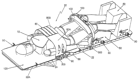
Fig. 1 is an isometric view of one exemplary embodiment of the system
constructed
in accordance with this invention showing a patient support panel and four
exemplary
positioning/fixation devices mounted thereon to position/fix the upper abdomen
and legs of
a patient's body for stereotactic radiation therapy or any other treatment
requiring repeated
immobilization of the particular portion(s) of patient's body;
Fig. 2 is an isometric view of the patient support panel of constructed in
accordance
with this invention shown with two patient positioning handles also
constructed in
accordance with this invention;
Fig. 2A is an enlarged isometric view of one of the two handles shown in Fig.
2;
Fig. 2B is an exploded isometric view of the components making up the handle
shown in Fig. 2A;
Fig. 3 is an enlarged isometric view of a portion of the patient support panel
shown
in Figs. 1 and 2;
Fig. 4 is an enlarged isometric view of the exemplary, pneumatically operated
positioning/fixation device for restricting respiratory excursion, like shown
in Fig. 1,
constructed in accordance with this invention;
Fig. 5 is a reduced, front elevation view of the positioning/fixation device
shown in
Fig. 4;
Fig. 6 is a front elevation view of a positioning/fixation device making use
of an
exemplary embodiment of a universal bridge of this invention shown mounted on
the patient
5
CA 02728266 2010-12-16
WO 2009/155211
PCT/US2009/047154
support panel having a vacuum operated conformable cushion mounted thereon on
which
the patient is disposed;
Fig. 7 is an enlarged isometric view of the universal bridge component making
up the
system of this invention and arranged for releasable securement to a patient
support panel
constructed in accordance with this invention;
Fig. 8 is an isometric view of a patient support panel constructed in
accordance with
this invention on which a conventional leg positioning cushion is mounted
utilizing a
locking bar constructed in accordance with this invention;
Fig. 9 is an isometric view of a portion of the patient support panel and the
locking
bar shown in Fig. 8, but without the leg positioning cushion;
Fig. 10 is an enlarged front elevation view of the locking bar shown in Fig.
9;
Fig. 11 is an enlarged isometric view of the leg positioning cushion shown in
Figs. 1
and 8;
Fig. 12 is an isometric view of another exemplary embodiment of a system
constructed in accordance with this invention for positioning/fixing the head
and shoulders a
patient on conventional radiation therapy table or couch for stereotactic
radiation therapy or
any other treatment requiring repeated immobilization of the particular
portion(s) of
patient's body;
Fig. 13 is an isometric view of one of the bridge members, i.e., the head
restraint
member, shown in Fig. 12;
Fig. 14 is a front elevation view of the bridge member shown in Fig. 13;
Fig. 15 is an isometric view of the other of the bridge members, i.e., a
shoulder
positioning/fixation device, shown in Fig. 12;
Fig. 16 is a front elevation view of the bridge member shown in Fig. 15;
Fig. 16A is a front isometric view of an alternative shoulder
positioning/fixation
device constructed in accordance with this invention;
Fig. 16B is a rear isometric view of the shoulder positioning/fixation device
shown in
Fig. 16A;
Fig. 17 is an isometric view of still another exemplary embodiment of a system
constructed in accordance with this invention showing a patient on the patient
support panel
with a fiducial targeting frame constructed in accordance with this invention
and with plural
handles also constructed in accordance with this invention for lifting the
entire assembly to
place it on a conventional radiation therapy table or couch;
Fig. 17A is an enlarged isometric view of each of the handles shown in Fig.
17;
6
CA 02728266 2010-12-16
WO 2009/155211
PCT/US2009/047154
Fig. 18 is an isometric view of the stereotactic fiducial frame shown in Fig.
17;
Fig. 19 is a front elevation view of the fiducial frame shown in Fig. 18;
Fig. 20 is an isometric view of a portion of an exemplary embodiment of a
mechanically operated positioning/fixation device for restricting respiratory
excursion
constructed in accordance with this invention;
Fig. 21 is an enlarged front elevation view of the system shown in Fig. 20;
Fig. 22 is an enlarged exploded isometric view of the clamp mechanism portion
of
the universal bridge component of Fig. 7 showing the details of that clamping
mechanism;
and
Fig. 23 is an enlarged exploded isometric view of the portion of the bridge
component shown in Fig. 22, but taken from a different direction;
Fig. 24 is an isometric view of a half rail frame constructed in accordance
with this
invention arranged to be directly mounted to any conventional couchtop via a
conventional
two pin lock bar registration system to enable the various modular
positioning/fixing
components and accessories of this invention to be mounted thereon;
Fig. 25 is an isometric view of two half sections like shown in Fig. 24
connected
together to form a full frame section in accordance with another embodiment of
the system
of this invention;
Fig. 26 is an isometric view of another bridge component, i.e., a MRI coil
positioning
device constructed in accordance with this invention;
Fig. 27 is a view, similar to Fig. 26, but showing an alternative embodiment
of the
MRI coil positioning device of this invention; and
Fig. 27A is an enlarged isometric view of the bottom portion of one of the
legs of the
MRI coil positioning device shown in Fig. 27.
DETAILED DESCRIPTION OF THE PREFERRED EMBODIMENT
Referring now to the various figures of the drawing wherein like reference
characters
refer to like parts, there is shown in Fig. 1 a system 20 for use on a
convention LINAC
couchtop or table (not shown) to repeatedly position/fix any portion of the
body of a patient
10 at any desired position(s) for SBRT or any other procedure requiring
repeated
immobilization of that portion(s) of patient's body. The system 20 basically
comprises a
patient support panel 22, and a plurality of modular components (to be
described later) that
are arranged to be releasably mounted on the patient support panel. For
example, in the
exemplary embodiment of Fig. 1 the modular components are a pneumatically
operated
respiratory restriction device 80, a bridge-supported leg restriction device
100, a
7
CA 02728266 2015-01-06
conventional knee support cushion 50, a conventional foot support cushion 52
and a
conventional torso support cushion or pad 120. Those components are merely
exemplary of
a myriad of components, conventional and otherwise (several of which will be
specifically
described herein), that can be mounted on the patient support panel for
repeated use in
SBRT.
It should be pointed out at this juncture that the patient support panel 22 of
the
system of this invention is also particularly suited for use in an invention
disclosed in a
United States Application Publication 20090307839 entitled
"Patient Transfer System For Use In Stereotactic Radiation Therapy", which is
assigned to
the same assignee as this invention.
That system will be referred to hereinafter as the "PTS" or "Patient
Transfer System" and basically comprises at least one low friction transfer
plate disposed on
the gurney and at least one similar low friction transfer plate disposed on
the treatment
couchtop. A plurality of bridging members are provided between the transfer
plates to bridge
the gap between the gurney and the treatment couchtop to facilitate the
sliding of the patient
support panel with the patient thereon from the gurney to the treatment
couchtop and vice
versa.
As best seen in Figs. 2, 3 and 9 the patient support panel basically comprises
a
generally planar member which is of sufficient size to support an adult
patient 10 in a prone
position like shown in Figs. 1, 12 and 17. In one preferred embodiment the
patient support
panel or platform is formed of a foam sandwich composite, e.g., FRP carbon or
aramid
fibers (e.g., KEVLARe), but can be formed of other strong non-metallic
materials, such as
fiberglass. The patient support panel 22 and has a pair of longitudinally
extending rails 22A
and 22B that enable full indexing of various components used during SBRT along
its length.
In particular, the longitudinal side edges of the patient support panel are of
a bulbous form in
cross section to define the rails 22A and 22B. A plurality of equidistantly
spaced (i.e., 7
cm), indexing apertures or holes 24 are provided along the length of each
rail. The apertures
24 are aligned transversely in pairs so that a two-pin registration or locking
bar 30 (Figs. 9
and 10) can be mounted on the patient support panel 22 between any pair of
apertures 24.
The two-pin locking bar 30 will be described in detail later. Suffice it for
now to state that it
constitutes a modification of the universally accepted multi-pin registration
system. In
particular, all standard/generic treatment couchtops, such as those available
from Medtec,
Sinmed, Varian Medical Systems, Inc., Elekta AB, and others use a pin system
to attach
positioning and immobilizing (fixation) devices or other components, e.g.,
vacuum bags,
8
CA 02728266 2010-12-16
WO 2009/155211
PCT/US2009/047154
knee rests, foot supports, head supports, etc., to the couchtop. Those
positioning/fixation
components are available from a number of vendors including CIVCO. The pin
systems are
in the form of a flat metal strip or bar (sometimes referred to a lock or
locking bar) having
registration pins, e.g., two pins (standard) or three pins (MR compatible),
projecting upward
to mount the positioning/fixation component thereon. The lock bar is arranged
to be
mounted on the couchtop and fixed to its surface at a desired indexed position
by means
(e.g., balls, sockets or clamps) mounted at the ends of the bar and which are
arranged to
engage cooperating means located at discrete index position on the couchtop.
The locking bar 30 of this invention includes releasably securable members,
e.g.,
expandable push pins (to be described later), to render it particularly suited
for releasable
mounting on the patient support panel 22 via any of the index positions
established by the
aligned pairs of apertures 24. Thus, by using a locking bar 30 one can readily
mount and
position any positioning/fixation component or any other accessory or
component on the
patient support panel at any of the discrete index positions therealong.
One of the significant features of the system 20 of this invention is that
various
positioning/fixation components and/or other accessories that are to be
mounted with the
patient on the treatment couchtop include clamping mechanisms (to be described
later)
which enable them to be repeatedly positioned at any longitudinal position
along the patient
support panel and not merely at the discrete indexing points established by
the pairs of
apertures 24. Thus, positioning/fixation components and/or accessories can be
mounted at
any of the discrete index positions via the locking bars 30, and/or at any
longitudinal
position along the patient support panel via the clamping mechanisms of such
components
(to be described later). To facilitate repeatable mounting of those components
on the rails
22A and 22B indexing indicia (not shown) are provided along the length of
those rails.
As should be appreciated by those skilled in the art from the discussion to
follow the
patient support panel 22 enables one to readily set up the patient outside the
treatment room
and then transport him/her in treatment position to the treatment couchtop.
Alternatively, if it
is necessary to image the patient in a CT scanner in treatment position and
transport him/her
to the treatment room in the same position, the patient support panel provides
a viable means
to accomplish that end. It can also be used simply by placement on the
treatment couch prior
to patient setup. In either case this does result in a "double layer" of
supporting tops, but that
is of minor concern.
In Figs. 24 and 25 there is shown a rail frame system 200 which will be
described in
detail later. Suffice it for now to state that the rail frame 200 can be used
on a conventional
9
CA 02728266 2010-12-16
WO 2009/155211
PCT/US2009/047154
couchtop to eliminate the use of the patient support panel 22 to hold the
various components
of the system 20 on the couchtop. Thus, the system 200 enables one to
effectively retrofit
existing treatment couchtops to be able to make use of the modular
positioning/fixing
components of this system. If the patient support panel 22 is to be used,
e.g., it will be used
to transport the patient and the associated positioning/fixing components in a
set-up state to
the treatment couchtop it can be mounted and indexed on the couchtop using the
two pin or
three pin lock bar systems. To that end, as can be seen in Figs. 2 and 3 the
patient support
panel has two groups of holes or apertures 28, the outer two apertures being
arranged to
accept the two pins of a two pin lock bar system, while all three apertures
are arranged to
accept the three pins of a three pin lock bar system.
As mentioned above, the rails of the patient support panel 22 (or the rails of
the rail
frames 200 to be described with reference to Figs 24 and 25) include side
rails having
indexing or receiving holes every 7 cm for the two pin (or three pin) systems
so that lock
bars may be positioned and re-positioned exactly the same as on any generic
treatment
couchtop. The spacing between the indexing holes 24 is thus one half of the
spacing
provided by conventional treatment couchtops to provide a finer degree of
longitudinal
position adjustability.
Although not shown in the drawings, the patient support panel 22 has a slight
recess
on its underside that provides clearance for the bar that fixes the pins on
the two pin or 3 pin
locating lock bars. This underside recess allows the patient support panel to
sit flush on a
standard couchtop surface. The patient support panel 22 also includes four cut-
outs, each
forming a respective hand-hold 32 for transporting the patient support panel.
The hand-holds
32 are disposed in pairs, located adjacent respective ends of the patient
support panel.
For some applications it may be desirable to provide a pair of handles for the
patient
lying on the patient support panel to grasp. To that end, the system 20
includes a pair of
patient handles 36 (Fig. 2), each of which is arranged to be releasably
secured to a respective
side rail 22A and 22B of the patient support panel at any longitudinal
position there along.
In order to accomplish that end, each handle includes a clamping mechanism for
releasable
securement to the respective side rails. Various types of clamping mechanisms
can be used
with this invention. One type constitutes an over-center levered latch
mechanism and is
shown in Figs. 2, 2A and 2B. Another type constitutes a cam tensioner clamping
mechanism and is shown best in Figs. 22 and 23. The details of those two clamp
mechanisms will be described later, suffice it for now to state that each
includes a pair of
jaws which are arranged to open with respect to each other to receive the
periphery of a
CA 02728266 2010-12-16
WO 2009/155211
PCT/US2009/047154
respective side rail 22A and 22B therebetween so that the clamp mechanism can
be slid to
any longitudinal position along that rail. Each of the jaws has a concave
surface
complementary to the profile of the rails 22A and 22B. Thus, once in the
desired position
the jaws can be closed to releasably secure the clamp mechanism at that
longitudinal
position.
The system for transporting the patient support panel 22 from gurney to
treatment
couchtop and from CT or MR scanner to gurney add to the value of patient
support panel
since it allows the time consuming step of accurate patient setup to be
completed outside the
treatment room or vault. High resolution imaging may be done for example in a
standard CT
scanner and with the patient "locked" into a known position using the various
cushions,
vacuum bags, bridges, etc. Then the patient can be smoothly transferred to the
gurney and
then to the treatment table saving a lot of valuable setup and imaging time in
the treatment
room. The transfer system for accomplishing that end is the heretofore
identified Patient
Transfer System and is simple, safe, smooth and accurate that relies on low
friction,
approximately level surfaces to work. Although low friction sliding surfaces
are used in
hospitals every day to transfer patients, the construction of the Patient
Transfer System is
unique in the use of the patient support panel beneath the patient, the method
and
components used to bridge the gaps between gurneys/tables on which the patient
resides,
and the methods and components used to accurately control the final position
of the patient
support panel, among other features.
The Patient Transfer System also uses the two pin (or three pin) locking bars
to
locate transfer plates of that system on the treatment or imaging surfaces,
while doing that in
turn allows precise positioning of the patient support panel on those
surfaces. The transfer
plates prevent damage to the undersurface of the patient support panel that
would otherwise
be caused by the protruding pin system when sliding the patient support panel
into position.
At the same time it allows the use of the highly accurate, universal two or
three pin locating
systems, and keeps the transfer plates applicable to all standard RT table
tops.
As shown in Fig. 17 specially designed handles 38 are provided to quickly and
easily
attach to the side rails 22A and 22B of the patient support panel for
facilitating the manual
lifting and transporting of the patient support panel with the patient
thereon. The handles 38
are best seen in Fig. 17A and basically comprise a cylindrical hand-grasp
member 40 having
a pair of yokes 42 at opposite ends of the member 40. A semi-circular bar 44
is connected to
the free end of each of the yokes and forms the upper jaw of a clamp
mechanism. The clamp
mechanism also includes a lower jaw 46, which is pivotably connected to the
hand-grasp
11
CA 02728266 2010-12-16
WO 2009/155211
PCT/US2009/047154
member 40. A spring-biased plunger 48 has a free end (not shown) which is
adapted to be
disposed within any one of the indexing apertures 24 in either of the side
rails 22A or 22B of
the patient support panel 22. With the plunger 48 in place in any of the
indexing apertures 24
the handle 38 is resistant to longitudinal displacement. Lifting upward on the
hand-grasp
member 40 has the effect of bringing the upper jaw downward toward the lower
jaw, thereby
tightly clamping the side rail 22A or 22B between those jaws. Thus, the handle
38 can be
used to readily and safely manually lift the patient support panel 22 with a
patient in any
situation.
Almost any variety of positioning and/or immobilizing (positioning/fixation)
equipment currently on the market that utilizes the pin localizing method can
be use on the
patient support panel 22 or on the rail frame 200. Thus, many types of head
frames or head
supports or other positioning/fixation components may be affixed to the table
top or rails as
desired. For example, as best seen in Figs. 1, 8 and 9 a conventional knee
support cushion
50, such as that sold by CIVCO under the trademark KNEE-LOK, and a
conventional foot
support cushion 52, such as that sold by CIVCO under the trademark FOOT-LOK,
may be
releasably attached to the side rails 22A and 22B of the patient support panel
22 by
respective two-pin locking bars 30. Each two-pin locking bar 30 is similar in
construction to
a conventional two-pin locking bar, like that sold by CIVCO under the
trademark LOK-
BAR, except that the ends of the bar include releasable fastening push pins
for releasable
engagement with the apertures in the patient support panel 22 or the apertures
in the rails (to
be described) of the rail frame 200. Thus, as best seen in Fig. 10, the
locking bar 30
basically comprises an elongated flat bar 60 having a respective push-pin end
piece 62 on
each of its ends. Each end piece 62 includes a generally T-shaped push pin 64
extending
therethrough. The push pins are of conventional construction sold by CIVCO
under the
trademark SAFE-T PINS. Each end piece includes a projecting free end portion
66 (Fig. 10)
that is arranged to be disposed within any of the indexing apertures 24 in the
rails 22A and
22B of the patient support panel 22 or in the corresponding apertures in the
rails of the rail
frame 200. Each free end 66 is arranged to expand (flare outward) when the T-
shaped head
of the pin is pressed/twisted, whereupon it frictionally engages the aperture
24 in which it is
located to hold the locking bar 30 in place at that indexing point. As is
conventional the
locking bar also includes a pair of registration pins 68 projecting upward
from it for receipt
within respective apertures or holes in the component to be mounted thereon.
For example,
as shown in Fig. 11 the knee cushion 50 includes a slot 70 with spaced holes
72 in its
undersurface to receive the lock bar 60 and the registration pins 68.
Stereotactic frames may
12
CA 02728266 2010-12-16
WO 2009/155211
PCT/US2009/047154
also be attached to the lock bar 30. In fact many components that may be
attached to
conventional two or three pin locking bars can be attached to the lock bars 30
of this
invention.
As will be appreciated from the discussion to follow many of the
positioning/fixation
devices/components constructed in accordance with this invention are arranged
to be
releasably mounted on the patient support panel 22 or on the rail frame 200 so
that a portion
extending above the prone patient will press down on a portion of the
patient's body to
restrict the movement of that portion of the patient's body or otherwise
immobilize it.
Examples of such devices are the heretofore identified devices/components 80
and 100, as
well as the devices/components shown in Figs. 7, 13 - 16, 20, 21. All of those
devices/components are typically to be used in combination with a pad or
cushion, like the
pad 120, disposed on the patient support panel 22. The pads/cushions serve to
provide a
conformable support surface for the patient to lie upon, such as shown in Fig.
1, and can
extend the full length of the patient support panel 22 or only a portion of
it, e.g., the torso-
length component 120. In any case, it is preferable that the cushions/pads be
adapted to
conform to the contours of the patient's body and to remain in that
configuration for the
duration of the SBRT. CIVCO sells vacuum actuated cushions/pads to accomplish
that end
under the trademark VAC-LOC. The VAC-LOCTM cushion/pad is a hollow flexible
member or bladder that is filled with a multitude of polystyrene beads to
create a rigid,
comfortable cradle around the patient when vacuum is drawn through a quick
release valve.
Referring now to Figs. 1, 4 and 5, the heretofore identified pneumatically
operated
respiratory restriction device 80 will now be described. This device is used
to minimize
diaphragmatic excursions which could interfere with radiation therapy directed
to the chest
or abdomen. By controlling the degree diaphragmatic excursion one can limit
the movement
of internal organs that move with the diaphragm. The device 80 is arranged to
be located at
any longitudinal position along the patient support panel 22 by virtue of its
clamping
mechanisms (to be described later). Thus, one can form fit the device 80 (or
any of the other
positioning/fixation components) precisely to the desired region of a
patient's anatomy to
achieve comfortable and very effective immobilization, i.e., create an
effective patient
immobilization sandwich comprising a top layer formed by the device 80 in
concert with the
vacuum cushion 120 disposed underneath the patient.
The device 80 basically comprises a belt-like member formed of a pair of
somewhat
flexible sheets 80A and 80B, each of which includes a clamp mechanism at its
lower end.
The belt like member 80 is arranged to be releasably mounted by those clamp
mechanisms
13
CA 02728266 2010-12-16
WO 2009/155211
PCT/US2009/047154
to the rails of the patient support panel 22 or to the rails of the rail frame
200 anywhere
along the axis of the patient using the index indicia on the rails. Each clamp
mechanism
shown in those figures is represented as being the heretofore mentioned over-
center levered
latch mechanism similar to that used on the patient handles shown in Figs. 2,
2A and 2B.
While such a clamp mechanism can be used for those applications, it is
preferable to use the
cam tensioner clamping mechanism like that shown in Figs. 22 and 23. In fact,
for most
applications that require a clamp mechanism to provide releasable securement
of the
positioning/fixation component, the cam tensioner clamp mechanism of Figs. 22
and 23 is
preferred.
The flexible sheets 80A and 80B of the belt member 80 are arranged so that
their free
ends can be overlapped by a desired amount respect to each other to
accommodate patients
of differing anatomic sizes, shapes and proportions. To that end, the flexible
sheets of the
belt-like member 80 include index marks for establishing an initial tightening
(overlap)
position. In order to hold the overlapped sheets in place with respect to each
other plural
rows of apertures or key holes 82 are provided in the free end portion of the
sheet 80B and a
row of upstanding buttons 84 is provided in the free end portion of the sheet
80A. The
buttons 84 are arranged for insertion into the key holes 82. In particular,
with the sheets
overlapped to the degree appropriate for a particular patient, a row of the
key holes 82 of the
sheet 80B will be aligned with the row of buttons 84 of the sheet 80A,
whereupon those
buttons can then be inserted into the aligned key holes to releasably secure
the overlapping
free ends of the sheets 80A and 80B together.
An inflatable bladder 86 (Fig. 5) is mounted on the underside of sheet 80A for
engagement with the epigastric area of the patient. The bladder 86 is arranged
to be inflated
by a hand pump (bulb) 88 and the pressure within the bladder measured by a
pressure gauge
90. Thus, one can pump the bladder up until it is at a desired pressure so
that the appropriate
degree of restriction of the patient's diaphragmatic excursions can be
established.
If mechanical respiratory restriction is desirable in lieu of the pneumatic
restriction
provided by the device 80, a bridge mounted mechanical positioning/fixation
device 110 can
be used with the patient support panel 22. The device 110 is shown in Figs. 20
and 21 and
basically comprises an adjustable pressure plate assembly 112 mounted on a
universal
bridge component 150. The pressure plate assembly basically comprises a plate
112A
mounted via a threaded screw 116 to a central portion of the universal bridge
component 150
for external compression in the epigastric area of the patient.
14
CA 02728266 2010-12-16
WO 2009/155211
PCT/US2009/047154
Before describing the details of the mechanical respiratory restriction device
110
further, a description of the universal bridge 150 is in order. It is called a
"universal" bridge
inasmuch as it can be used to mount a multitude of positioning/fixation
devices on it. The
universal bridge 150 is best seen in Fig. 7 and basically comprises a pair of
vertically
extending side legs 152 and an intermediate or central section 154. The lower
end of each of
the side legs 152 is arranged to mount a respective clamp mechanism thereon.
The clamp
mechanisms will be described later and are preferably the cam tensioner type
shown in Figs.
22 and 23. Suffice it for now to state that each includes an elongated post
156 which is
adapted to be slidably secured to the lower end portion of a respective side
leg 152 to adjust
the height of the bridge with respect to the patient support panel 22 on which
it will be
mounted. In particular, the lower end portion of each side leg 152 includes a
slot 158
through which a threaded thumb screw 160 extends. When the threaded thumb
screw is
loosened the post 156 of the clamp mechanism can be slid either up or down
with respect to
the side leg 152, thereby establishing the height of the bridge. To facilitate
the setting of the
height of the bridge indicia 162 is provided on each side leg.
The central section 154 of the bridge includes an opening 164 through which
the
threaded screw 116 of the restriction assembly 112 extends. The opening 164
can also be
used to accommodate any threaded member or other component mounting member to
adjustably support any component or assembly on the bridge. In addition, and
in the interest
of modularity, the central portion 154 of the bridge includes a pair of push
pins 64, like those
used with the locking bar 30. The push pins 64 serve to fixedly mount any of a
number of
components or assemblies onto the bridge. For example, the restriction
assembly 112
includes a housing 114A which is mounted on the underside of the central
section 154 of the
bridge via a pair of push pins 64. The housing 114A includes a slot in which a
thumb wheel
118 is disposed. The thumb wheel 118 includes a threaded hole through which
the threaded
screw 116 extends. The upper end of the threaded screw extends through a hole
(not shown)
in the housing 114A and through the hole 164 in the central section 154 of the
bridge. The
lower end of the threaded screw 116 is in the form of a pivotal joint mounting
the pressure
plate 112A thereon.
In use, the height of the bridge will initially be set by adjusting the height
of its legs
as described earlier. Once that has been accomplished the thumb wheel 118 can
be rotated to
establish the precise amount of pressure on the patient's diaphragm to
comfortably
immobilize the patient's abdomen. In particular, to mechanically adjust the
plate 112A with
CA 02728266 2010-12-16
WO 2009/155211
PCT/US2009/047154
respect to the bridge all that is required is to rotate the thumb wheel in the
desired rotational
direction to bring the plate either closer or further from the central section
of the bridge.
As mentioned earlier, the preferred clamping mechanisms for the various
components of the system 20 is the cam tensioner which is best seen in Figs.
22 and 23, but
also shown in Figs. 7, 16A, 16B, 26 and 27. Basically it comprises the
heretofore identified
post 156, a somewhat arcuate elongated body 166 terminating in its lower end
in an upper
jaw 168, a lower jaw 170, a rotary knob 172, a pivot pin 174, a biasing spring
176 and a
detent assembly (to be described later). As best seen in Fig. 23 the outside
surface of the
body 166 includes a cylindrical shaft or post 178 projecting outward. The
shaft 178 is
arranged to be received within a central opening 180 in a cam portion 184
projecting inward
from the inner surface of the knob 172. The lower jaw 170 is pivotably
connected to the
upper jaw 168 via the pivot pin 174 and is normally biased in the open
position by the spring
176. The cam portion 184 includes a surface engaging the upper portion of the
lower jaw
above its pivot axis. Thus, when the knob is rotated in the clockwise
direction the cam
surface presses downward on the top surface of the lower jaw to cause that jaw
to pivot
towards the upper jaw against the bias of the spring 176, thereby closing the
clamp
mechanism. In order to ensure that the jaws remain in the closed position the
heretofore
identified detent assembly is provided. That assembly basically comprises a
circular cap
member 178 including a star-like detent washer 178A and a plurality of
semicircular pits or
dimples 186 arranged in a circular array within a central recess in the knob
172. The
circular cap 178 with its star-like detent washer 178A projecting inward from
its inner
surface is arranged to be received within the central recess of the knob 172
and fixedly
secured to the shaft 180 by a threaded screw 190. The free end of the shaft
178 is of square
shape and is arranged to fit within a correspondingly shaped opening in the
detent washer
178A so that when the cap with its detent washer is secured to the shaft by
the screw 190 the
cap cannot rotate with respect to the shaft. The free end of each of the
prongs of the star-like
washer 178A includes a semispherical projection 192 of corresponding size and
shape to
each of the dimples or pits 186. Thus, when the knob 172 is rotated to a
position to cause
the jaws of the clamp mechanism to close the semispherical projections will be
seated in
respective ones of the dimples in the knob to deter the jaws from tending to
spring open.
When opening of the jaws is desired, all that is necessary is to rotate the
knob in the opposite
direction with sufficient force to overcome the holding force of the detent
mechanism,
whereupon the jaws will open and the bridge (or other member of which the
clamp
16
CA 02728266 2010-12-16
WO 2009/155211
PCT/US2009/047154
mechanism is a part) can be slid longitudinally on the rails of the patient
support panel to a
desired position or the bridge can be removed.
Referring now to Fig. 6, the details of the leg positioning/fixation device
100 as an
example of one use of the top cushion arrangement will now be described. That
device
basically comprises the heretofore identified universal bridge 150 on which a
conformable
vacuum operated cushion 102 is mounted. The cushion 102 is a rectangular
member of
similar construction to the cushion/pad 120 except that it is considerably
smaller in size.
The cushion 102 is mounted on the central section 154 of the universal bridge
150 via a pair
of push pins 64. The leg positioning/fixation bridge 100 is particularly
effective for
immobilizing a patient's legs when it is used with a leg positioning cushion
50 and a foot
positioning cushion 52 like shown in Fig. 1. However, it can be used alone or
with other
types of cushions, if desired. Moreover, it is not limited to holding down the
legs. Thus, it
can be used to fa the hips or shoulders of a patient.
Referring now to Figs. 12 ¨ 14, a skull positioning/fixation device 230 will
now be
described. That device basically comprises the heretofore identified universal
bridge 150 on
which an adjustable forehead engaging cushion assembly 232 is mounted. The
adjustable
forehead engaging cushion assembly 232 is somewhat similar in construction to
the
adjustable pressure plate assembly 112 of the mechanical respiratory
restricting device 110,
except for the substitution of a cushion 234 for the pressure plate 112A. In
particular, the
cushion 234 basically comprises closed-cell foam disposed about a rigid core.
The lower
end of the threaded screw 116 is fixedly connected to the core. The cushion is
arranged to
press down on the forehead to help immobilize the skull of the patient. To
that end, the
undersurface of the cushion is of a concave shape to readily accommodate the
forehead of
the patient. By twisting the thumb wheel 118 in either the counterclockwise or
clockwise
direction the cushion 234 can be brought closer or further away from the
forehead of the
patient. In use, the height of the device 230 will initially be set by
adjusting the height of its
legs as described earlier. Once that has been accomplished the thumb wheel 118
will be
rotated to bring the cushion 234 into engagement with the patient's forehead,
with the
precise amount of pressure to comfortably immobilize the skull.
Referring now to Figs. 12, 15 and 16, a shoulder positioning/fixation device
240 will
now be described. The device 240 is a dedicated unit that basically comprises
a pair of
vertically extending side legs 242 and an intermediate or central section 244.
The lower end
of each of the side legs 242 is arranged to mount a respective clamp mechanism
thereon. The
clamp mechanisms are preferably the cam tensioner type like disclosed
heretofore with
17
CA 02728266 2010-12-16
WO 2009/155211
PCT/US2009/047154
respect to Figs. 22 and 23, but may be of the over center latch type 300 as
will be described
later. Suffice it for now to state that in either case the clamping mechanism
includes an
elongated post 156 which is adapted to be slidably secured to the lower end
portion of a
respective side leg 242 of the device 240 to adjust the height of the device
with respect to the
patient support panel 22 on which it is mounted. In particular, the lower end
portion of each
side leg 242 includes a slot 246 through which a threaded screw 248 extends.
When the
threaded screw is loosened the post 156 of the clamp mechanism can be slid
either up or
down with respect to the side leg 242, thereby establishing the height of the
device. To
facilitate the setting of the height of the device indicia (not shown) may be
provided on its
side legs.
A pair of shoulder-engaging cushions 250 is mounted on respective end portions
of
the central section 244 by respective brackets 252. The spacing between the
shoulder-
engaging cushions is adjustable to accommodate patients of differing anatomic
sizes, shapes
and proportions. To that end, each bracket is mounted on a respective slot 254
in the central
section by means of an adjustable thumbscrew 256. When the thumbscrew is
loosened the
bracket with the cushion 250 mounted thereon can be slid to any transverse
position within
the associated slot 254, whereupon the thumbscrew can be tightened to fix the
cushion in
that transverse position.
As mentioned earlier, a preferred clamp mechanism for the various components
of
this invention is the cam tensioner shown in Figs. 22 and 23. A less
preferred, but still
viable, clamping mechanism is the over-the-center latch shown as part of the
patient
positioning handles 36 in Figs. 2A and 2B and designated by the reference
number 300. For
illustrative purposes the clamping mechanism 300 is shown as making up the
clamping
mechanisms of the devices 80, 100, 230 and 240, it being understood that the
screw
tensioner clamping mechanism shown in Figs. 22 and 23 is the preferred
mechanism for
those devices.
Referring now to Figs. 2A and 2B the details of the over-center latch clamping
mechanism 300 will now be described. That clamping mechanism basically
comprises an
upper jaw member 302, a lower jaw member 304, a latch handle 306, a first
pivot pin 308
and a second pivot pin 310. The latch handle is a lever-like member having an
upper
opening 312 and a lower opening 314. The lower jaw includes a bifurcated upper
portion
having axial aligned openings 316. The axially aligned openings 316 are
arranged to be
aligned with the upper opening 312 in the latch handle 306, with the pivot pin
310 extending
through those aligned openings to pivotably connect the lower jaw to the latch
handle. The
18
CA 02728266 2010-12-16
WO 2009/155211
PCT/US2009/047154
upper jaw is also bifurcated and includes axial aligned openings 318. The
axially aligned
openings 318 are arranged to be aligned with the lower opening 314 in the
latch handle 306,
with the pivot pin 308 extending through those aligned openings to pivotably
connect the
latch handle to the upper jaw. As will be appreciated by those skilled in the
art the foregoing
arrangement creates an over-center latch clamp, which when the latch handle is
pivoted
upward causes the jaws to move towards each other to a closed position like
shown in Fig.
2A.
The upper jaw has a concave surface of a shape complementary to the profile of
the
rails 22A and 22B. The lower jaw also has a concave surface of a shape
complementary to
the profile of the rails 22A and 22B. Thus, when the jaws are closed they will
tightly engage
the periphery of the rail portion between them to releasably secure the clamp
to that rail. In
order to release the clamping mechanism 300 all that is required is to pivot
the latch handle
downward 306, whereupon the jaws open to enable the device on which the
clamping
mechanism is mounted to be slid along the rail of the patient support panel to
a different
longitudinal position or to enable that device to be removed.
Referring now to Figs. 16 and 16B, an alternative shoulder
positioning/fixation
device 440 will now be described. The device 440 is a dedicated unit that
basically
comprises a pair of vertically extending side legs 442 and an intermediate or
central section
444. The lower end of each of the side legs 242 is arranged to mount a
respective clamp
mechanism thereon. The clamp mechanisms are preferably the cam tensioner type
like
disclosed heretofore with respect to Figs. 22 and 23, but may be of the over
center latch type
300 as described earlier. Suffice it for now to state that in either case the
clamping
mechanism includes an elongated post 156 which is adapted to be slidably
secured to the
lower end portion of a respective side leg 442 of the device 440 to adjust the
height of the
device with respect to the patient support panel 22 on which it is mounted. In
particular, the
lower end portion of each side leg 442 includes a slot 246 through which a
threaded thumb
screw 160 extends. When the threaded thumb screw is loosened the post 156 of
the clamp
mechanism can be slid either up or down with respect to the side leg 242,
thereby
establishing the height of the device 440. To facilitate the setting of the
height of the device
indicia 448 is provided on each of its side legs 242.
A pair of shoulder-engaging cushion assemblies 450A and 450B is mounted on the
central section 444 of the bridge device 440 by respective brackets 452. Each
assembly
includes a pair of cushions 454 and 456. The cushions 454 and 456 are secured
to respective
slightly curved plates 458 and 460. The plates 458 and 460 are pivotably
connected to each
19
CA 02728266 2010-12-16
WO 2009/155211
PCT/US2009/047154
other at a hinge joint 462 to enable one to adjust the angular relationship
between the plates
458 and 460 to accommodate the shoulders of patients of various sizes, shapes
and
proportions. To that end, the hinge joint 462 includes a tightenable handle
464 which when
tightened fixes the angle between the plates 458 and 460. Untightening the
handle 464
enables the angle between the plates (and the cushions mounted) thereon to be
set at another
angle for a different patient. The spacing between the cushion assemblies 450A
and 450B is
also adjustable to accommodate patients of differing anatomic sizes, shapes
and proportions.
To that end, each bracket is mounted on a respective slot 466 in the central
section 444 by
means of a threaded thumbscrew 468. When its thumbscrew 468 is loosened the
bracket
452 with the cushion assembly mounted thereon can be slid to any transverse
position within
the associated slot 466, whereupon the thumbscrew 468 can be tightened to fix
the cushion
assembly in that transverse position.
In Figs. 17 ¨ 19 there is shown a fiducial box or frame device 280 arranged to
be
mounted on the patient support panel 22 by means of push pins 64. The device
280
includes a frame 282 arranged for surrounding a portion of the patient on
which
geometrically oriented radio-opaque (visible on x-ray) or optical markers 284
are disposed.
The frame includes four legs, each of which terminates at its lower end in a
connector
member 286 constructed similar to the end members 62 of the locking bar 30. A
respective
push pin 64 extends through each connector to expand a projecting portion (not
shown) of
that connector within an associate indexing aperture 24 in the side rails of
the patient support
panel. The legs on each side of the frame 282 are spaced by an integer
multiple of the 7 cm
spacing between the indexing apertures 24 of the rails 22A and 22B so that the
fiducial
frame device 280 can be located at desired discrete longitudinal positions
along the patient
support panel as defined by the indexing apertures 24. When so mounted the
device 280
will serve to verify the precise location of the SBRT patient support panel 22
and the
patient/target tumor relative to the treatment beam isocenter.
As mentioned earlier, the rail sections 22A and 22B that are an integral part
of the
patient support panel, and which serve as the attachment area for many of the
SBRT
components can also be made in a free-form or stand-alone configuration that
can be
adapted to fit directly to a non-SBRT specific treatment couch (i.e., a
generic treatment
couch made by CIVCO, Varian, Elekta, or other vendors). Two exemplary
embodiments of
that stand-alone configuration 200 are shown in Figs. 24 and 25. Each
embodiment is in the
form of a frame 200 having a pair of side rails 222A and 222B. The rails 222A
and 222B
are constructed like the rails 22A and 22B and thus include the indexing
apertures 24 and
CA 02728266 2010-12-16
WO 2009/155211
PCT/US2009/047154
indexing indicia therealong. When the frame 200 is mounted on the conventional
couchtop
all of the other modular components of the system 20 of this invention can be
mounted
thereon. Thus, all the components designed specifically for the SBRT patient
support panel
22 can be used on a standard treatment couchtop without using the patient
support panel 22.
This is advantageous in that the rail frame embodiment 200 eliminates the
extra layer of the
SBRT patient support panel, while still allowing all the positioning and
immobilizing
functionality of the modular components except patient transfer (and set-up
outside the
treatment room). The rail frame embodiment 200 shown in Fig. 24 is a half
section, e.g., it
is approximately 43 inches long, that can be used by itself for some
applications, where full
coverage of the treatment couchtop is not necessary or desirable.
Alternatively, it can be
coupled to a like half section 200, as shown in Fig. 25, to cover the entire
treatment
couchtop. This allows the user great flexibility to use the system to suit the
user's specific
needs for treating any anatomic site.
The rail frame 200 basically comprises the heretofore identified rails 222A
and 222B
and a pair of transversely extending wide cross bars 202 and 204. Each of the
cross bars is
an elongated member which is fixedly secured at its respective ends via a
respective
connector 206 to a respective one of the side rails 222A and 222B to form an
integral unit.
As mentioned above each of the side rails 222A and 222B is of similar
construction to the
side rails 22A and 22B so that the side rails 222A and 222B can mount the
components of
the system 20 thereon in the same manner as the side rails 22A and 22B mount
those
components on the patient support panel 22. Thus, in the interest of brevity
the details of the
construction and operation of the side rails 222A and 222B for mounting the
component
thereon will not be reiterated.
The rail frame 200 is arranged to be mounted on the conventional treatment
couchtop
via a universal two pin registration locking bar system provided with the
couchtop. To that
end, each of the cross bars 202 and 204 includes a pair of apertures 208 to
accommodate the
two registration pins of the couchtop lock bar. In particular, the couchtop
lock bar (not
shown) is releasably secured to the couchtop (not shown) at the desired
position so that its
two registration pins extend upward for receipt in the apertures 208 of the
rail frame cross
bar 202 or 204. In the embodiment shown in Fig. 24, an exemplary two pin
registration lock
bar 30 is shown mounted on the rail frame at an exemplary position via a
respective pair of
apertures in the rails 222A and 222B to serve to mount any component or device
having
comparable registration apertures thereon. The lock bar 30 can be mounted at
any of the
index position established by the pairs of apertures along the length of the
rail frame 222A
21
CA 02728266 2010-12-16
WO 2009/155211
PCT/US2009/047154
and 222B. In the embodiment shown in Fig. 25, two exemplary two pin
registration lock
bars 30 are shown mounted on the rail frame at exemplary positions via a
respective pair of
apertures in the rails 222A and 222B.
The cross bars 202 and 204 of the rail frame 200 are located to maintain
consistent
14 mm spacing of the two pin indexing to existing couchtops. The rail frame's
components
can be formed of any suitable material, such as carbon fiber, fiberglass or
epoxy.
In Fig. 26 there is shown another positioning device 520 constructed in
accordance
with an aspect of this invention. The positioning device 520 is arranged to be
used in a
system for positioning a patient for an MRI imaging procedure of the head or
neck so that an
MRI surface coil assembly can be located at a precise desired position with
respect to the
head or neck of the patient. That system thus includes a patient support panel
on which the
patient is disposed for the MRI imaging procedure. The patient support panel
can be
constructed similarly to the patient support panel 22 described above or can
be any suitable
patient couchtop/overlay provided by various suppliers. The exemplary
embodiment of the
positioning device 520 shown in Fig. 26 is particularly suited for use with
the patient support
panel 22. The device 520 is in the form of a pair of bridge member 520A and
520B, each of
which comprises a pair of upstanding side legs 522 and a central section 524
bridging the
legs. The lower end of each of the side legs 522 is arranged to mount a
respective clamp
mechanism thereon. The clamp mechanisms are preferably the cam tensioner type
like
disclosed heretofore with respect to Figs. 22 and 23, but may be of the over
center latch type
300 if desired. Each clamp mechanism includes an elongated post 156 slidably
secured to
the lower end portion of a respective side leg 522 of the device 520 to adjust
the height of
the central (bridging) section 524 of the device with respect to the patient
support panel 22
on which it is mounted. Moreover, as described earlier, each clamp mechanism
includes the
a pair of jaws 168 and 170 which are arranged to grasp a respective portion of
the side rails
of the patient support panel 22 to enable the positioning device 520 to be
releasably located
at any longitudinal position along the patient support panel.
Any commercially available MRI surface coil assembly or device can be used
with
the bridge members 520A and 520B. Such devices are typically in the form of a
frame or
housing including one or more MRI coils (not shown) located therein. In the
exemplary
embodiment shown in Fig. 26 the MRI coil device is designated by the reference
number
526 and is the type sold by Siemens, but could be those sold by Philips,
Picker, GE
Healthcare or other vendors. The device 526 is arranged to be releasably
mounted by the
positioning member 520A and 520B. In particular, one portion of the coil
device 526 is
22
CA 02728266 2010-12-16
WO 2009/155211
PCT/US2009/047154
mounted on the central or bridging section 524 of the member 520A and another
portion of
that device is mounted on the central section 524 of the member 520B. The coil
device 526
is a generally flat, thin member that is somewhat conformable, i.e., it can be
bent slightly to
conform somewhat to the shape of the patient's head or neck at which it is to
be held. The
releasable securement of the frame 526 to the bridging members 520A and 520B
is
accomplished through the use of respective cooperating pairs of VELCRO hook
and loop
fasteners (not shown) disposed at the interface of the coil device 526 and the
underside of
the central sections 524 of members 520A and 520B. Other type of releasable
fastening
devices can be used in place of the VELCRO hook and loop fasteners.
Irrespective of the
type of releasable fastening means used, the use of releasable fastening means
enables
different types or sizes of MRI coil devices to be used with the bridge
members 520A and
520B.
As will be appreciated by those skilled in the art, since the bridge members
520A and
520B can be positioned at any longitudinal position along the patient support
panel 22 on
which the patient is disposed, and since the height of the central section 524
of each of those
members can be adjusted, the MRI coil device 526 can be positioned precisely
very close to
the desired portion the patient's head or neck.
In Fig. 27 there is shown an alternative embodiment 620 of an MRI coil
positioning
device. The device 620 is similar in construction to device 520, except that
the means for
releasably securing it to the patient support panel is different, i.e., it
doesn't make use of the
clamping mechanisms of the device 520. The reason for that variation is that
the device 620
is arranged for use with a patient support panel that is different from the
patient support
panel 22. In particular, the MRI coil positioning device 620 is arranged to be
used with a
Siemens couchtop/overlay. That couchtop/overlay includes a plurality of
mounting slots
extending along the couchtop/overlay adjacent its two longitudinally extending
sides. Each
of the mounting slots is arranged to receive a respective tab or projection of
a positioning
member to be releasably secured to the couchtop/overlay. Thus, as will be seen
and
described hereinafter the MM coil positioning device 620 makes use of tabs or
projections
from the side legs of its bridge members.
In the interest of brevity all of the details of the construction and use of
the MM coil
positioning device 620 will not be reiterated herein and those
features/components of it that
are common to the MRI coil positioning device 520 will be given the same
reference
numbers. Thus, as can be seen in Fig. 27 the device 620 is in the form of a
pair of bridge
member 620A and 620B, each of which comprises a pair of upstanding side legs
522 and a
23
CA 02728266 2010-12-16
WO 2009/155211
PCT/US2009/047154
central section 524 bridging those legs. The MRI coil device 526 is mounted on
the central
sections 524 of the bridge members 620A and 620B in a similar manner as
described with
respect to the MRI coil positioning device 520. As best seen in Fig. 27A, the
lower end of
each of the side legs 522 of each bridge member is in the form of an elongated
tab 622
projecting downward from a base block 624. Each projection 622 is shaped and
sized to fit
within any one of the mounting slots of the couchtop/overlay, with the
contiguous portion of
the base block engaging the top surface of the couchtop/overlay contiguous
with the
mounting slot. Accordingly, the bridge members 620A and 620B and the MRI coil
device
526 supported thereby can be positioned at any desired position along the
couchtop/overlay
where there are mounting slots suitable for disposing the MRI coil device
adjacent the head
or neck of the patient.
It should be pointed out at this juncture that the positioning devices 520 and
620 can,
if appropriate and desired, include only a single bridge member in lieu of the
pair of bridge
members used in those two disclosed embodiments. In fact, this invention
contemplates that
any number of bridge members can be used to support the MRI coil device,
depending upon
the size of the MRI coil device.
As should be appreciated from the foregoing many of the various devices of the
subject invention can be used to form fit to various regions of a patient's
anatomy and create
a top layer of a comfortable but controlling patient sandwich in concert with
a vacuum pad
underneath the patient and positioned and indexed on the SBRT patient support
panel.
Moreover, the modular design of the subject system provides complete
versatility of patient
positioning and patient immobilization. Those features and the ability to
transport the
patient on the patient support panel are keys to having a successful solution
and market
acceptance. Some or even most of the patient support panel accessories can be
"off the
shelf' commercial products that mount using standard locking bars, the
flexibility with
which these designs may be applied to accommodate almost any imaginable
combination of
methods for performance. Moreover, modular design approach supports complete
immobilization of any body part or combination of parts, yet also works well
with a
minimalist approach. The capability to set up patients outside the treatment
room is a
significant value for improving work flow efficiency. All of the components of
the system of
this invention can be produced from a variety of satisfactory materials that
are friendly to the
radiation and imaging environments.
24
CA 02728266 2010-12-16
WO 2009/155211
PCT/US2009/047154
Without further elaboration the foregoing will so fully illustrate our
invention that
others may, by applying current or future knowledge, adopt the same for use
under various
conditions of service.