Note: Descriptions are shown in the official language in which they were submitted.
CA 02728494 2011-01-17
COIL TUBING RIG AND CARRIER SYSTEM
FIELD OF THE INVENTION
The present invention relates to coil tubing rigs and, more particularly, a
coil tubing rig and transportation system for moving the coil tubing rig from
one
location to another location.
BACKGROUND OF THE INVENTION
Coil tubing rigs are commonly used in oil and gas applications, in drilling,
completion and workover activities. Furthermore, coil tubing rigs are commonly
used in the drilling of mining borehole, methane bed gas boreholes, water
wells,
and other earth boreholes.
With particular reference to the use of coil tubing rigs in operations
involving oil and gas wells, whether the activities are drilling, completion
or
workover, rig cost per day becomes an important factor. Coil tubing rigs have
gained great popularity, particularly in the drilling of the oil and gas wells
because
they are much faster on average than a conventional rig employing jointed
pipe.
Due to the high cost of operations involving drilling, completing and re-entry
work
in oil and gas wells, there is increased emphasis in reducing the number of
days
a rig is on a site to perform a given operation, e.g, drilling. Further, where
multiple wells are being drilled in a relatively localized geographical area,
fast
transport of the coil tubing rig from one site to another site becomes
important to
contain costs.
- 1 -
CA 02728494 2015-12-22
SUMMARY OF THE INVENTION
The system of the present invention comprises of a coil tubing rig and a
rig carrier. The carrier comprises a trailer frame and a dolly assembly
connected to the frame. The coil tubing rig is removably positionable on the
trailer frame. A plurality of hydraulic jacks each connected to the carrier
trailer
are activated to raise and lower that carrier trailer from a rig
loading/unloading
position to a rig operating position. In a rig loading/unloading position, a
front
end of the carrier trailer is substantially at ground level while the rear end
of the
carrier trailer is elevated.
A preferred embodiment of the invention includes a coil tubing system
having a wheeled carrier supporting both a coil tubing rig and a rig mast, a
trailer having a frame for selectively supporting the wheeled carrier in turn
supporting both the coil tubing rig and the rig mast thereon during transit
and
during rig operations, and a dolly assembly including a plurality of wheels
supporting the trailer.
A further embodiment of the invention includes a coil tubing system
having a wheeled carrier supporting both a coil tubing rig and a rig mast, and
a
coil tubing injector supported on the rig mast when in a rig operating
position, a
trailer having a frame for selectively supporting the wheeled carrier in turn
supporting both the coil tubing rig and the rig mast thereon during transit
and
during rig operations, and a dolly assembly including a plurality of wheels
supporting the trailer.
- 2 -
CA 02728494 2015-12-22
A further embodiment of the invention includes a method of using a coil
tubing system, the method including the steps of 1) providing a wheeled
carrier
supporting both a coil tubing rig and a rig mast, 2) providing a trailer
having a
frame for supporting the wheeled carrier in turn supporting both the coil
tubing
rig and the rig mast thereon during transit and during rig operations, and 3)
providing a dolly assembly including a plurality of wheels for supporting the
trailer.
These and further features and advantages of the present invention will
become apparent from the following detailed description, wherein reference is
made to the figures in the accompanying drawings.
- 2A -
CA 02728494 2011-01-17
BRIEF DESCRIPTION OF THE DRAWINGS
Figure 1 is a side elevation view showing a coil tubing rig and a rig carrier
as the coil tubing rig is loaded onto the rig carrier.
Figure 2 is a side elevation view similar to Figure 1 showing the coil tubing
rig positioned on the carrier and the rig mast raised.
Figure 3 is a side elevation view similar to Figure 1 showing the rig carrier
raised to the coil tubing rig operating position.
Figure 4 is a top view of the system shown in Figure 1.
Figure 5 is a side elevation view showing the rig carrier transported
without a rig.
Figure 6 is a front elevation view of the rig carrier shown in Figure 5.
- 3 -
CA 02728494 2011-01-17
-
DETAILED DESCRIPTION OF PREFERRED EMBODIMENTS
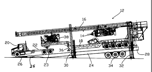
Referring to Figure 1, coil tubing rig 12 comprises a coil tubing injector 14,
and mast 16, and wheeled trailer 18. In other embodiments, a top drive may be
provided movable along the mast to conduct jointed pipe operations. Wheeled
trailer 18 is connected to a tractor 20 having a bed 22 and a connector, e.g.,
a
fifth wheel connector 23, to which the tongue of trailer 18 may be attached.
As
shown, coil tubing injector 14 is connected to a mast 16 which may be pivoted
from the transport position as shown in Figure 1 to a transverse position,
e.g.,
vertical, for conducting coil tubing operations. An engine and a hydraulic
power
source 38 may be positioned at the front end of trailer 18. The various
hydraulic
cylinders disclosed herein may thus receive power from source 38. A rig
carrier
trailer comprises a frame 24 and a dolly assembly 34, and is structurally
separate from the wheeled trailer 18.
As shown in Figure 1, frame 24 of the carrier trailer has a front or first end
25 and a rear or second end 28. As shown in Figure 1, front end 25 has been
lowered relative to the elevated rear end 28 such that front end 25 rests on
the
ground or other support surface. In this inclined position, rig 12 including
trailer
18 may be moved by tractor 20 up frame 24 to a desired position on frame 24.
Referring now to Figure 2, the system of Figure 1 is shown with the tractor
20 removed and the frame 24 substantially parallel to ground. At this stage,
cylinder 15 may be powered to raise mast 16 to a substantially vertical
position.
During this process, outriggers 30 each secured to the frame 24 are lowered so
that tractor 20 can be detached from the trailer 18. The support 36 near the
front
-4-
CA 02728494 2011-01-17
of the wheeled carder 18 is lowered to engage the frame 24 so that the wheels
19 and the lowered support 36 position the wheeled carrier in a substantially
level position on the carrier trailer. Once tractor 20 has been detached, it
can be
moved off frame 24 and the frame 24 can be raised to a substantially
horizontal
position by powering the outriggers 30, 32, as shown in Figure 2. To this end,
a
piston cylinder assembly 31 associated with each outrigger 30 and 32 is
extended to move the frame 24 from a position shown in Figure 1 to a
substantially horizontal position as shown in Figure 2. Once at the desired
position, the outrigger may be locked in place and fluid pressure relieved to
the
hydraulic cylinders.
As shown in Figure 3, the rig carrier 24 is elevated substantially above
ground level. A drop-down stairs 44 may be added to facilitate rig operations.
Coil tubing rig 12 may then commence operations. Mast 16 can be raised (or
may previously have been raised) to a substantially vertical position
generally in
line with the well bore. Drawworks 42 is hydraulically powered for conducting
rig
operations. It should be understood with reference to Figure 3 that a wellhead
assembly comprised of a BOP and any other suitable valves necessary for
drilling or re-entry work in an oil or gas well may be provided below the
position
of the raised trailer 18. In the Figure 3 position, the carrier trailer may be
15 feet
or more above ground level, such that the wheeled trailer 18 serves as an
elevated platform for rig personnel.
Once activities have been completed at the well site and it is desired to
transport the system to another site, hydraulic cylinders 31 and respective
- 5 -
CA 02728494 2011-01-17
outriggers 30 and 32 may be lowered to return to the Figure 2 positions.
Tractor
20 may be backed to a position where connector 23 may be connected to
wheeled trailer 18. Bed or gooseneck 22 may be a type typically used in the
interconnection of truck tractors to low-boy trailers. Examples of suitable
goosenecks are shown in U.S. Patent 4,390,192 and references cited therein.
Referring to Figure 4, a top view of the carrier trailer shown, depicting the
outriggers 30 and 32 each with hydraulic cylinder and a jack stand. Four sets
of
dollies are shown in Figure 2, and are discussed below with respect to Figures
5
and 6.
In Figure 5, the carrier trailer is folded along a center seam so that it has
substantially one-half of its width during normal use. This allows the carrier
trailer with no rig thereon to be more easily moved from one site to another
down
public roads. The carrier frame 24 thus consists of one side frame 52, and a
mirror image side frame 56. Frame 56 is pivotally connected to frame 52 so
that
the side frame 56 is folded onto the top of side frame 52. Various hinge
mechanism 60 are provided for this purpose. Two pairs of dollies 54 are
attached to side frame 53, while the side frame 56 also has two pairs of
dollies
58 attached thereto. A tongue 60 is used to interconnect the reduced width
carrier trailer to a tractor or other suitable power source. Figure 6 shows
the
assembly in Figure 5 from an end view. The side frame 56 and the dollies 58
are positioned above the side frame 52 and the dollies 54. A sleeve and pin
mechanism 62 may be used to maintain the frames in a side-by-side relationship
as shown in Figure 2 when in use to support a rig.
- 6 -
CA 02728494 2011-01-17
When the carrier frame is the loading/unloading position as shown in
Figure 1, the front end 25 of the frame 24 engages the ground level. A short
ramp 26 with a generally triangular cross-section is provided for smoothly
rolling
the rig and wheeled carrier 18 onto the carrier trailer 24. This triangular
ramp 26
may thus be used only for loading/unloading operations, and is not part of the
frame which is elevated to a rig operating position, as shown in Figure 3.
It should also be understood that the term "loading/unloading" is meant to
encompass either a rig loading operation onto the carrier trailer 24, or a rig
unloading operation from the carrier trailer 24. As disclosed herein, the rig
once
loaded onto the carrier frame may remain on the carrier frame and may be
transported in substantially the Figure 2 configuration from one well to
another
well, thereby saving valuable time which otherwise would be required to load
and
unload the rig and wheeled carrier from the components that elevate the rig.
A wheeled trailer as disclosed herein has a plurality of wheels, rollers, or
rotating tracks for moving the rig along the surface of the carrier frame 24.
The
term "wheeled carrier" as used herein is thus intended to encompass each of
these mechanisms for rolling the rig along the carrier frame 24.
The carrier frame as disclosed herein is a substantially rigid structure both
when loading a rig onto the carrier frame and when elevating the rig to the
Figure
3 operating position. This rigid structure of the carrier frame provides a
substantially planar upper surface for rolling the wheel carrier 18 onto the
carrier
trailer 24. Preferably the wheels for the wheeled trailer when in an operating
- 7 -
CA 02728494 2016-05-24
= -
position are positioned adjacent the rear portion of the carrier frame 24, and
are
directly above the dolly assembly 34 of the carrier frame.
Although specific embodiments of the invention have been described
herein in some detail, this has been done solely for the purposes of
explaining
the various aspects of the invention, and is not intended to limit the scope
of the
invention as defined in the claims which follow.
The scope of the claims
should not be limited by the preferred embodiments set forth in the
description, but should be given the broadest interpretation consistent with
the description as a whole.
- 8 -