Note: Descriptions are shown in the official language in which they were submitted.
CA 02728601 2011-01-18
=== ====
BP 279 CA
IE/HH/ak
Diehl BGT Defence GmbH & Co. KG, Alte NuBdorfer Str.
13, 88662 Oberlingen
Method and apparatus for imaging a surrounding area on
a detector device
The invention relates to a method for imaging a
surrounding area on a detector in which an optical
system produces an imaging beam path, and a panel,
which is arranged in the imaging beam path, shadows a
subarea of the image of the surrounding area on the
detector device.
Cameras for monitoring the surrounding area are
normally equipped with electrooptional sensors, for
example matrix detectors, on which the surrounding area
is imaged and, after electronic evaluation, is, if
required, displayed on a screen. If the image contains
a point radiation source or a radiation source which
has a small extent in comparison with the dimensions of
the field of view of the electrooptical sensor but is
strong, for example the sun, then this leads to
dazzling in the reproduced image, which interferes with
the image quality in an area around the imaged
radiation source. In the worst case, this even leads to
damage to the detector. Furthermore, when a strong
radiation source is present in the field of view of the
sensor, the extent of the scene dynamics that can be
detected is greatly restricted.
In order to avoid such effects, the electromagnetic
radiation which is incident on the detector is
prevented by varying the alignment of the detector, for
example by varying the alignment of the imaging optical
system. Another possibility is to close a shutter, thus
preventing radiation from passing through to the
CA 02728601 2014-01-17
,
, 26793-123
, =
- 2 -
detector, and therefore cOmpletely- protecting the
detector..
An object of some embodiments nf the invention is to
specify a method and an apparatus for imaging a surrounding
=
= area on a detector device, by means of which the
surrounding area can be monitored reliably even
when a strong radiation source is present.
According to some embodiments, the object relating to
the method is achieved by a method of the type mentioned
initially in which, according to the invention, the panel
is subdivided into a plurality of segments which can be
operated individually, and segments which are associated
= 15 = with the subarea are selected and operated, and are in
= this way heated, and the transmission of the selected
segments is reduced by the heating throughout the frequency
range in which the detector is sensitive - in particular
=
to excessively high illumination - and the selected segments
of the panel shadow the subarea of the image. As a result
of a selection of some of the segments of the panel, the
rest of the area of the panel at least substantially
retains its normal transmission. The subarea of the
image to be shadowed can therefore be selected. The
shadow can be placed in the image of the surrounding
= area such that a strong radiation source is shadowed
while, in contrast, the areas of the image located
outside the shadowing can still be evaluated, and the
corresponding parts of the surrounding area can be monitored.
=
The selection.of the segments to be heated, that.is to
say the area of the panel which is intended to be
heated in order to shadow the subarea, which is also
referred to in the following text as the area to be
heated, can be made by a control means which= controls
the_ corresponding circuits for heating the selected
segments. The control means= is prepared for this
purpose by one or more corresponding control programs
=
CA 02728601 2011-01-18
- 3 -
whose running - for example in conjunction with
suitable input signals, such as sensor signals -
results in such control. The corresponding control
program or programs provides the control means with the
capability to carry out the stated processes such that
the corresponding control is carried out when the
program is run. The control means is prepared to
control one, a number or all of the method steps which
are described in the following text, and in the
description of the figures.
The detector device expediently has at least one
detector, in particular a matrix detector which -
depending on the application - can carry out processing
simultaneously or exclusively in the spectral ranges
ultraviolet, visible light, near infrared, short-wave
infrared, medium-wave infrared and long-wave infrared.
The image expediently covers a certain angle range of
the surrounding area from the view of the optical
system, such that this section of the surrounding area
can be monitored. An angle range of 10 x 100 is
frequently covered by one image. The optical system may
be imaging optics comprising refractive, diffractive or
reflective elements, or any desired combination
thereof.
The transmission can be reduced by the heated area of
the panel more or less completely absorbing and/or
reflecting the radiation which is incident through the
optical system in at least that wavelength range in
which the detector is sensitive.
The panel advantageously contains thermochromic
material. Material such as this carries out a phase
change at a specific temperature, for example a
semiconductor-metal phase change, and in the process
fundamentally changes its optical characteristics, in
such a way that heating of the material can reduce the
transparency down to zero. Suitable materials are a
ak 02728601 2011-01-18
- 4 -
number of oxides of vanadium Vx0y, for example V02,
which carries out a semiconductor-metal change at 68 C,
V203, whose critical temperature is at -123 C, or non-
stoichiometric mixtures. The appropriate thermochromic
material is advantageously applied as a coating to a
panel support material, expediently with a thickness of
0.1 pm to 1 pm. Materials which are transparent in the
infrared range are suitable for use as the panel
support material, such as silicon, germanium, ZnSe or
ZnS. It is also expedient for the thermochromic coating
to be applied to a good heat carrier as an intermediate
layer, in order to allow heat which is introduced to be
dissipated quickly again, as a result of which the
layer is transparent again. A synthetic diamond layer,
in particular with a thickness between 10 pm and 50 pm,
is particularly suitable.
By way of example, the panel may be subdivided
corresponding to the pixels of the detector, such that
each pixel is associated with one segment. The segments
of the panel can be heated individually and separately
from one another. For this purpose, the segments can be
thermally isolated from one another, for example by a
web between two segments in each case. Each segment can
be provided with a heating element which is used to
heat only this segment. The heating element may have a
coating on a support material for the panel, which is
heated with the aid of electrical voltage. Metals or
alloys with titanium and/or platinum are particularly
suitable for this purpose. The coat may be in the form
of a frame around the segment to be heated or may be
arranged on two opposite sides on two edges of the
segment.
Advantageously, the selected segments are heated by
supplying electrical power. An electrical voltage can
be applied to heating elements for the segments, whose
resistance produces the heat. Electrical conductors are
CA 02728601 2011-01-18
- 5 -
expediently connected to each segment for this purpose,
and supply electrical power only to this segment.
Alternatively or additionally, one or more segments can
be heated by supplying optical power. Power can be
supplied through an optical conductor which is in each
case connected to one segment and supplies power only
to this segment. Illumination from an optical waveguide
across a distance through air is also possible, the
radiation from which is directed at one or more
segments - successively or simultaneously. The
radiation for supplying optical power can be introduced
behind an aperture stop of the optical system,
expediently behind the entire optical system, into the
beam path from the side, and can be directed at the
panel. It is expediently radiation which is directed at
the panel with the aid of optics, and whose frequency
is outside the sensitivity range of the detector
device. This radiation is advantageously produced by a
laser, although one or more LEDs is or are also
alternatively possible as the radiation source.
The method according to the invention is advantageously
developed such that dazzling or a dazzling object in an
image of the surrounding area is identified, and the
subarea of the image, and therefore also the heated
area or the area to be heated, is selected on the basis
of the position - and in particular additionally on the
basis of the extent - of the dazzling in the image.
This can be identified by image processing, for example
by an intensity measurement of the incident radiation,
in which case this intensity is classified as dazzling
if the intensity exceeds a limit value. Alternatively
or additionally, it is possible to select the area to
be heated as a function of a characteristic of a
dazzling object, for example its position, size and/or
shape, its dynamic and/or its beam strength.
CA 02728601 2011-01-18
- 6 -
The area to be heated is advantageously moved over the
image with any movement of a dazzling object, such that
the shadow correspondingly changes its position in the
image.
If the position of a dazzling object in space is known
in advance, then there is no need for image-processing
methods for selection of the area to be heated. For
example, the selection of the subarea can be determined
from the known position of the dazzling object in
space, and from the alignment of the optical system in
space. If required, the selection of the heated
segments can be matched to any movement, known in
advance, of the dazzling object in the field of view,
such that the dazzling object is always completely
shadowed.
Alternatively or additionally, it is advantageous for
the position of the area to be heated, that is to say
the segments to be selected, to be controlled on the
basis of a characteristic of a dazzling object or
dazzling by the dazzling object. By way of example,
although the sun is shadowed by a panel which moves
with it, it is possible, however, for the shadowing to
be incomplete because the optical system itself has
moved to a major extent, and for one edge of the sun to
emerge from the shadowing from time to time. If the
dazzling which results from this is identified as such,
and its position in the field of view is identified,
then the position of the area to be heated can be
readjusted by the closed-loop control system, and the
dazzling object can be completely or essentially
completely shadowed again in a very short time.
In order to allow a shadowed dazzling object to be
monitored precisely, it is advantageous for it still to
be visible through the shadowing. For this purpose, the
shadowing is not complete, such that a residual
transparency remains. In order to prevent damage to the
CA 02728601 2011-01-18
- 7 -
detector device, this residual transparency is
advantageously controlled such that the panel is heated
in an area to be heated such that it is opaque at the
frequencies at which the detector device is sensitive,
and the heating is reduced until a selected partial
transmission level is achieved. The transmission level
can be selected by image evaluation, by reducing the
heating, and therefore increasing the transmission
level, until the dazzling object is visible to a
predetermined extent.
In order to quickly reduce the transparency of the
panel in the selected area, it is advantageous for the
panel to be kept at a temperature which is close to the
critical temperature at which the panel changes its
transparency, for example carries out a phase change,
even before it is heated, at least in places. Suitable
separations from the critical temperature are of 1 C to
C. For this purpose, the panel can be preheated as
20 an entity or in a selected area, which can be made
dependent on a characteristic of a dazzling object and
is larger than the subarea, to be precise before the
transparency of the selected segments is reduced by
further heating. The preheating does not reduce the
transparency of the preheated part of the panel, or
reduces it only to a minor extent, for example by less
than 5% over the frequency range of the detector. The
heating is expediently carried out to a predetermined
panel temperature.
The closer the heating temperature is to the critical
temperature of the panel, the greater the extent to
which heating of the selected segments leads to the
heat that is introduced also heating edge areas outside
the area to be heated, thus reducing their
transparency. This results in a gradual reduction in
transparency around the area to be heated. The size of
the area outside the selected area whose transparency
is considerably reduced, at least by more than 50%, by
CA 02728601 2011-01-18
- 8 -
the heating is referred to in the following text as the
edge shadow area, and this can be set by the preheating
temperature.
This is advantageous in order to allow dazzling objects
with different movement dynamics to be masked out
effectively without extensive image interference. If a
dazzling object has low movement dynamics, that is to
say it is moving slowly over the field of view, a small
edge shadow area or no edge shadow area is sufficient,
since the heated area can be slaved to the dazzling
object in the field of view, corresponding to the slow
movement. In the case of high dynamics, it is possible
for the heated area not to follow the movement of the
dazzling object sufficiently quickly, that is to say
the segments to be heated cannot be changed quickly
enough, and the dazzling object, or its image, to leave
the shadow area. If there is no edge shadow area, the
full intensity of that part of the dazzling object
which emerges from the shadow strikes the detector
without being reduced.
Part of the dazzling object admittedly emerges from the
core shadow of the panel in an edge shadow area, but it
remains in the partial shadow of the edge shadow area
which gradually becomes more transparent outwards.
Depending on the size of the edge shadow area, the
emerging part is still greatly attenuated. The emerging
part of the dazzling object can be identified, and the
area to be heated can be appropriately readjusted, such
that the dazzling object is once again located in the
core shadow, and is completely screened. The preheating
is advantageously set as a function of a characteristic
of a dazzling object in the image. Control of the
preheating may comprise control of a characteristic
such as the size, shape and position of the area to be
preheated. Furthermore, a characteristic of an edge
shadow area may be selected and may be controlled by
the preheating. A desired characteristic of the edge
CA 02728601 2014-01-17
26793-123
- 9 -
shadow area can be determined corresponding to a
characteristic of a dazzling object, and preheating is
= controlled as a function of the characteristic.
Instead of or in addition to prior calculation of the
position of a dazzling object and the appropriate
positioning of the panel, a second detector can= be used
= to identify the position of a dazzling object, for
example by image-processing methods, and to position
the area to be heated such that radiation from the
dazzling object does not reach the first detector. For
this purpose, the dector device expediently has a first
and a second detector, and the beam path for the first
detector is interrupted, in particular completely
interrupted, such that no radiation any longer strikes
this first detector from outside the apparatus, the
subarea is selected with the aid of = the second
detector, for example by evaluating the image of the
second detector with the aid of image-processing
methods, and the dazzling object and its position in
the image are identified, the position of the area to
be heated is then defined, and the segments are heated,
and the beam path to the first detector is opened
again. The position of the dazzling object can be
tracked with the aid of the image obtained by the
second detector, and the area to be heated can be
positioned appropriately in front of the first
detector, such that the dazzling object is always
masked out of the image of the first detector.
The invention also relates to an apparatus'for imaging
=
a surrounding area on a detector device having an =
optical system for production of an imaging beam path,
and having a panel, which is arranged in the imaging
beam path, for shadowing a ubarea of the image of the
= surrounding area on the detector clevice.
= According to some embodiments, in order to achieve the
object relating to the apparatus, it is proposed
that the panel is subdivided
CA 02728601 2011-01-18
- 10 -
into a plurality of segments which can be operated
individually and each segment has a heating element,
and a control means is provided and is prepared to
select segments associated with the subarea and to
operate heating elements such that the selected
segments are heated, wherein the transmission of the
selected segments of the panel is reduced by the
heating throughout the frequency range in which the
detector is sensitive, and the selected segments shadow
the subarea of the image. A subarea to be shadowed can
in this way be shadowed quickly, as a result of which
it is possible to take precautions against image
interference or damage to the detector device. The
panel advantageously crosses through the entire beam
path, as a result of which it completely shadows the
detector when completely heated.
One embodiment of the invention provides for the
optical system to produce a beam path which is
telecentric on the image side, and in which the panel
is arranged. In the telecentric beam path, the
shadowing of the panel remains at least essentially of
the same size, irrespective of its position in the
field of view, thus making it possible to achieve
shadowing of homogeneous size even at the edges of the
field of view, when the illuminated area is positioned
there.
It is also advantageous for the detector device to have
at least two detectors, whose absolute and/or spectral
sensitivities are different to one another. The two
detectors are expediently directed at least essentially
at the same section of the surrounding area. In this
case, the first detector can be used to display the
image of the surrounding area, and the second can be
prepared for determining a characteristic of the
dazzling object.
CA 02728601 2014-01-17
26793-123
- 11 -
,
The panel is expediently at a distance of no more than 1/10 of
the focal length of a lens of the optical system which directs
the beam at the panel away from an image plane of the optical
system, in order to keep vignetting of the image low. It is
also advantageous for the panel to be moved in the direction of
the optical axis. This makes it possible to deliberately use
and vary vignetting of the image by means of the panel. This
invention detail can be used alternatively or additionally for
setting the edge shadow area by heating.
According to one embodiment of the invention, there is provided
a method for imaging a surrounding area on a detector of a
detector device in which an optical system produces an imaging
beam path, and a panel, which is arranged in the imaging beam
path, shadows a subarea of the image of the surrounding area,
in which a dazzling object is situated, on the detector,
wherein a) the panel is subdivided into a plurality of segments
which are operated individually, and segments which are
associated with the subarea are selected and operated, and are
heated, and the transmission of the selected segments is
reduced by the heating throughout the frequency range in which
the detector is sensitive, and the selected segments of the
panel shadow the subarea of the image, b) the heated segments
form a heated area and the area to be heated is selected on the
basis of the position of the dazzling object in the image, c)
the area to be heated is moved over the image with any movement
of the dazzling object and d) the panel is preheated in an area
which is larger than the subarea, before the transparency of
the selected segments is reduced by further heating, resulting
in a gradual reduction of transparency around the area to be
heated.
CA 02728601 2014-01-17
26793-123
- lla -
I
According to another embodiment of the invention, there is
provided an apparatus for imaging a surrounding area on a
detector of a detector device having an optical system for
production of an imaging beam path, and having a panel, which
is arranged in the imaging beam path, for shadowing a subarea
of an image of the surrounding area, in which a dazzling object
is situated, on the detector, a) the panel is subdivided into a
plurality of segments which can be operated individually and
each segment has a heating element, and b) a control means is
provided and is prepared to select segments associated with the
subarea and to operate heating elements such that the selected
segments are heated, wherein the transmission of the selected
segments of the panel is reduced by the heating throughout the
frequency range in which the detector is sensitive, and the
selected segments shadow the subarea of the image, to select on
the basis of the position of the dazzling object in the image
the heated area formed by the heated segments, to move the area
to be heated over the image with any movement of the dazzling
object by corresponding control and to preheat by corresponding
control of the heating elements of the panel in an area which
is larger than the subarea before the transparency of the
selected segments is reduced by further heating.
Further advantages will become evident from the following
description of the drawings, which illustrate exemplary
embodiments of the invention. The drawing and the description
contain numerous features in combination, which a person
skilled in the art will also expediently consider individually,
and combine to make further worthwhile combinations.
CA 02728601 2014-01-17
=
26793-123
- llb -
In the figures:
Figure 1 shows a schematic illustration of an apparatus for
imaging a surrounding area by means of a detector device which
has two different detectors,
Figure 2 shows an optical system on one of the detectors of the
detector device from Figure 1,
Figure 3 shows a panel, subdivided into individual segments, in
front of the detector from Figure 2,
Figure 4 shows a heated area of the panel from Figure 3, which
is surrounded by an edge shadow area, and
Figure 5 shows a control loop for the selection of segments of
the panel from Figure 4 to be heated.
CA 02728601 2011-01-18
- 12 -
Figure 1 shows an apparatus 2 for imaging a surrounding
area 4 on a detector device 6, which has two detectors
8, 10. The detectors 8, 10 are components of two
different cameras 12, 14, which both have a field of
view of 600 x 600 into the surrounding area 4, with
both cameras 12, 14 recording the same section of the
surrounding area 4. Both cameras 12, 14 are connected
to a control means 16, which is in the form of an
electronic data processing unit. The control means 16
has a computer program which is designed to control a
heating apparatus 18 (indicated merely symbolically in
Figure 1) for heating a panel 20 in front of the
detector 8, and for selection of a subarea of the image
on the detector 8 which is intended to be covered by
the panel 20.
The detector 8 is a microbolometer which is sensitive
in the infrared spectral range (long-wave infrared
between 8 pm and 12 pm) and is arranged in a vacuum
vessel. The detector 10 is likewise a matrix detector,
but is considerably less sensitive, although over a
wider spectral range, than the detector 8. While the
camera 12 is designed for imaging and monitoring the
surrounding area 4, the camera 14 is designed to
identify dazzling objects in the field of view of the
camera 12, in which case the position of the dazzling
object in the field of view of the camera 14, and
therefore in the field of view of the camera 12, is
determined with the aid of the control means 16.
Figure 2 shows an optical system 22 and that part of
the detector device 6 which is arranged in the camera
12. The optical system 22 has an objective with single-
stage optics with a field of view of 60 x 60 , and a
focal length of 18 mm. The f-number is 1. It comprises
two lenses 24, 26 composed of germanium, and the
aperture stop 28 is arranged immediately in front of
the first lens 24. The objective has a beam path which
is telecentric on the image side, that is to say the
. CA 02728601 2011-01-18
,
- 13 -
beam cones of the pixels on the detector 8 are
parallel.
That part of the detector device 6 which is located in
the camera 12 has, in addition to the detector 8, a
vacuum vessel with a detector window in front of the
detector 8, through which the beam path 32 of the
objective passes, and strikes the detector 8. The
distance between the panel 20 and the detector window
is 0.5 mm.
The panel 20 is arranged in the beam path 32 such that
it crosses through the entire beam path 32, and can
therefore block all the radiation that is incident
through the aperture stop 28 on the detector 8. It has
a highly thermally conductive intermediate layer which
is coated facing the optical system 22 with a
thermochromic layer 30 of vanadium dioxide, which is
indicated as a thick line in Figure 2. A support layer,
which is arranged opposite the thermochromic layer 30
and is used as a heat sink, is used to dissipate the
heat from the thermochromic layer 30, with this heat
being dissipated through the intermediate layer to the
heat sink. All three layers are transparent in the
infrared spectral range, in which the detector 8 is
sensitive, with the thermochromic layer 30 being opaque
for this spectral range above its critical temperature
of 68 C.
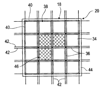
The panel 20 and the heating apparatus 18 are
illustrated in more detail in Figure 3. The panel is
subdivided into 256 x 256 segments 34, of which only 4
x 4 segments 34 are illustrated in Figure 3, for
clarity reasons. Each segment 34 is separated from the
others by webs 36 which somewhat thermally isolate the
segments 34 from one another. In order to heat the
segments 34, each of them is equipped with a heating
element 38 which has four heating units 40, which are
applied as a metallic layer to the thermochromic
CA 02728601 2011-01-18
- 14 -
material and surround a quarter of the segment 34. The
heating units 40 are each provided with two electrical
connections 42, which are connected to a voltage
generator, which is not illustrated and is operated by
the control means 16 such that all the heating units
40, and therefore the heating elements 38, can be
operated separately from one another. The heating units
40 are operated by applying a voltage to them, thus
heating them and transmitting the heat to the
thermochromic layer 30 of the segment 34. When the
thermochromic layer 30 is heated above the critical
temperature for the phase change, it first of all
gradually ceases to transmit light in the range between
8 pm and 12 pm, and ceases to transmit light completely
at a temperature above the critical temperature. The
entire panel 20 is surrounded by a heating means 44 in
the form of a frame which - operated by the control
means 16 - preheats the panel 20 as an entity to a
temperature that is predetermined by the control means
16.
The apparatus 2 is used as a monitoring system for
monitoring the surrounding area 4, and the panel 20 is
used for protection against an excessively high
illumination intensity on the detector 8, for example
from solar radiation. There is no need for the camera
14 in this example. The control means 16 calculates the
position of the sun in the image of the surrounding
area 4 on the detector 8, and determines a subarea of
the image which completely surrounds a dazzling object
50, in this example the sun. Those segments 34 which
completely shadow the subarea are determined on the
basis of the subarea or directly from the state of the
dazzling object 50 in the image. They form the heated
area, or area to be heated, 46. Three such segments 34
are illustrated in a shaded form in Figure 3, as an
example. The terms the selected segments 34, the heated
area 46 or area 46 to be heated of the panel and of the
subarea of the image which is shadowed or is to be
CA 02728601 2011-01-18
- 15 -
shadowed are used synonymously. The control means 16
now controls the heating elements 38 such that the
selected segments 34 are heated above the critical
temperature, and the dazzling object 50 is completely
masked out from the image of the surrounding area 4 on
the detector 8.
Furthermore, the control means 16, which has an image
processing unit, can detect a potential dazzling object
50, which is initially not dazzling, from the image of
the surrounding area 4. A dazzling object 50 may be an
aircraft or some other airborne vehicle, or a vehicle
or the like. The identification of a potential dazzling
object 50 can be determined by a characteristic of the
dazzling object 50, for example a shape or some other
characteristic of the appearance, an emission
characteristic, for example that of an engine, and/or
movement dynamics. It is also possible to identify the
potential dazzling object 50 by radar, which is
connected for data transmission purposes to the control
means 16. The subarea to be shadowed and the segments
34 of the panel 20 for masking out the dazzling object
50 can be chosen as appropriate from the identified
position of the potential dazzling object in space or
in the field of view, and the heating of the segments
34 can be started such that the subarea around the
dazzling object 50 is shadowed before it produces
dazzling.
First of all, the heating is carried out such that the
selected segments 34 of the panel 20 become completely
opaque, and therefore do not transmit light in the
sensitivity range of the detector 8. The area 46 to be
heated for this purpose is illustrated in Figure 3 on
the basis of three shadowing segments 34, and in Figure
4 on the basis of an example of a circle, although any
other shapes for the area 46 to be heated are possible.
The power introduced, and therefore the heating, are
then reduced to such an extent that the temperature of
CA 02728601 2011-01-18
- 16 -
the panel 20 in the area 46 falls to the critical
temperature, such that the thermochromic material
becomes transparent again. The dazzling object 50 is
once again initially visible in the image, and can be
identified and tracked on the basis of image
processing. The heating of the area 46 is now
controlled on the basis of a characteristic of the
dazzling object 50 in the image. Open-loop or closed-
loop control on the basis of one characteristic of the
dazzling object 50 is generally advantageous. The power
is expediently adjusted such that the dazzling object
50 is still identifiable, but its radiation does not
interfere with the image. Other characteristics, such
as radiation continuity of the dazzling object 50, can
also be used for open-loop or closed-loop control of
the power introduced. In general terms, the open-loop
or closed-loop control of the power introduced is
carried out from results of image evaluation of the
image of the detector device 6.
Furthermore, there is an image processing program
within the control means 16, which evaluates an
illumination intensity of each pixel of the matrix
detector 8 and/or of the matrix detector 10 in the
camera 14. If the intensity in at least one pixel
exceeds a limit value, then a masking-out process is
started with the aid of a program or program part which
is run by the control means 16. For example, if the
radiation intensity in the dazzled pixel is above the
first limit value but below a second limit value, such
that the radiation is not classified as a risk of
damage to the detector 8, despite interfering with the
image, the position of the dazzled pixel can be
determined with the aid of the detector 8, and the
shadowing can be left. If the dazzling object 50
emerges from the shadowed area in the image, then
pixels at the edge of the shadow are dazzled, as a
result of which their intensity rises above the limit
value. This is registered by the control means 16, and
,
CA 02728601 2011-01-18
- 17 -
the position of the shadowing is controlled in
accordance with the measured radiation intensities such
that the shadowing is moved over the dazzled pixels.
The controlled variable is a radiation intensity
measured on the detector 8 or detector 10.
If a measured intensity exceeds a second limit value,
then a shutter 52 in the first camera 12 is closed, as
a result of which the beam path 32 is completely
interrupted, or radiation no longer strikes the
aperture stop 28. It is therefore no longer possible to
monitor the surrounding area with the aid of the camera
12. Instead of this, coarser monitoring of the
surrounding area 4 can be carried out with the aid of
the camera 14, whose purpose is now to detect the
position of the dazzling object in the field of view or
in the image. This is carried out by an intensity
measurement of the radiation on the pixels of the
detector 10 or its signal strength, with the aid of the
control means 16. As soon as the position of the
dazzling object 50 is determined in the field of view
or in the image, the relevant image area and a
predetermined surrounding area, together the subarea,
are shadowed by it. The shutter 52 is then opened again
and monitoring of the surrounding area is continued,
with the dazzling object 50 being completely masked out
by the shadowing in the image. The position of the
shadowing in the image is continuously readjusted with
the aid of the radiation intensities measured at the
detector 10, from which the position of the dazzling
object 50 in the image is continuously monitored. It
is, of course, also possible to track the position of a
dazzling object 50 with the aid of the detector 8, when
the radiation intensity of the dazzling object 50 is
only between the two limit values. It is likewise
possible to dispense with the camera 14, and to carry
out the intensity evaluation and/or position
measurement of the dazzling object only with the aid of
the detector 8.
CA 02728601 2011-01-18
- 18 -
The size and shape of the heated area 46 and therefore
the shadow on the detector 8 may be selected as
required and, in the extreme, may also cover the entire
image. The greater the shadowing, the more power is
introduced into the panel 20. This power can be applied
soley by the heating elements 38. In cold ambient
temperatures and/or for large areas 46, it is
worthwhile introducing a portion of the power through
the heating means 44, by means of which the panel 20 is
preheated. The temperature of the panel 20 is detected
by a sensor which is connected to the control means 16
and scans the entire area of the panel 20. The
preheating power may be made dependent on the ambient
temperature, the temperature of the panel 20 and/or the
size of the area 46 to be heated.
A size of the area 46 to be heated, and therefore of a
shadow in the image, can be matched to a
characteristic, for example a size, of an identified
dazzling object 50. In this case, attention can be paid
to selecting the size of the area 46 to be heated such
that there is always a fixed distance between the edge
of the dazzling object 50 and the edge of the
shadowing. This distance may be influenced by a number
of factors. One factor may be a radiation intensity of
the dazzling object 50 per unit area on the detector 8.
Movement dynamics of the dazzling object 50 in the
image can also be used as an open-loop or closed-loop
controlled variable for setting the size of the
shadowing, and therefore of the subarea. If the
dazzling object 50 has low movement dynamics, that is
to say it is moving at slow speed in the image, it is
sufficient to leave the shadowing small, since the risk
of the dazzling object 50 emerging without being
noticed from the shadowing in the image is low. In the
case of high movement dynamics, it is worthwhile to set
the shadowing to be large, such that the dazzling
object 50 remains shadowed even in the case of fast and
CA 02728601 2011-01-18
- 19 -
unexpected movements. In general terms, the size of the
area 46 and therefore of the shadowing is set as a
function of a characteristic, in particular of the
movement dynamics of the dazzling object 50 in the
image.
Figure 4 shows an edge shadow area 54 which is made
usable around the heated area 46. The size of the edge
shadow area 54 may be set by the preheating temperature
of the panel 20 and, alternatively or additionally, by
the heating power of the heating elements 38 per unit
area. The higher the preheating temperature of the
panel 20 and/or the heating power of the heating
elements 38 is, the larger is the edge shadow area 54
with respect to the width of the edge shadow area 54
which results in Figure 4 from the illuminated area 46,
which forms a core shadow with a first diameter 56, and
the edge shadow area 54, which forms a partial shadow
with a larger diameter 58. Half of the difference
between the two diameters 56 and 58, and therefore the
width and/or size of the edge shadow area 54, can thus
be set.
A similar effect can be achieved by vignetting of the
image by the shadowing, if this is not located on an
image plane of the optical system 22. The further the
panel 20 is away from the image plane, the greater is
the vignetting. The vignetting can be adjusted by
moving the panel 20 in the beam path 32 in the
direction of the optical axis 60. The further the panel
20 is away from the image plane, the greater is the
vignetting, and the ratio of the large diameter 58 to
the small diameter 56, even without an edge shadow area
54. The movement of the panel 20 parallel to the
optical axis 60 is likewise controlled by the control
means 16, in which case closed-loop control is also
feasible.
CA 02728601 2011-01-18
- 20 -
The vignetting and/or the edge shadow area 54 are/is
adjusted by the control means 16 as a function of a
characteristic of the dazzling object 50.
The characteristic may be movement dynamics of the
dazzling object 50, a speed of the dazzling object 50
in the image, a size and/or a radiation intensity of
the dazzling object 50.
An open or closed control loop for selection of the
shadowing segments 34 and for setting the heated area
46 is illustrated in Figure 5. The detector device 6 is
part of a seeker head of a missile, and contains the
panel 20. This is driven by control electronics 62 with
control data for shadowing the detector 8. The detector
device 6 supplies sensor data to signal processing 64,
which uses image processing to identify the dazzling
object 50 and its position in the image. The
apparatus's own position data is determined with the
aid of an inertial measurement unit 66, including the
alignment of the cameras 12, 14 in the surrounding area
4. The control means determines the position data of
the dazzling object 50 from its own position data and
the position of the dazzling object in the image. This
or directly the data relating to the position of the
dazzling object 50 in the image is used to produce the
control data for the panel 20 and the heating apparatus
18. The sensor data is used to continuously correct the
control data, such that the dazzling object 50 is
always completely or partially shadowed. The dazzling
in the image or the position of the dazzling object 50
in the image within the shadowing can in this case be
used as a controlled variable.
CA 02728601 2011-01-18
- 21 -
List of reference symbols
2 Apparatus
4 Surrounding area
6 Detector device
8 Detector
Detector
12 Camera
14 Camera
16 Control means
18 Heating apparatus
Panel
22 Optical system
24 Lens
26 Lens
28 Aperture stop
Layer
32 Beam path
34 Segment
36 Web
38 Heating element
Heating unit
42 Connection
44 Heating means
46 Area
Dazzling object
52 Shutter
54 Edge shadow area
56 Diameter
58 Diameter
Optical axis
62 Control electronics
64 Signal processing
66 Inertial measurement unit