Note: Descriptions are shown in the official language in which they were submitted.
CA 02728661 2010-12-20
WO 2010/030476 PCT/US2009/054380
CE17682DE
MAIN SEAL SYSTEM AND METHOD
FOR USE IN AN ELECTRONIC DEVICE
Field of the Invention
[0001] This invention relates to mechanical seals, and more particularly, to
sympathetic seals used in electronic devices.
Background of the Invention
[0002] Seals used to protect components used in portable electronic devices
are
commonly used in order to protect an inner portion of the device from water,
moisture
and other outside elements. One type of seal most often used in these devices
is a
compression-type seal. Compression seals are probably the oldest and most
common
seal type where sealing is accomplished by tightening the seal along its edge
such that
it is compressed onto another mating surface. Compression seals, or gland
seals, are
used in such applications as compression packing, gaskets, and fluid sealing
type
devices. Compression packing seals often work to seal any number of fluids,
including water, acids, solvents, gases, oil, and other chemicals, in a range
of varying
conditions, such as temperature and pressure. Thus, compression seals are a
broad
category that is manufactured in a wide array of shapes, sizes, and
constructions using
many different types of materials.
[0003] Prior art FIG. 1 illustrates a typical compression seal 100 used in an
electronic
device in an unassembled state. The electronic device includes a lower housing
101
which includes a compression seal 103 extending about its perimeter in a
channel 105.
In its unassembled state, an upper housing 107 may be positioned above the
lower
housing 101 before assembly. Prior art FIG. 2 illustrates a compression seal
200 used
in an electronic device in its assembled state. When assembled, the lower
housing
201, including the compression seal 203, is used in connection with a channel
205.
When an upper housing 207 is mechanically fastened to the lower housing 201,
this
causes the compression seal 203 to deform in a manner such that the ends of
the
1
CA 02728661 2010-12-20
WO 2010/030476 PCT/US2009/054380
CE17682DE
compression seal 203 extend outwardly filling the voids or "gland" within the
channel
205. The original shape of the compression seal 203 is illustrated in phantom.
This
process is also known as a "gland fill". Since the compression seal 203
prevents
water or other fluids from entering the channel 205 due to its compressed fit
within
the channel 205, this enables electronics or other electronic components from
being
damaged due to water breaching the joint between the lower assembly 201 and
upper
assembly 207.
[0004] Still another type of seal commonly used in the prior art is "lip"
seal. A lip
seal comprises a flexible lip that rubs against an edge in a housing to
prevent the
leakage or ingress of both fluids and dirt. For proper installation, the seal
lip typically
points toward the medium being contained. Thus, the sealing orientation and
direction is an important consideration depending on the type of application.
The
orientation and direction can be internal, external, symmetric, or axial. As
with the
compression seal, the lip seal may be press-fit into a housing bore with the
sealing lip
contacting another surface such that the lip seal may seal axially against a
housing or
machine component.
[0005] Prior art FIG. 3 illustrates a typical lip seal 300 in an unassembled
state. A
lower housing 301 is positioned below the lip seal 303 which is attached to
the upper
housing 305. The lip seal 303 generally extends diagonally at an angle toward
an
orthogonal portion 307 of the lower housing 301. Prior art FIG. 4 illustrates
a typical
lip seal 400 in an assembled state. When the lower housing 401 is mechanically
fastened to the upper housing 405, this causes a deflection in the lip seal
403 allowing
it to substantially fill the void 407 in the orthogonal portion of the lower
housing 401.
The original shape of the lip seal 403 is also shown in phantom. Thus, any
water or
other fluids which were to breach the joint between the lower housing 401 and
upper
housing 403 would be prevented from entering the interior section of these
houses for
preventing damage to printed circuit boards (PCBs) or other electronic
components.
This type of lip seal is also known as a "sympathetic" seal meaning that
higher water
pressures will increase the load of the lip seal against the mating seal
surface. Thus,
2
CA 02728661 2010-12-20
WO 2010/030476 PCT/US2009/054380
CE17682DE
higher water pressures from increased submersion depths increases the
effectiveness
of the seal.
[0006] Thus, before selecting either a compression or lip seal, it is
important to under-
stand a number of specific parameters that can affect performance, such as the
size of
the cross section that is to be sealed, the media and its specific qualities,
the type of
electronic equipment, and the temperature and pressure of the media being
sealed.
Once these variables have been determined, the proper seal can be selected.
[0007] As will be appreciated by those skilled in the art, drawbacks for the
standard
compression type seal as seen in FIGs. 1 and 2 are that increased water
pressures can
tend to tear apart the seal. Hence, this type of seal is not as effective in
situations
requiring deeper submersion. Additionally, compression seals often require
separate
seal parts which can greatly complicate assembly. Compression seals also
require
glands to control the area of compression (a four sided box) which requires
more
space and is less space efficient for use with internal components. The
drawbacks for
lip type seals as shown in FIGs. 3 and 4 are the increased tooling complexity
which
requires tooling to mold the undercut of the lip seal. This tooling process
often
requires tooling "parting lines" which greatly reduce the reliability and
repeatability
in using this type of seal.
3
CA 02728661 2010-12-20
WO 2010/030476 PCT/US2009/054380
CE17682DE
Brief Description of the Figures
[0008] The accompanying figures where like reference numerals refer to
identical or
functionally similar elements throughout the separate views and which together
with
the detailed description below are incorporated in and form part of the
specification,
serve to further illustrate various embodiments and to explain various
principles and
advantages all in accordance with the present invention.
[0009] FIG. 1 is a prior art diagram illustrating a side view of a compression
seal used
with an electronic housing in an unassembled state.
[0010] FIG. 2 is a prior art diagram illustrating a side view of a compression
seal used
in an electronic housing in an assembled state.
[0011] FIG. 3 is a prior art diagram illustrating a side view of a lip seal
used with an
electronic housing in an unassembled state.
[0012] FIG. 4 is a prior art diagram illustrating a side view of a lip seal
used with an
electronic housing in an assembled state.
[0013] FIG. 5 illustrates a side cross-sectional view of a sympathetic main
seal
system for use in an electronic device in an unassembled state in accordance
with an
embodiment of the present invention.
[0014] FIG. 6 illustrates a side cross-sectional view of the sympathetic main
seal
system as shown in FIG. 5 using a plastic skin cover in an assembled state in
accordance with an embodiment of the present invention.
[0015] FIG. 7 illustrates a side cross-sectional view of the sympathetic main
seal
system show in FIG. 6 showing the effects of water pressure on the seal in
accordance
with an embodiment of the present invention.
[0016] FIG. 8 illustrates a perspective view of the sympathetic main seal
system
which can be routed around screw bosses for use with a unique housing geometry
in
accordance with an embodiment of the present invention.
[0017] FIG. 9 illustrates a side cross-sectional view of the sympathetic main
seal
system where an upper housing includes a groove for increasing overmold bond
4
CA 02728661 2010-12-20
WO 2010/030476 PCT/US2009/054380
CE17682DE
surface area between housing components in accordance with an embodiment of
the
present invention.
[0018] Skilled artisans will appreciate that elements in the figures are
illustrated for
simplicity and clarity and have not necessarily been drawn to scale. For
example, the
dimensions of some of the elements in the figures may be exaggerated relative
to
other elements to help to improve understanding of embodiments of the present
invention.
Detailed Description
[0019] Before describing in detail embodiments that are in accordance with the
present invention, it should be observed that the embodiments reside primarily
in
combinations of method steps and apparatus components related to a sympathetic
seal
system for use in an electronic device. Accordingly, the apparatus components
and
method steps have been represented where appropriate by conventional symbols
in
the drawings, showing only those specific details that are pertinent to
understanding
the embodiments of the present invention so as not to obscure the disclosure
with
details that will be readily apparent to those of ordinary skill in the art
having the
benefit of the description herein.
[0020] In this document, relational terms such as first and second, top and
bottom,
and the like may be used solely to distinguish one entity or action from
another entity
or action without necessarily requiring or implying any actual such
relationship or
order between such entities or actions. The terms "comprises," "comprising,"
or any
other variation thereof, are intended to cover a non-exclusive inclusion, such
that a
process, method, article, or apparatus that comprises a list of elements does
not
include only those elements but may include other elements not expressly
listed or
inherent to such process, method, article, or apparatus. An element proceeded
by
"comprises ... a" does not, without more constraints, preclude the existence
of
additional identical elements in the process, method, article, or apparatus
that
comprises the element.
CA 02728661 2010-12-20
WO 2010/030476 PCT/US2009/054380
CE17682DE
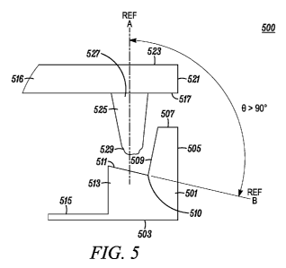
[0021] FIG. 5 illustrates a side view of a sympathetic main seal system 500
for use in
an electronic device in an unassembled state in accordance with an embodiment
of the
present invention. The sympathetic main seal system 500 comprises a lower
housing
501 which forms a portion of an electronic device (not shown). The lower
housing
501 comprises an outside wall 503 which is orthogonal to a sidewall 505. The
sidewall 505 is adjacent to an outer mating surface 507 which abuts an inner
mating
surface 517 which forms a portion of the upper housing 516. The outer mating
surface 507 is adjacent to an angular wall 509 that forms an inner face
extending
angularly from the outer mating surface 507. A compression surface 511 extends
from the angular wall 509 at an angle equal to or less than 90 degrees. As
seen in FIG.
5, compression surface 511 is formed so that it forms an angle 0 which is
greater than
90 degrees between reference line A and reference line B.
[0022] Thus, an important aspect of the invention is that the compression
surface 511
is angled outwardly with respect the direction of seal compression such that
the
compression surface 511 biases a sympathetic seal 525 (described hereinafter).
When
in compression, the sympathetic seal 525 moves in an outward manner from the
interior of the internal cavity when the lower housing 501 and upper housing
516 are
mated. Hence, an angular notch 510 that is formed at the intersection of the
angular
wall 509 and the compression surface 511 operate to bias the sympathetic seal
into a
substantially fixed position. A lateral wall 513 extends from the compression
surface
511 toward the outside wall 503 such that an inner wall 515 is formed
extending from
the lateral wall 513.
[0023] Similarly, the upper housing 516 includes an inner mating surface 517
which
substantially abuts the outer mating surface 507 when in an assembled state.
The
sidewall 521 is substantially orthogonal to the inner mating surface 517 where
an
outside wall 523 also extends orthogonally from the sidewall 521 forming an
outer
face of the upper housing 516. In order to form a watertight seal between the
lower
housing 501 and upper housing 516, the upper housing 516 comprises a
sympathetic
seal 525 which is overmolded around the perimeter of the upper housing 516.
When
not in compression, the sympathetic seal 525 has a substantially truncated
conical
6
CA 02728661 2010-12-20
WO 2010/030476 PCT/US2009/054380
CE17682DE
shape in cross section that comprises a wide end 527 that is joined with the
inner
mating surface 517 and a truncated end 529. The truncated end 529 is used to
mate
within the angular notch 510.
[0024] As described herein, the seal 525 is manufactured of silicone or like
material
and is generally referred to as "sympathetic" in view of its existence and
operation
through an affinity, interdependence, or mutual association with various
biasing
components in the lower housing 501. In other words, the sympathetic seal 525
operates as a system in combination with the angular wall 509 and compression
surface 511 used in the lower housing 510 for enabling the seal to operate
more
effectively as inward submersion pressure is increased. Hence, as the high
pressure or
"fluid" side of the sympathetic seal 25 is increased this acts to
simultaneously
increase the seal loading forces against the sealing surfaces, such as
compression
surface 511. Although some lip seals can operate in a similar "sympathetic"
manner,
the present invention is advantageous since it can be accomplished with much
less
tooling and overall complexity.
[0025] FIG. 6 illustrates a cross-sectional side view of the sympathetic main
seal
system 600 as shown in FIG. 5 in an assembled state. In contrast to FIG. 5,
the lower
housing 601 and upper housing 603 are joined in an assembled state and the
original
position of the sympathetic seal 605 is shown in phantom. Although not
specifically
shown herein, it should be evident to those skilled in the art that the lower
housing
601 and upper housing 603 may be joined using any type of mechanical fasteners
or
other hardware in order to provide a substantially tight joint between
castings forming
a cavity 618.
[0026] In order to provide a watertight seal and prevent water or other fluids
from
entering the cavity 618 when subjected to submersion pressures, the
sympathetic seal
605 is positioned within the angular notch 611. This acts to deform lower edge
607
and side edge 609 of the sympathetic seal 605. The sympathetic seal 605
deforms in a
manner in order to prevent water or other fluids from extending substantially
beyond
the angular notch 611. This occurs in view of the substantially tight seal
made
between lower edge 607 and the compression surface 613 as well as between the
side
7
CA 02728661 2010-12-20
WO 2010/030476 PCT/US2009/054380
CE17682DE
edge 609 and the angular wall 615. As seen in FIG. 6, the original shape of
the
sympathetic seal 605 is illustrated in phantom. Thus this seal is
"sympathetic" since it
ultimately works to prevent water and moisture from coming into contact with
electronic components 617, which are placed in the void between the lower
housing
601 and upper housing 603 as submersion pressure is increased.
[0027] Further, the invention may also comprise a plastic outer skin 619 which
covers the lower housing 601 and upper housing 603. The plastic outer skin 619
is a
"sealed alloy endoskeleton" concept such that the lower housing 601 and upper
housing 603 are castings that are encased in a skin 619 manufactured from
durable
plastic or other synthetic materials that does not form a seal per se but
rather serves to
protect the casting structures from vibration and shock. The plastic skin 619
also
comprises ergonomic advantages to the electric equipment such as a two-way
portable
transceiver, such that it provides improved hold, grip and overall
controllability when
operating the device.
[0028] FIG. 7 illustrates a side cross-sectional view of the sympathetic main
seal
system 700, shown in FIG. 6, illustrating the affects of water pressure which
may
enter a gap located between the lower housing 703 and upper housing 705 when
joined together. If the electronic device was submerged, water enters through
a gap
707 formed between the joint between the upper and lower housings. As water
enters
the gap 707, a leverage force is applied to the sympathetic seal 701 such that
side
edge 709 works as a lever to apply a biasing force to the lower edge 711. As
water
pressure is increased, the force between the lower edge 711 and the angular
wall 713
continues to increase its biasing force in order to prevent water or other
liquids from
breaching the interior 715 of the electronic device. In order to show
deformation of
the sympathetic seal 701, its original shape is also illustrated in phantom.
[0029] FIG. 8 illustrates a perspective view of the sympathetic main seal
system 800
that is in a single plane and can be routed around screw bosses for use with a
unique
housing geometry. The sympathetic seal 801 is overmolded in single plane in a
unitary or continuous manner to the upper surface of an electronic housing.
The
8
CA 02728661 2010-12-20
WO 2010/030476 PCT/US2009/054380
CE17682DE
geometry of the seal 801 is flexible in that it may be jogged or routed in a
semi-
circular manner 805 around a screw boss 807 or other obstacle.
[0030] FIG. 9 illustrates a side cross-sectional view of the sympathetic main
seal
system 900 where upper housing comprises a groove for increasing overmold bond
surface area between housing components. The upper housing 901 is joined with
the
lower housing 903 to form an enclosure such that the upper housing 901
comprises a
groove 905 formed within the casting for increasing the overmold bond surface
area
of the sympathetic seal 907. Both the upper housing 901 and lower housing 903
are
referred to herein as "housing", and these components may be formed of a
metallic
alloy or the like to form individual castings. The groove 905 may be either
rectangu-
lar or semi-circular in cross section for allowing the sympathetic seal 907 to
expand
into the groove cavity when in a compressed state. Since this results in an
increase in
the overall bond surface area, the use of the groove 905 works to further
prevent water
or other moisture from entering the cavity created between the upper housing
901 and
lower housing 903.
[0031] Although specific embodiments of the present invention have been
described,
those of ordinary skill in the art will appreciate that various modifications
and
changes can be made without departing from the scope of the present invention
as set
forth in the claims below. Accordingly, the specification and figures are to
be
regarded in an illustrative rather than a restrictive sense, and all such
modifications
are intended to be included within the scope of present invention. The
benefits,
advantages, solutions to problems, and any element(s) that may cause any
benefit,
advantage, or solution to occur or become more pronounced are not to be
construed as
a critical, required, or essential features or elements of any or all the
claims. The
invention is defined solely by the appended claims including any amendments
made
during the pendency of this application and all equivalents of those claims as
issued.
9