Note: Descriptions are shown in the official language in which they were submitted.
CA 02728809 2011-01-18
64371-667D
- 1 -
IMPLANTABLE PROSTHESIS
This is a divisional application of Canadian Patent Application No. 2,494,111
having an
effective filing date of May 1, 2003, and claims priority from therein.
FIELD OF THE INVENTION
The present invention relates to an implantable prosthesis and, more
particularly, to a
prosthesis for repairing or augmenting openings and/or weaknesses in a soft
tissue or muscle
wall.
DISCUSSION OF RELATED ART
Various prosthetic repair materials are known for repairing and reinforcing
anatomical
defects, such as soft tissue and muscle wall hernias. For example, in
connection with a repair
of an umbilical hernia, it is common for a surgeon to place a sheet of
prosthetic repair fabric
beneath the opening to the defect ("underlay"), above the opening to the
defect ("overlay"),
or to form the fabric into a three-dimensional shape, such as in the form of a
cone or cylinder
to "plug" the rupture. It has been recognized that puncture tracts created in
laparoscopic
surgery as a passageway for delivering instruments and prostheses to a
surgical site may be
susceptible to later herniation. Closure of the laparoscopic puncture is
typically done with a
series of sutures through the skin and/or underlying tissue and muscle, with
or without the aid
of a fabric-type or other type of prosthesis. Use of repair sutures at the
puncture wound
opening may potentially lead to complications of nerve entrapments vessel
injury, or
subsequent hernia at the defect site.
It has been suggested for certain procedures to repair an anatomical defect
using a
prosthetic fabric without reapproximating the edges of the anatomical defect.
For example,
U.S. Patent No. 5,397,331 to Himpens et at. proposes to repair a weakness of
the abdominal
wall produced by a trocar sheath using a prosthesis that includes a layer of
prosthetic material
for covering the weakness and a resilient stiffener for spreading the layer of
material into a
planar configuration. A thread extends from the repair device for routing
through the trocar
sheath so that a slight pull of the thread draws the repair device against the
peritoneum. Upon
removal of the trocar sheath, the thread may subsequently be fastened on the
skin surface to
hold the prosthesis in position.
U.S. Patent No. 5,836,961 to Kieturakis et at. proposes to repair a hernia
defect with a
patch that includes a disk and a tail that is secured to and extends from the
disk. The patch is
inserted into a patient using conventional laparoscopic instruments, and the
tail is attached to
a distal portion of an inguinal hernia sac. The hernia sac is then separated
and the pressure of
CA 02728809 2011-01-18
64371-667D
- 2 -
the insufflation gas causes the tail of the patch to be pulled upwardly into
the inguinal ring to
draw the disk against the inguinal ring.
It is an object of the present invention to provide an improved method and
prosthesis
for repairing and reinforcing soft tissue or muscle walls.
SUMMARY OF THE INVENTION
The present invention relates to an implantable prosthesis for repairing an
anatomical
defect, such as a tissue or muscle wall hernia, including an umbilical hernia,
and for
preventing the occurrence of a hernia at a small opening or weakness in a
tissue or muscle
wall, such as at a puncture tract opening remaining after completion of a
laparoscopic
procedure.
In one embodiment, an implantable prosthesis includes a body portion of
implantable,
biologically compatible material that is constructed and arranged to cover at
least a portion of
the tissue or muscle wall defect, and at least one tether extending from the
body portion and
having a cross-section with a width and thickness, the width being greater
than the thickness.
The at least one tether has a length that is sufficient to extend through the
tissue or muscle
wall defect and to be accessible from outside the patient when the body
portion is positioned
over the defect. The length of the at least one tether is at least 2.5 inches.
In another embodiment, an implantable prosthesis is provided for repairing an
existing
or potential tissue or muscle wall defect. The implantable prosthesis
comprises a body
portion of an implantable, biologically compatible material that is
constructed and arranged
to cover at least a portion of the tissue or muscle wall defect, and first and
second straps
extending from the body portion. The first and second straps are constructed
and arranged to
extend through the tissue or muscle wall defect when the body portion is
positioned over the
defect. Each of the first and second straps has a cross-section with a width
and thickness, the
width being greater than the thickness.
In yet another embodiment, an implantable prosthesis is provided for repairing
an
existing or potential tissue or muscle wall defect. The implantable prosthesis
includes a patch
of repair fabric that is constructed and arranged to cover at least a portion
of the tissue or
muscle wall defect, a resilient support member disposed on the patch to urge
the patch to a
planar configuration, and at least one tether of repair fabric that is
susceptible to tissue and
muscle integration. The at least one tether extends from the patch and
is=constructed and
CA 02728809 2011-01-18
' 64371-667D
- 3 -
arranged to extend through the tissue or muscle wall defect when the patch is
positioned over
the defect.
In a further embodiment, an implantable prosthesis is provided for repairing
an
existing or potential tissue or muscle wall defect. The implantable prosthesis
comprises a
patch of repair fabric that is constructed and arranged to cover at least a
portion of the tissue
or muscle wall defect, a resilient support member disposed on the patch, and
at least one strap
extending from the patch. The resilient support member is constructed and
arranged to urge
the patch into a planar configuration. The at least one strap is constructed
and arranged to
extend through the tissue or muscle wall defect when the patch is positioned
over the defect.
The at least one strap has a cross-section with a width and thickness, the
width being greater
than the thickness.
In another embodiment, an implantable prosthesis is provided for repairing an
existing
or potential tissue or muscle wall defect. The implantable prosthesis
comprises a body
portion of implantable, biologically compatible material that is constructed
and arranged to
cover at least a portion of the tissue or muscle wall defect, and at least one
tether extending
from the body portion and being constructed and arranged to extend through the
tissue or
muscle wall defect when the body portion is positioned over the defect. The
prosthesis also
comprises an indicator disposed on the at least one tether at a predetermined
location to
indicate a position of the body portion relative to a reference location.
In yet another embodiment, an implantable prosthesis is provided for repairing
an
existing or potential tissue or muscle wall defect. The implantable prosthesis
comprises a
patch of repair fabric that is constructed and arranged to cover at least a
portion of the tissue
or muscle wall defect, and at least one tether extending from the patch and
being constructed
and arranged to extend through the tissue or muscle wall defect when the patch
is positioned
over the defect. The patch includes first and second layers of repair fabric
that are joined to
each other to create a pocket therebetween. The patch has an access opening
that is adapted
to provide entry into an interior of the pocket to facilitate positioning of
the patch over the
tissue or muscle wall defect
In a further embodiment, an implantable prosthesis is provided for repairing
an
existing or potential tissue or muscle wall defect. The implantable prosthesis
comprises at
least one layer of repair fabric that is susceptible to the formation of
adhesions with tissue and
organs, and a resilient support member disposed on the at least one layer of
repair fabric. The
CA 02728809 2014-09-17
64371-667D
- 4 -
at least one layer of repair fabric is constructed and arranged to cover at
least a portion of the
tissue or muscle wall defect. The at least one layer of repair fabric has a
first surface for
facing the tissue or muscle wall defect and a second surface for facing away
from the tissue or
muscle wall defect. The resilient support member is constructed and arranged
to urge the at
least one layer of repair fabric into a planar configuration. The prosthesis
also comprises first
and second straps extending from the first surface of the at least one layer
of repair fabric.
The first and second straps have a length that is sufficient to extend through
the tissue or
muscle wall defect and outside the patient when the at least one layer of
repair fabric is
positioned over the defect. Each of the first and second straps has a cross-
section with a width
and thickness, the width being greater than the thickness.
In still another embodiment, a method is provided to repair an existing or
potential tissue or muscle wall defect in a patient. The method comprises
providing an
implantable prosthesis that includes a patch of repair fabric that is
constructed and arranged to
cover at least a portion of the tissue or muscle wall defect, and at least one
strap of repair
fabric extending from the patch and being constructed and arranged to extend
through the
tissue or muscle wall defect and protrude outside the patient when the patch
is positioned over
the defect. The at least one strap has a cross-section with a width and
thickness, the width
being greater than the thickness. The method also comprises introducing the
patch into the
patient; routing the at least one strap to extend through the defect and to a
region that is
accessible from outside the patient; and positioning the patch over the
defect.
In a further embodiment, there is provided an implantable prosthesis for
repairing an abdominal wall defect, the implantable prosthesis comprising: a
soft tissue repair
= patch including a first surface that is to face the defect and a second
surface that is to face
away from the defect, the first surface being configured to allow tissue
ingrowth from the first
surface and into the repair patch, the second surface being configured to
resist tissue
adhesions; and a pair of tethers, each tether including a strap portion
extending away from the
patch, each strap portion having a cross-section with a width and thickness,
the width being
greater than the thickness, each tether extending a sufficient length from the
patch to extend
through the abdominal wall defect when the patch is on one side of the defect,
so that a
CA 02728809 2014-09-17
64371-667D
- 4a -
portion of the tether is on the other side of the defect and adapted to be
pulled by a user to
position the soft tissue repair patch and/or to be secured to tissue to anchor
the soft tissue
repair patch.
Various embodiments of the present invention provide certain advantages and
overcome certain drawbacks of prior prostheses. Embodiments of the invention
may not
share the same advantages, and those that do may not share them under all
circumstances.
This being said, the present invention provides numerous advantages including
the added
advantages of ease of implantation, promotion of desired tissue or muscle
ingrowth without
involving surrounding tissue or organs, and reduction of tension at the defect
side.
1 0 Further features and advantages of the present invention, as well
as the
structure of various embodiments, are described in detail below with reference
to the
accompanying drawings.
BRIEF DESCRIPTION OF THE DRAWINGS
CA 02728809 2011-01-18
64371-667D
- 5 -
Various embodiments of the invention will now be described, by way of example,
with reference to the accompanying drawings, in which:
FIG. 1 is a top perspective view of an implantable prosthesis in accordance
with one
illustrative embodiment of the present invention;
FIG. 2 is a top plan view of an implantable prosthesis in accordance with
another
illustrative embodiment of the present invention;
FIG. 3 is a bottom plan view of the prosthesis of FIG. 2;
FIG. 4 is a cross-sectional view of a portion of the prosthesis taken along
section line
4-4 of FIG. 2;
FIG. 5 is an exploded top perspective view of the prosthesis of FIG. 2;
FIG. 6 is a top plan view of a layer of repair fabric for fabricating the
tethers of the
prosthesis of FIG. 2;
FIG. 7 is a top perspective view of the prosthesis of FIG. 2, with the access
opening
exposed to the pocket;
FIG. 8 is a cross-sectional view, similar to that of FIG. 4, in accordance
with a further
illustrative embodiment of the present invention;
FIG. 9 is a top perspective view of the implantable prosthesis of FIG. 2 used
in
conjunction with an onlay prosthesis in accordance with another illustrative
embodiment of
the present invention;
FIGS. 10-13 are schematic views illustrating repair of a trocar tract using
the
prosthesis of FIG. 2 in accordance with another illustrative embodiment of the
invention; and
FIG. 14-16 are schematic views illustrating an umbilical hernia repair using
the
prosthesis of FIG. 2 in accordance with a further illustrative embodiment of
the invention.
DESCRIPTION OF ILLUSTRATIVE EMBODIMENTS
The invention is directed to an implantable prosthesis for repairing or
augmenting
anatomical defects, and is particularly suitable for the repair of openings
in, and weaknesses
of, soft tissue and muscle walls or other anatomical regions. For ease of
understanding, and
without limiting the scope of the invention, the prosthesis to which this
patent is addressed is
described below particularly in connection with the prophylactic repair of a
trocar wound
created during laparoscopic surgery and with the repair of an umbilical
hernia. It should be
understood, however, that the prosthesis is not so limited and may be employed
in other
CA 02728809 2011-01-18
64371-667D
- 6 -
anatomical procedures, as would be apparent to one of skill in the art. For
example, the
prosthesis may be used for the repair or augmentation of a tissue or muscle
wall hernia, such
as an incisional hernia, an inguinal hernia, a ventral hernia, a femoral
hernia, and other tissue
or muscle wall openings, as well as other puncture wounds or defects in
addition to those
formed by, and then left on removal of, a trocar and/or cannula.
The invention is more particularly directed to a repair device that includes a
patch or
plug having a body portion that is larger than at least a portion of the
opening or weakness so
that placement of the body portion against the defect will cover or extend
across that portion
of the opening or weakness. The repair device further includes at least one
tether that extends
from the patch or plug and may be manipulated by a surgeon to position the
patch or plug
relative to the repair site and/or to secure the patch or plug relative to the
opening or
weakness in the tissue or muscle wall. The tether may be configured to extend
through the
defect and outside a patient's body to allow a surgeon to position and/or
manipulate the patch
from a location outside the body. A portion of the tether may be attached
directly to anatomy
surrounding the edges of the defect opening or to other neighboring tissue,
muscle, skin or
other anatomy, using a suture, staple, tack or other attachment device whether
separate from
or integrally formed with the tether, so as to anchor the patch in place. Any
excess tether
may then be removed.
An indicator may be arranged on the tether to aid a surgeon in determining
when the
patch or plug has been inserted a sufficient depth or distance within a
patient. The indicator
may be located a desired distance from the patch or plug such that its
location relative to a
reference location provides an indication as to the position of the patch or
plug within the
patient without direct visualization of the patch or plug.
The tether may be configured as a strap having a cross-section with a width
that is
greater than its thickness. The strap configuration presents a relatively
large surface area for
the tether that may enhance the amount of tissue integration to the tether, if
desired. The
strap configuration may also, or alternatively, act to distribute applied
forces acting on the
tether across a relatively large area of the patch or plug as compared to a
small area of the
patch or plug as could occur if the tether was in the form of a length of
suture material. The
width of the tether may extend across a portion or approximate the width of
the body portion
of the patch or plug. However, it should be appreciated that the invention is
not limited in
CA 02728809 2011-01-18
* 64371-667D
- 7 -
this respect, and the tether may have any suitable width, and its width may
vary along the
length of the tether.
The tether may be joined to the patch or plug at one or more junctions so that
forces
acting through the tether may be applied to the patch or plug at those
junctions. Multiple
tethers may be joined to the patch or plug to enhance the positioning and
anchoring of the
patch or plug.
The tether may be configured from an elongated strip of a biologically
compatible,
implantable material, such as a knit fabric, or may be solid or substantially
non-porous. The
tether may be formed of a fabric that either enhances tissue integration,
inhibits adhesions
with tissue, or is a combination of both, as desired. The material of the
tether may be
permanent or absorbable. The patch or plug, similarly, may be formed of a
tissue infiltratable
material such as a knit fabric, or may be composed of a solid or substantially
non-porous
material. The tether and/or the patch or plug may be formed of one or more
layers of the
same or dissimilar material. The tether and the patch or plug may be formed
with portions
that are tissue infiltratable and other portions that are non-tissue
infiltratable, providing
selected areas of the repair device with different tissue ingrowth and
adhesion resistant
properties.
The repair device may be placed at the defect site using an open surgical
procedure,
by laparoscopically passing the patch or plug through a cannula that extends
along a puncture
tract leading to the defect, such as may be formed naturally or by a trocar,
or through a hybrid
procedure where an incision is formed through the skin and then a tract is
created in the
underlying tissue and/or muscle leading to the defect site along which the
repair device is
transported. The patch or plug may be flexible, allowing reduction of the
repair device, such
as by folding, rolling or otherwise collapsing the patch or plug, into a
slender configuration
suitable for delivery along the puncture tract, or a cannula extending through
the puncture
tract, to the defect site. Upon exiting the puncture tract or cannula, the
patch or plug may
automatically unfurl or may be unfolded, unrolled or otherwise deployed by the
surgeon to an
unfurled or expanded configuration suitable to repair the weakness or opening.
A support member may be arranged in or on the patch or plug to help deploy the
patch or plug at the surgical site and/or help inhibit collapse or buckling of
the patch or plug.
The support member may be configured as a complete or partial loop or a ring,
criss-cross, x-
shape, or any other suitable arrangement that helps to maintain a desired
shape, and/or
CA 02728809 2011-01-18
64371-667D
- 8 -
position, of the patch or plug despite tension forces that may be applied on
the repair device
through the tether. The support member may be rollable, foldable or otherwise
collapsible,
when the patch or plug is reduced in size for puncture tract or cannula
delivery, and may
spring back, either automatically or upon the influence of a force (e.g., body
heat where the
support is formed of a shape memory material, such as NITINOL) to its expanded
shape on
deployment at the repair site, influencing the patch or plug to assume its
unfurled or
expanded configuration.
The patch or plug may be configured with a pocket or cavity to facilitate the
deployment and/or positioning of the patch or plug over the opening or
weakness. An access
opening may be provided to allow access to the interior of the pocket. In this
manner, the
surgeon may place one or more fingers or an instrument through the access
opening and into
the pocket to ensure proper deployment and placement of the patch or plug.
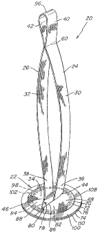
FIG. 1 illustrates one embodiment of a prosthesis 21 for repairing or
augmenting soft
tissue and muscle wall defects, such as an umbilical hernia or a trocar wound
created in the
abdominal wall of a patient during a laparoscopic surgery.
The prosthesis 21 includes a body portion 22 of implantable, biologically
compatible
material that is configured to cover at least a portion of the defect. As
shown, the body
portion includes a patch that may be used as an underlay or an overlay. The
patch may be
configured with any desired strength, flexibility, tissue integration,
adhesion resistance and/or
other characteristics suitable for the repair as would be apparent to one of
skill. Although the
body portion of the prosthesis is described in connection with a patch-type
embodiment, the
body portion may include a plug, a combination plug and patch, and other
suitable
arrangements for mending the defect.
The prosthesis also includes a tether 24 extending from the patch 22 to
facilitate
positioning and/or anchoring of the patch within a patient's body. As shown,
the tether
extends from a surface 34 of the patch that is to face the defect 28 when the
patch 22 is
implanted in the patient's body. In this manner, the tether may be routed
through the defect
and manipulated to position the patch over the defect. It should be
appreciated that the tether
may extend from any suitable portion of the patch. Additionally, two or more
tethers may be
provided on the patch.
Since many tissue and muscle wall defects are relatively small and/or space
may be
limited at the defect site, access to the patch either directly or using tools
may be difficult for
CA 02728809 2011-01-18
64371-667D
- 9 -
manipulating and/or positioning it over the defect. Consequently, the tether
24 may be
configured to extend through the anatomical defect to a location that is
readily accessible to
the surgeon either within or outside the patient's body. In this manner, the
surgeon may
grasp and manipulate the proximal end 40 of the tether to position the patch
within the body
and against the defect. For example, after the patch is deployed at the defect
site, the surgeon
may pull on the tether to draw the patch into position over the defect.
In certain procedures, including laparoscopic and open repair procedures, the
surgeon
may desire to manipulate the patch 22 from outside the patient's body. In this
regard, the
elongated tether 22 may be configured with a length that is sufficient to
extend from the
implanted patch, through the defect and to a region that is accessible from
outside of the body
of the patient. Preferably, the tether is sized so that it protrudes outside
the patient's body
when the prosthesis is implanted at the defect site to provide ready access to
the tether by the
surgeon.
The length of the tether may be dictated by the location of the defect and/.or
the repair
procedure. For example, a short tether may be sufficient for repairing an
umbilical hernia
using open surgery, while a longer tether may be desired for a laparoscopic
procedure in
which the tether extends through a cannula. In one illustrative embodiment,
the tether 24
may be configured with a length that ranges from approximately 2.5 inches to
approximately
20 inches. In one embodiment for repairing an umbilical hernia, the length of
the tether is at
least 2.5 inches, preferably at least 4 inches, more preferably at least 7
inches, and even more
preferably approximately 9 inches. In another embodiment for repairing a
defect using a
laparoscopic procedure, the length of the tether is at least 10 inches,
preferably at least 12
inches, more preferably at least 14 inches, and even more preferably
approximately 15 inches
for use with a cannula having a length of 6-6.5 inches. It is to be
appreciated that the
disclosed tether lengths are exemplary and that any suitable tether length may
be employed
for a particular repair.
In some procedures, it may be difficult for a surgeOn to determine when the
patch 22
has been inserted a required distance into the body to be positioned at the
repair site. In one
illustrative embodiment, the tether 24 may include an indicator 60 disposed a
predetermined
distance from the patch. The appearance or disappearance of the indicator 60
proximate the
edge of the wound or the proximal end of a cannula acknowledges that the patch
22 has been
inserted a desired depth within the body cavity of the patient without direct
visualization of
CA 02728809 2011-01-18
64371-667D
- 10 -
the patch, such as with a camera. For example, when the indicator 60 is
located proximate
the proximal end of the cannula during laparoscopic insertion of the patch,
the indicator may
reveal that the patch has passed through the cannula and is deployed at the
defect site. As a
representative example, for a cannula having a length of approximately 6-6.5
inches, the
indicator may be located approximately 7.5-8.5 inches from the patch. However,
it should be
appreciated that the invention is not limited in this respect and that the
prosthesis 20 need not
employ an indicator 60.
In one illustrative embodiment, the indicator 60 includes a series of stitches
formed
with a thread having a contrasting color as compared to the material of the
tether. For
example, the thread of the indicator may be colored blue and the tether may be
colored white.
It is to be appreciated that other suitable indicators formed in other
suitable manners may be
employed. For example, contrasting ink or dyes may be applied to the tether,
or the material
of the tether may be treated to change its appearance, texture, or shape, such
as with a heat
seal or indentation, to indicate the implantation depth of the patch. One or
more indicators 60
may be disposed on the tether at multiple locations to indicate various
desired or optional
implantation locations of the patch. For example, two or more indicators may
be located on
the tether for use with cannulas of differing lengths. The indicator 60 may
also numerically
indicate the depth of the implanted patch with a measured and/or numbered
indicator or ruler
disposed on the tether. The indicator may be preformed on the tether, or
alternatively, may
be formed on the tether by the surgeon at the desired implantation depth of
the patch for a
particular procedure.
As illustrated, the tether 24 has a strap-like configuration having a cross
section with a
width that is greater than its thickness. The strap configuration may
distribute forces over a
larger region of the patch as compared to a suture-like tether. The strap may
also present a
relatively large surface area that may facilitate the repair, such as by
enhancing tissue
integration to the tether, if desired. Although the tether 24 is shown as
having a constant
width along its length, the invention is not limited in this respect, and
other strap
configurations may be suitable. For example, the width of the strap may vary
along the
length such that the strap is wider at its distal end and narrower at its
proximal end. It is to be
appreciated, however, that the tether is not limited to a strap configuration
as the prosthesis
may employ any suitable tether configuration apparent to one of skill.
CA 02728809 2011-01-18
64371-667D
- 11 -
The tether may be joined to the patch 22 using any suitable fastener or
attachment
arrangement. In the illustrative embodiment, the tether 24 includes a base or
foot that is
stitched to the patch 22 along a stitch line 23. It is to be appreciated that
other suitable
attachment methods may be employed including, but not limited to, bonding,
adhesives and
other attachment methods apparent to one of skill in the art. Alternatively,
the tether may be
integrally formed with the patch, such as by forming the tether and a portion
of the patch
from the same piece of material.
The strap configuration may also reduce potential tearing of the tissue and
muscle at
the edge of the defect 28 by the tether 24 during and after the repair
procedure, particularly
when compared to a suture-like tether. In this regard, the large surface area
of the tether may
resist tearing of the tissue and muscle proximate the defect when the tether
is pulled during
the procedure. In addition, the large width of the tether may resist tearing
through the tissue
and muscle proximate the defect during the healing process.
The tether is preferably flexible along its length from its distal end 36 to
its proximal
end 40 to facilitate repair of a defect. To facilitate repair of a defect, the
tether may be
formed of a repair fabric that permits or is otherwise susceptible to tissue
or muscle
integration. In one embodiment, the tether may include a plurality of
interstices or openings
which allow sufficient tissue or muscle wall ingrowth to secure each tether to
host tissue or
muscle after implantation. However, the invention is not limited in this
respect and the tether
may be formed of a material or otherwise configured to enhance tissue
integration, inhibit
adhesion, or a combination of both, as desired.
The patch may be anchored over to repair the tissue or muscle wall defect by
attaching the tether 24 to or proximate the edge of the tissue or muscle
defect. The tether
may be attached to tissue, skin, and/or muscle using any suitable attachment
methods
apparent to one of skill in the art, such as sutures, tacks, and/or staples.
In this manner, the
defect may be repaired in a tension free manner since it is not necessary to
reapproximate the
tissue at the defect and/or to attach the patch directly to tissue or muscle
in the region of the
defect.
The patch 22 may be configured to have any suitable shape or size that is
conducive
to facilitating the correction or repair of a particular defect. In the
embodiment shown in
FIG. 1, the patch 22 has a relatively flat configuration. However, the patch
need not be flat,
and 'convex, concave, convex/concave, and more complex three-dimensional
shapes also are
CA 02728809 2011-01-18
' 64371-667D
- 12 -
contemplated, as noted above. The patch may be pliable to facilitate
manipulation and/or
reduction of the patch during delivery to the defect and/or to conform the
patch to the
anatomical site of interest. As illustrated, the patch has a generally
circular shape. Examples
of other shapes include, but are not limited to, oval, square, rectangular,
and irregular
configurations. The patch 22 may be sized to cover part or, preferably, all of
the defect. In
one embodiment, the patch 22 is sized to extend slightly beyond the edge
margins of the
tissue or muscle wall defect. It should be understood, however, that any
suitable size and
shape may be employed for the patch.
The patch 22 may include one or more layers of repair fabric that may promote
tissue
ingrowth to the patch, inhibit adhesions to the patch, or a combination of
both. In one
illustrative embodiment, the patch includes an ingrowth layer 64 having a
plurality of
interstices or openings which allow sufficient tissue or muscle ingrowth to
integrate the
prosthesis with the host tissue or muscle after implantation. Preferably, the
ingrowth layer is
formed of the same tissue infiltratable material used for the tether. However,
the invention is
not limited in this respect, as the ingrowth layer may be formed of any
suitable biologically
compatible material apparent to one of skill.
To inhibit collapse of the patch 22 into the defect 28 when force is applied
to the
tether, and/or to help deploy the patch into a planar configuration, it may be
desirable to
employ a patch that is sufficiently rigid so that it can be easily and
effectively manipulated
and positioned in the desired area, yet sufficiently flexible so that the
patch is adequately
tolerated by both the physician implanting the patch and the patient receiving
the patch. In
one illustrative embodiment as shown in FIG. 1, to balance the stiffness and
flexibility
characteristics, the prosthesis 21 includes a resilient support member 98 to
reinforce portions
of the patch 22 and to urge the patch to a planar configuration. The support
member 98 may
be coupled to the patch 22 in any suitable manner, as the present invention is
not limited in
this respect. Suitable attachment methods include, but are not limited to,
stitching, bonding,
adhesive, and integral formation with the repair fabric of the patch, as will
be discussed
further below.
=
The resilient support member 98 contributes to the stability of the patch 22,
allowing
it to deploy into and remain in a desired shape. For example, the support
member may aid in
returning the patch to a substantially unfurled or expanded configuration
after the folded up
or otherwise reduced implant has been delivered through the cannula. This
stability
CA 02728809 2011-01-18
64371-667D
- 13 -
facilitates deployment and placement of the patch by making it easy to handle.
Also, this
stability minimizes the tendency of the patch to sag, fold, bend, collapse, or
otherwise be
dislocated. Difficulty in handling, dislocation or bending could require
additional operative
procedures and/or additional anchoring during implantation.
As indicated above, a prosthesis for repairing or augmenting soft tissue and
muscle
wall defects, such as an umbilical hernia or a trocar wound created in the
abdominal wall of a
patient during a laparoscopic surgery, may include a body portion of any
suitable
configuration and one or more tethers extending from the body portion. =
In another illustrative embodiment shown in FIGS. 2-7, the prosthesis 20
includes a
patch 22 for covering at least a portion of the defect, and a pair of tethers
24, 26 extending
from the patch to facilitate positioning and/or anchoring of the patch at the
defect site. As
shown, the tethers extend from a surface 34 of the patch that is to face the
defect 28 when the
patch 22 is implanted in the patient's body so that the tethers may be routed
through the
defect. Each tether is configured with a length that is sufficient to extend
through the defect
to a region that is accessible from outside the body, as described above.
Additionally, each
tether has a strap-like configuration similar to the embodiment of FIG. I. It
is to be
understood, however, that the tethers may be configured with any suitable size
and shape
apparent to one of skill.
As illustrated in the embodiment of FIGS. 2-7, the tethers 24, 26 extend from
the
patch at spaced apart junctions 44, 46 between the tethers and the patch 22.
In this manner,
the spaced junctions transfer forces from the tethers to different portions of
the patch, rather
than applying the forces in a more concentrated region. This arrangement may
enhance force
distribution across the patch so as to reduce the potential for collapsing the
patch into the
defect and pulling the patch through the defect. The spaced junctions between
the tethers and
the patch may also facilitate positioning and manipulation of the patch. In
this regard,
tension may be applied to one or the other of the tethers to guide or direct
the patch, similar to
reins. However, it should be appreciated that the invention is not limited in
this respect, and
that the tethers may be joined or attached to the patch in other suitable
locations.
To secure the patch 22 to repair the tissue or muscle wall defect without
reapproximating the tissue or muscle surrounding the defect, the tethers 24,
26 may be
attached to opposite edges of the tissue or muscle defect. In this manner,
forces applied to
the patch 22 by the tethers are relatively balanced to the body of the patch,
and thus, facilitate
CA 02728809 2011-01-18
= 64371-667D
- 14 -
maintenance of the patch in its desired implantation position. It is to be
appreciated that other
suitable attachment arrangements of the tethers may be used as would be
apparent to one of
skill. For example, the tethers may each be attached to the same side of the
defect. As
described above, the tethers may be attached to the tissue, skin, and/or
muscle using suitable
attachments known in the art, such as sutures 54, tacks, and/or staples. In
this manner, the
defect may be repaired in a tension free manner since it is not necessary to
reapproximate the
tissue at the defect, and the patch is anchored over the defect with the
tethers secured to the
opposing edges of the defect.
In certain repairs, it may be desirable to vary forces at different regions of
the patch.
In one embodiment, the tethers 24, 26 may be joined to the patch 22 at
junctures 44, 46 which
are not symmetric about the center of the patch. In another embodiment, one
strap 24 may be
longer than the other strap 26 after the straps are attached to secure the
patch 22. In this
manner, extending the tethers from different locations of the prosthesis
and/or employing
straps of differing lengths or sizes may act to spread the forces to the patch
in a
predetermined manner.
As illustrated, the prosthesis may include an indicator 60, as described
above, as an
aid for a surgeon in determining when the patch 22 has been inserted a
sufficient distance
within the patient. The indicator 60 may be provided on either one or both
tethers 24, 26. In
the illustrative embodiment of FIGS. 2-7, the indicator includes a thread that
attaches the
tethers to each other.
In certain procedures, such as a laparoscopic procedure, the prosthesis 20 may
be used
to repair a fairly small trocar wound that itself may be too narrow for
delivery of the patch
22. One approach is to deliver the patch 22 and the attached tethers 24, 26 to
the wound site
28 through a separate cannula or entry wound that is large enough to
accommodate transport
of the patch. In this manner, the patch may be deployed at or near the slender
trocar wound
and at least a portion of the tethers are accessible for the surgeon to
retrieve and extract the
tethers through the defect 28. The tethers may then be pulled, pushed, or
otherwise
manipulated. In this manner, the indicator of a contrasting color may help the
surgeon locate
the tethers inside the body cavity to ease the extraction of the tethers
through the defect to be
repaired.
CA 02728809 2011-01-18
64371-667D
- 15 -
In the illustrative embodiment of FIGS. 2-7, the prosthesis 20 includes a
patch 22
which is relatively flat and circular. However, the patch need not be flat
and/or circular, and
three dimensional and other shapes may be suitable, as discussed above.
The patch may include an ingrowth layer 64 of tissue infiltratable material to
enhance
the repair of the defect. The ingrowth layer includes at least one layer of
repair fabric that
permits or is otherwise susceptible to tissue or muscle ingrowth. In the
embodiment of FIGS.
227, the ingrowth layer 64 includes first and second layers 66, 68. Each layer
66, 68 is
formed of a biologically compatible, flexible repair material that includes a
plurality of
interstices or openings which allow sufficient tissue or muscle ingrowth to
integrate the
prosthesis with host tissue or muscle after implantation. Multiple layers of
tissue infiltratable
fabric may enhance the strength of the patch and/or the amount of tissue
ingrowth to the
patch. Preferably, the first and second layers are formed of the same tissue
infiltratable
material as that of the tethers. However, the invention is not limited in this
respect, and either
one or both layers may be formed of any biologically compatible material,
suitable for
repairing a tissue or muscle wall defect as would be apparent to one of skill.
In one embodiment, the tethers 24, 26 and ingrowth layers 64, 66, 68 of the
prostheses
20, 21 are formed from a sheet of knitted polypropylene monofilament mesh
fabric such as
TM
. BARD MESH available from C.R. Bard, Inc. When implanted, the polypropylene
mesh
promotes rapid tissue or muscle ingrowth into and around the mesh structure.
Alternatively,
other surgical materials which are suitable for tissue or muscle reinforcement
and defect
TM
correction may be utilized including SOFT TISSUE PATCH (rnicroporous ePTFE -
TM
available from W.L. Gore & Associates, Inc.); SI IRGTPRO (avatiable from US
Surgical,
TM TM TM
Inc.); TRELEX (available from Meadox Medical); PROLENE and MERSILENE
(available
from Ethicon, Inc.); and other mesh materials (e.g., available from Atrium
Medical
TM
Corporation). Absorbable materials, including oolyglactin (VICRYL ¨ available
from
TM
Ethicon, Inc.) and polyglycolic acid (DEXON -- available from US Surgical,
Inc.), may be
suitable for applications involving tempprary correction of tissue or'muscle
defects. Collagen
TM
materials such as COOK SURGISIS, available from Cook Biomedical, Inc. may also
be used.
It also is contemplated that the mesh fabric may be formed from multifilament
yarns and that
any suitable method, such as knitting, weaving, braiding, molding and the
like, may be
employed to form the tether mesh material. Alternatively, the tether may be
formed of a
monofilament of any of the above materials or a suture material, which may be
absorbable or
CA 02728809 2011-01-18
64371-667D
- 16 -
non-absorbable. It is preferable that the material of the tether have a
tensile strength of
approximately 3 lb. force or more.
To ensure adequate tissue ingrowth to the patch occurs, the layers 66, 68 may
be
attached or joined in a way that would permit tissue to grow into the pores of
the first and
second layers and provide a strong bond between the surrounding muscle or
tissue in the first
and second layers. In one embodiment, the first and second layers are
connected with
stitches 70, 72 proximate the periphery 74, 76 of each layer.
It should be appreciated that the invention is not limited to any particular
attachment
method, as the first and second layers 66, 68 may be attached using other
suitable techniques.
For example, the layers may be bonded together by melting the layers at
specific locations or
in a specific pattern; sonic, induction, vibration, or infrared/laser welding
the layers; or using
a suitable bonding agent. The point or points of attachment may comprise any
suitable
pattern, such as a spiral pattern, a serpentine pattern, or a grid-like
pattern of dots or beads,
that maintains a sufficient quantity of open or non-impregnated interstices
for tissue or
muscle infiltration.
To aid in deploying and/or positioning the patch during implantation, the
patch 22
may include a pocket 78. En this manner, a physician may use the pocket 78 to
deploy or
position the patch in the desired area or implantation location. In the
embodiment shown in
FIGS. 2-7, the first and second layers 66, 68 are attached in a manner to form
a pocket 78
therehetween. However, it should be appreciated that the invention is not
limited in this
respect and that a pocket need not be employed or that other suitable pockets
formed in other
suitable manners may be employed. For example, a pocket may be formed from an
additional layer of material or portion thereof attached to the first layer 66
and/or the second
layer 68.
To gain access to the interior of the pocket 78, the patch 22 includes an
access
opening 80. In one embodiment, the opening 80 includes a transverse cut or
slit formed in
the second layer 68 which may follow a diameter of the patch. It should be
recognized that
the access opening may be oriented in any position and located across any
portion of the
patch as may be suitable for the repair procedure.
To position and/or deploy the patch, the surgeon may insert one or more
fingers (or
suitable surgical instrument) through the access opening and into the pocket
to manipulate the
patch into place. In one embodiment, the pocket 78 is sized to accept at least
one finger of
CA 02728809 2011-01-18
64371-667D
- 17 -
the surgeon's hand or a tool for positioning the implant, although other
suitably sized pockets
may be employed as the present invention is not limited in this respect.
Further, the pocket
may be formed as multiple pockets so that one or more fingers or instruments
may be inserted
into individual sections. In the embodiment shown in FIGS. 2-7, the pocket 78
includes a
first side pocket 82 and a second side pocket 84 on opposing sides 86, 88 of
the opening.
However, it should be appreciated that the invention is not limited in this
respect and that
only a single central or off-set pocket may be employed.
As illustrated, the tethers 24, 26 are attached to the second layer of fabric
68, which is
itself attached to the first layer of fabric 66 at its periphery 74, 76. As
force is applied to the
tethers, the second layer of fabric will tend to billow from the first layer
of fabric. The forces
on the tethers are transmitted through the second layer of fabric and to the
first layer of fabric
at the peripheral attachment of the first and second layers of repair
material. In this manner,
the attachment of the tethers to the second layer may act to inhibit collapse
of the prosthesis
by spreading forces to the periphery of the patch.
The tethers 24, 26 may be attached to the second layer of fabric 26 on
opposing sides
86, 88 of the access opening 80, as shown in FIGS. 2-7. As force is applied to
the tethers, the
billowing second layer 68 may open and expand the access opening 80 to the
pocket 78. The
gaping access opening spreads or spaces apart the junctions 44, 46 of the
tethers 24, 26 and
the patch. In this manner, the temporary spacing of the junctions 44, 46
spreads the forces on
the tethers away from the center and towards the periphery of the patch.
To further enlarge the access opening 80 during the repair procedure, the
surgeon may
pull the tethers 24, 26 away from each other. In this manner, the access
opening can be
drawn open, allowing less restricted access to the pocket 78 to position or
manipulate the
patch. The exposed access opening between the tethers and through the defect
may also
facilitate access to the broad surface 30, 32 of the tethers 24, 26 when
attaching the tethers to
the edges of the defect. Additionally or alternatively, sutures, staples, or
tacks (not shown)
may be placed through the patch, if desired, into surrounding tissue and/or
muscle to secure
the prosthesis.
= To facilitate the fabrication of the prosthesis, the tethers may be
integrally formed
with the second fabric layer. In one illustrative embodiment shown in FIG. 6,
an elongated
piece of repair fabric includes a pair of layer portions 68A, 68B disposed at
opposite ends of
an elongated strap. The layer portions may be configured so as to form a
desired shape of the
CA 02728809 2011-01-18
64371-667D
- 18 -
second fabric layer. As shown, each layer portion 68A, 68B may be configured
with a semi-
circular shape to form a circular second layer when combined. The strap may be
folded in
half along a fold line 96 to form the first and second tethers 24, 26 between
the fold line 96
and the layer portions. Each half of the second layer of fabric may be folded
out to form the
generally planar second layer 68 at the distal end of the tethers. In this
manner, the access
opening 80 is formed between the two tethers and each half of the second layer
of fabric.
As illustrated, the proximal ends 40, 42 of the tethers are joined to form a
loop or
handle that may be grasped and pulled by the surgeon. If desired, the proximal
ends of the
tethers may be separated before, during, or after implantation of the
prosthesis. It should also
be appreciated that the tethers 24, 26 may be separately attached to the patch
in other suitable
locations. Additionally, the tethers may be joined to any one or all layers of
the patch.
To inhibit collapse of the patch 22 into the defect 28 when force is applied
to the
tethers 24, 26, and/or to help deploy the patch into a planar configuration, a
resilient support
member may be disposed on the patch. In one embodiment, the resilient support
member 98
includes a substantially continuous loop or ring positioned adjacent the outer
margin 100 of
the patch 22. In the embodiment shown in FIGS. 2-7, the support member 98 is
spaced
inwardly from the outer peripheral edges 74, 76 of the layers of fabric 66,
68. However, it
should be appreciated that the present invention is not limited in this
respect, as the support
member may be disposed at the peripheral edge and/or at discrete locations
throughout the
body of the patch.
In the embodiment shown, the support member 98 includes a monofilament of a
desired thickness and cross-sectional shape to provide a desired degree of
resilience or
rigidity. It should be appreciated that the support member may have any cross-
sectional
shape, such as circular, square, rectangular, triangular, elliptical, etc. The
support member
may be configured on the patch in any pattern, such as a spiral pattern, a
square pattern, an
elliptical pattern, a circular pattern, criss-cross pattern or the like.
The stiffness or rigidity of the support member may be varied depending on the
size
of the patch. For example, the cross-sectional diameter and/or the spring
constant of the
material of the monofilment thread may be varied in a manner to provide a
desired stiffness.
In one embodiment, for a patch 22 having a diameter of approximately 1.75
inches,
the support member 98 is formed from a segment of 0.03 inch polyethylene
terephthalate
(PET) monofilament thread having a length of approximately 3.375 inches. In
this manner,
CA 02728809 2011-01-18
' 64371-667D
- 19 -
the monofilament thread may be formed into a loop having a diameter of
approximately 1.1
= inches. In another embodiment for a patch having a diameter of
approximately 2.5 inches,
the support member may be formed from a segment of 0.030 inch PET monofilament
thread
having a length of 5.94 inches. In this manner, the monofilament thread may be
formed into
a loop having a diameter of approximately 1.81 inches. However, it should be
appreciated
that the invention is not limited in this respect and that the support member
may be made of
any suitable material including nylon, polypropylene, and polyester and having
any suitable
diameter or cross-section.
The support member 98 may be disposed on the patch 22 in any suitable manner
as
the present invention is not limited in this respect. In one embodiment, as
shown in FIGS. 2-
7, the resilient support member 98 is sandwiched between the first and second
layers of repair
fabric 66, 68 and may or may not be physically attached thereto. The support
member may
be tightly or loosely held within a channel 102 between the first and second
layers 66, 68 and
formed by a pair of seams joining the first and second layers. In the
illustrative embodiment,
the channel 102 is formed by a pair of seams 70, 72 that follow the contour of
the periphery
74, 76 of the layers. The seams may be formed by a series of stitches
extending along.the
outside and inside edge of the resilient support member 98 to keep it from
moving with
respect to the first and second layers. Because of the rigidity of the
resilient support member,
one seam extending along one side of the support member may be sufficient.
Alternatively, rather than being sandwiched between the first and second
layers 66,
68, the support member 98 may overlie or underlie the ingrowth layer 64 and
may be
attached, regardless of location, with stitches or a bonding agent, or fused
with ultrasonic,
induction, vibration, infrared/laser welding and the like. Alternatively, the
support member
may be woven through at least one of the layers or integrally formed with one
or both layers
as the layer itself is being made.
Although the support member 98 is described as being formed of a monofilament,
other suitable constructions may be employed. For example, the support member
may be
molded elements that are subsequently attached to the patch or molded onto the
patch. As
another example, the support member may be formed from the ingrowth layer 64.
In this
respect, the support member may be formed by melting a portion of the ingrowth
layer in any
desired shape. The support member may be formed by applying heat to the
ingrowth layer at
a temperature range of approximately 320 F to 400 F for a period of
approximately 3-5
CA 02728809 2011-01-18
64371-667D
- 20 -
seconds. In another example, the support member may be formed by multiple
stitches
passing through one or both layers, such as, for example, an embroidered
section.
Alternatively, the support member may be formed by altering the weave pattern
in a zone of
desired reinforcement. In this manner, the area of the ingrowth layer where
tissue ingrowth is
desired may be formed with a relatively loose open weave, whereas the area or
zone of
reinforcement may be formed with a relatively tight weave, to provide the
desired rigidity.
Other suitable methods or mechanisms to form the support members may be
employed, as the
present invention is not limited in this respect. Although some embodiments
described above
include support members, the present invention is also not limited in this
respect.
In certain procedures, such as in the repair of trocar wounds in the chest or
abdominal
wall or groin region, it may be desired to limit or prevent contact between
the ingrowth layer
64 and certain tissue, muscle or organs. Such contact could potentially lead
to undesirable
postoperative adhesions between the ingrowth layer and the surrounding tissue,
muscle or
organ and/or erosion of the ingrowth layer into the neighboring anatomy or
other injury. To
minimize or eliminate the incidence of postoperative adhesions to selected
portions of the
patch 22, or other trauma, the prosthesis 20 may include an adhesion resistant
barrier
overlying at least a portion, and preferably all, of one side of the ingrowth
layer.
In one illustrative embodiment as shown in FIGS. 2-7, a barrier layer 104 is
attached
to the side 106 of the patch 22 adjacent the first layer 66 that is to face
away from the defect
28. The patch 22 is to be positioned in the patient such that the barrier
layer 104 faces the
region of potential undesired adhesion, such as the abdominal viscera (e.g.,
intestines) or the
thoracic viscera (e.g., heart or lungs). The barrier layer is formed of a
material and/or with a
structure that does not substantially stimulate and, in certain embodiments,
may resist tissue,
muscle or organ ingrowth and adhesion formation when implanted, thereby
reducing the
incidence of undesired postoperative adhesions between the ingrowth layer 64
and adjacent
tissue, muscle or organs.
In one embodiment, the barrier layer 104 is formed from a sheet of expanded
polytetrafluoroethylene (ePTFE) having fibril lengths ¨ also referred to as
pore size or
internodal distance ¨ that will not permit significant tissue ingrowth. In one
embodiment, the
fibril lengths of the ePTFE are less than 5 microns. In another embodiment,
the fibril lengths
of the ePTFE are less than 1 micron and in still another embodiment, the
fibril lengths are
less than 0.5 microns. Examples of other suitable materials for forming the
barrier layer 104
CA 02728809 2011-01-18
=
64371-667D
21
TM
TM
include FLUORO-TEX Pericardial and Peritoneum Surgical Membrane and FLUORO-TEX
TM
Dura Substitute available from C.R. Bard and PRECLUDE Pericardial Membrane,
TM
TM
PRECLUDE Peritoneal Membrane and PRECLUDE Dura Substitute inembrane available
from W.L. Gore & Associates, inc. A representative and non-limiting sampling
of other
TM ,
suitable micro to non-porous materials includes silicone elastomer, such as
SILASTEC Rx
Medical Grade Sheeting (Platinum Cured) distributed by Dow Corning
Corporation, and
microporous polypropylene sheeting (available from Celgard, Inc.) and film.
Autogenous,
heterogenous and xenogeneic tissue also are contemplated including, for
example,
TM
pericardium and small intestine submucosa. Absorbable materials, such as
SEPRAFILM
available from Genzyrne Corporation and oxidized, regenerated cellulose
(Intercede (TC7))
may be employed for some applications. It is to be appreciated that other
suitable
biocompatible adhesion resistant materials also may be used.
To permit and facilitate tissue or muscle growth into the first layer of
repair material
66, the barrier layer 104 is preferably attached to the first layer 66 in a
way that would permit
tissue to grow into the pores of the first layer and provide a strong bond
between the
surrounding muscle or tissue and the first layer. In one embodiment, the
barrier layer is
attached to the ingrowth layer with stitches. Although the attachment is shown
to include
concentric patterns of stitch lines, any suitable pattern may be employed so
as to minimize
separation of the ingrowth layer 64 and the barrier layer 104, to minimize the
number of
stitching holes through the barrier layer and to facilitate the manufacturing
process. It should
also be appreciated that the barrier layer may be attached using other
suitable materials,
techniques and/or patterns. For example, the barrier layer may be bonded to
the ingrowth
layer by heating the layers, by welding the layers, or using a suitable
bonding agent. Any
suitable pattern, such as a spiral pattern, a serpentine pattern, or a grid-
like pattern of dots or
beads may be used provided there is a sufficient quantity of open or non-
impregnated
interstices maintained in at least one layer for tissue and muscle
infiltration.
In one embodiment, as shown in FIGS. 2-7, the first and second layers of
repair fabric
66, 68 are attached together and to the barrier layer at discrete attachment
lines using stitches,
which allow sufficient tissue infiltration to the ingrowth layer, while
providing a connection
between the first and second layers and the barrier layer. In addition, some
or all of the
stitches may be used to secure only the first and second layers of repair
fabric. In the
embodiment shown, the first or outer line of stitches 70 attach only the first
and second layers
CA 02728809 2011-01-18
64371-667 D
22
of repair fabric 66, 68, whereas the second or inner line of stitches 72,
forming the channel
102 for the resilient support member 98, attach the first and second layers of
repair fabric 66,
68 with the barrier layer 104. In this manner, the number of holes created by
stitches in the
barrier layer 104 are decreased to minimize the leakage of gases, such as
those to insufflate
the body cavity during a laparoscopic procedure.
To further minimize any undesired adhesions, the stitches 72 may be formed
from a
non-porous, adhesion resistant material. In one embodiment, the stitches 72
are formed with
a suitable polytetrafluoroethylene (PTFE) monofilament. The PTFE stitches may
provide a
softer, more flexible prosthesis that is easier to manipulate as compared to a
prosthesis using
other stitch materials, such as polypropylene monofilament. PTFE monofilament
also
facilitates the manufacturing process due to the low friction characteristics
of the material.
Nevertheless, it should be understood that any suitable material, such as
polypropylene
monofilament, may be employed for the stitches. For example, because some of
the stitch
lines 70 do not pass through the barrier layer, or where no barrier layer is
employed, materials
other than an adhesion resistant material may be employed. For ease of
manufacturing
however, typically, all stitches 70, 72 are formed of the same material,
although the invention
is not limited in this respect.
The layers 66, 68, 104 may be stitched using a typical sewing stitch formed by
a
sewing machine using a bobbin and sewing thread. Preferably, the barrier layer
104 is
positioned on the ingrowth layer 64 to face the sewing needle so that the
locking position of
each stitch (i.e. the bobbin) is formed on the ingrowth side 34 of the patch
22 rather than on
the barrier side 106 to reduce the incidence of localized adhesions with
tissue, muscle or
organs. The stitches 70, 72 may be formed using a 410 ball-tipped needle to
reduce the
potential incidence of ingrowth through the stitch holes. The sheets of
ingrowth material 66,
68, with or without the barrier layer 104, may be held by a frame during the
sewing
procedure on a computer controlled table that has been programmed with the
desired stitch
pattern.
While the barrier layer 104 preferably covers the entire surface of one side
106 of the -
ingrowth layer 64, the barrier layer may be configured to cover only selected
portions of one
side of the patch to enhance ingrowth from both sides in those portions free
of the barrier
layer. Similarly, the patch may be configured such that the barrier layer
covers the entire
CA 02728809 2011-01-18
64371-667D
- 23 -
surface on one side 106 of the patch and covers one or more portions of the
other side 34 of
the patch.
In some instances, it may be desirable to isolate the outer peripheral edge
110 of the
= patch 22 from adjacent tissue, muscle or organs. In one embodiment, a
peripheral barrier 108
extends completely about the outer peripheral edge 110 of the patch to inhibit
adhesions
thereto. It is to be understood, however, that the peripheral barrier may be
configured to
cover only those selected portions of the outer peripheral edge of the
prosthesis where
protection from the formation of postoperative adhesions is desired.
The peripheral barrier 108 may be formed integrally with either the ingrowth
layer 64
or the barrier layer 104. Alternatively, the peripheral barrier may be formed
by a separate
component that is attached to or incorporated into the outer peripheral edge
of the prosthesis.
In one illustrative embodiment, the peripheral barrier is formed from a
portion of the
ingrowth layer. In particular, the ingrowth layer may be altered so as to
substantially
eliminate the tissue infiltratable interstices or openings along its outer
margin, thereby
creating a peripheral barrier.
In one embodiment, as shown in FIGS. 2-7, the peripheral edges 72, 74 of the
layers
of repair fabric 66, 68 are melted to seal the material and form an outer
peripheral barrier
108. The barrier layer 104 may be configured, such as with submicronal sized
pores, so that
a portion of the melted material of repair layers become fused to the barrier
layer. The
peripheral edge 110 of the patch may be melted using any suitable process. In
one
embodiment, the peripheral edge may be melted by heat sealing the layers of
repair fabric 66,
68. In the exemplary embodiment, the peripheral barrier 108 is formed by
melting a ring of
polypropylene mesh fabric 66, 68 to the ePTFE barrier layer 104 in a shape
that approximates
the desired configuration of the patch 22. This may be accomplished by
overlying oversized
sheets of the mesh fabric and ePTFE material in a fixture and heat sealing the
layers using a
heated die configured with the desired shape of the prosthesis. The melted
ring may be
formed by applying heat to the fabric at a temperature range of approximately
320 F to 440
F for a period of approximately 3 to 5 seconds. The temperature chosen
typically should be
below the sintering temperature of the ePTFE barrier layer. Other sealing
techniques rnay be
used, such as ultrasonic, induction, vibration, infrared/laser welding and the
like, as the
present invention is not limited in this respect. Once fused, the ingrowth
layer is stitched to
CA 02728809 2011-01-18
64371-667D
- 24 -
the barrier layer, as described above, and subsequently die cut flush along a
portion of the
ring to complete the patch with a peripheral barrier.
In an exemplary embodiment for the prosthesis of FIG. 2-7, the first and
second layers
66, 68 and the two tethers 24, 26 are each formed from an approximately 0.027
inch thick .=
sheet of BARD MESH knitted from polypropylene monofilament with a diameter of
approximately 0.006 inches. Each tether is integrally formed with the second
layer of repair
fabric from a single sheet of BARD MESH. The access opening 80 in the second
layer and
between the tethers extends across the diameter of the second layer and
between the stitch
lines of the second or inner stitch line 72. The surface barrier 104 is formed
from an
approximately 0.006 to 0.008 inch thick sheet of ePTFE. The surface barrier
and the first and
second layers are attached with approximately 3mm to 4mm long stitches formed
of a 0.008
inch to 0.012 inch diameter PTFE monofilament. The first or outer stitch line
70 attaches
only the first and second layers and is placed approximately 0.5 cm in from
the peripheral
edge of the layers of repair fabric. The second or inner stitch line 72
attaching the first and
second layers to the surface barrier is placed approximately 1 cm in from the
peripheral edge
of the layers and the surface barrier. The resilient support member 98 is a
continuous loop
formed from an approximately 0.03-0.042 inch diameter PET monofilament. The
resilient
support member is held in the 0.5 cm channel 102 formed between the first and
second stitch
lines 72, 74. The outer 0.5 cm of the peripheral margin 100 of the first and
second layers are
heat sealed to the surface barrier to supplement attachment of the first
layer, the second layer,
and the surface barrier. Each tether is approximately 0.62 inches wide and has
a length of
approximately 15 inches. The patch location indicator 60 includes a stitch
line formed from
approximately 0.0068 inch diameter blue unannealed polypropylene monofilament
thread
that is colored blue. The indicator stitch line is located approximately 8
inches from the
distal ends 36, 38 of the tethers, and attaches the two tethers to each other
to form a loop.
In an illustrative embodiment shown in FIG. 8, the peripheral margins 100 of
the first
layer 66, the second layer 68, and the surface barrier 104 are heat melded to
seal the outer
periphery of the layers and form the peripheral edge barrier 108. The channel
102 for the
support member 98 is formed between the heat seal 108 and a single line of
stitches 74
attaching the first and second layers to the surface barrier. In this manner,
the number of
stitch holes in the patch are decreased.
CA 02728809 2011-01-18
64371-667D
- 25 -
In some repair procedures, it may be desired to employ a tethered prosthesis
in
conjunction with one or more other prostheses. In one illustrative embodiment
shown in FIG.
9, the prosthesis of FIGS. 2-7 may be employed in conjunction with an overlay
prosthesis
116 for repairing an inguinal hernia. The overlay prosthesis 116 is sized and
shaped to
overlay the defect such that the defect is sandwiched between the tethered
prosthesis 20 and
the overlay prosthesis 116. To repair the defect and to attach the prosthesis
20 to the overlay
prosthesis 116, the tethers 24, 26 of the prosthesis 20 may be routed through
the defect and
threaded through tether openings 118, 120 in the overlay patch 116. In this
manner, the
tethers are slidably attached to the onlay patch. However, the invention is
not limited in this
respect and the tethers may be joined or attached to the onlay patch in any
suitable manner,
including sutures, melding, and bonding.
Tension may be applied to the tethers to draw the patch 22 against the
underside of
the defect from a remote location. The onlay patch 116 may also be positioned
on the top
side of the defect by pulling the tethers 24, 26 in opposing directions to
slide the onlay patch
down the tethers and more proximate to the defect below the onlay patch. The
onlay patch
may be attached to tissue, muscle or other anatomy proximate the defect as
would be
apparent to one of skill in the art. The tethers may be attached directly to
the onlay patch or
to tissue, muscle, or other anatomy proximate the defect, as desired by the
surgeon. The
excess tether may then be removed and disposed.
In the embodiment shown in FIG. 9, the tether openings 118, 120 are elongated
cuts
or slits formed in the fabric of the onlay patch 116. The slits 118, 120 may
extend generally
parallel to the periphery of the onlay patch. However, it should be recognized
that the tether
openings 118, 120 may be oriented in any manner in relation to the periphery
and/or body of
the onlay patch, and may have any shape to accommodate the tethers and/or
anatomy
proximate the defect.
One or more tether openings may be provided in the onlay patch to provide
various
configurations for the attachment between the tethers and the onlay patch. In
the illustrative
embodiment, a first pair of tether openings 118, 120 are provided in the onlay
patch 116 to
repair a direct inguinal hernia, and a second pair of tether openings 122, 124
are provided in
the onlay patch to repair an indirect hernia. However, it should be
appreciated that the
invention is not limited in this respect, and that any number of tether
openings may be placed
in any suitable configuration for repairing the tissue or muscle wall defect.
CA 02728809 2011-01-18
64371-667D
- 26 -
The onlay patch may also include one or more tether holes for securing the
tethers to
the patch. As illustrated, a tether hole 126 is provided in the onlay patch
116 adjacent each of
the tether holes 118, 120, 122, 124. The tethers 24, 26 may be inserted into
the onlay patch
through either set of tether holes 118, 120 or 122, 124. To facilitate
anchoring the tethers, the
tethers may be woven through the onlay patch by threading the tethers through
adjacent tether
holes 126.
The onlay patch may be formed of a biologically compatible, flexible layer of
repair
fabric suitable for reinforcing tissue or muscle wail and closing anatomical
defects. In one
illustrative embodiment, the onlay patch is formed of a layer of tissue
infiltratable repair
fabric 128 in a generally D shape, with a lateral edge 130 and a rounded
medial edge 132. A
keyhole opening 134 may be formed at the end of a slit 136 that extends
inwardly from the
lateral edge 130 of the onlay patch to create a pair of tails 138, 140. The
pair of tails may be
separated to receive a tube-like structure, such as the spermatic cord in an
inguinal hernia
repair. However, it should be recognized that the onlay patch may be
configured to have any
suitable shape that is conducive to facilitating repair of a particular
defect.
To isolate portions of the fabric 128 from the adjacent tube-like structure,
portions of
the fabric 128 may be covered with a surface barrier 142. In the illustrative
embodiment, the
surface barrier extends inwardly from the medial edge of the fabric 128 to the
keyhole
opening 134. To further protect the tube-like structure from the edges of the
fabric at the
keyhole opening, the onlay patch 116 may also include an edge barrier 144. The
edge barrier
144 may be configured as a flap 146 of the surface barrier which may then be
wrapped
around the tube-like structure as it passes through the keyhole opening. One
example of an
onlay patch 116 is disclosed in U.S. Patent No. 6,258,124 to Darois et at.,
assigned to C.R.
Bard, Inc. However, the invention is not limited in this respect and the
prosthesis 20 may be
used without an onlay patch or with an onlay patch having any suitable
configuration.
It is to be understood that the above embodiments are exemplary and any
suitable
patch and tether configuration may be implemented to repair a tissue or muscle
wall defect.
One embodiment of a repair procedure to implant the prosthesis to repair a
trocar
wound will now be described with reference to FIGS. 10-13. The defect 28 is
identified by
the placement of the cannula 58 during a laparoscopic procedure. However, it
is to be
appreciated that the invention is not limited in this respect, and a cannula
58 need not be
CA 02728809 2011-01-18
64371-667D
-27 -
employed to deliver the patch 22 and the opening of the defect need not be
located through
the skin of the patient.
To deliver the prosthesis to the defect site, the patch is folded in half to
form a taco-
like configuration and then held in the jaws of a grasper 112. The distal end
of the grasper
112 is then advanced through and out of the cannula 58 and to the surgical
site as shown in
FIG. 10.
When the patch 22 is clear of the distal end side of the cannula 58, as
indicated either
by the location of the indicator 60 relative to the cannula, by the sensed
change in feel of the
grasper, or by visualization with a laparoscopic camera, the jaws of the
grasper 112 are
opened, releasing the folded patch 22. The resilient support member 98, no
longer confined
by the graspers, expands deploying the patch 22 into a substantially planar
configuration as
shown in FIG. 11. The free proximal ends of the tethers 24, 26 are then pulled
away from the
cannula, drawing the patch 22 up against the distal end 56 of the cannula 58
as shown in FIG.
12.
While maintaining tension on the tethers, the cannula is slowly removed from
the
defect, seating the patch against the defect. The tethers are then pulled away
from each other,
providing access to the pocket 78 in the patch. The physician may probe with
her finger
about the pocket to ensure proper deployment and placement of the patch over
the defect.
The tethers 24, 26 may then be attached to the tissue and muscle adjacent the
defect as shown
in FIG. 13. In the repair of a trocar wound in the abdominal cavity, the
tethers may be
attached with sutures 54 to the fascia or to the abdominal wall near the edge
of the defect.
Any excess tether length 114 may then be cut and discarded. The skin overlying
the defect
may then be closed by suturing or other conventional approach.
One embodiment of an umbilical hernia repair will now be described with
reference
to FIGS. 14-16. Upon identifying the defect 28, a small incision is made over
the hernia.
The hernia sac 160 may be dissected out and divided, as shown in FIG. 14, with
a cutting
instrument, such as a scissors 164 or scalpel. The contents of the hernia sac
may then be
=
reduced, and the sac 160 ligated. A finger or peanut sponge may be inserted
into the defect
28 to clear off the underside of the peritoneum proximate the incision over
the defect. To
deliver the prosthesis to the defect site, the patch 22 is folded in half to
form a taco-like
configuration and then held in the jaws of the grasper 112, as shown in FIG.
15. The defect
CA 02728809 2011-01-18
64371-667D
- 28 -
may be retracted and the distal end of the grasper 112 is then advanced
through the defect and
into the intra-abdominal space and to the surgical site.
When the patch 22 is cleared of the defect opening, such as may be indicated
by the
location of the indicator relative to a reference point, the jaws of the
grasper 112 are opened,
releasing the folded patch 22. The resilient support member 98 of the patch,
no longer
confined by the graspers, expands and deploys the patch 22 into a
substantially planar
configuration. The free proximal ends of the tethers 24, 26 are then pulled
away from the
wound, drawing the patch 22 against the abdominal wall, as shown in FIG. 16.
The physician may sweep circumferentially about the patch to make sure that
the
patch is lying flat and that there is nothing such as the bowel or omentum,
caught between the
patch and the abdominal wall. The tethers may then be pulled away from each
other,
providing access to the pocket 78 and the patch. The physician may probe with
her finger
about the pocket to ensure proper deployment and placement of the patch over
the defect.
Additionally, while pulling up on the positioning tethers, the physician may
insert a finger or
peanut sponge into the defect and in between the surface of the patch facing
the defect and
the peritoneum.
The tethers 24, 26 may then be attached to the tissue and muscle or other
anatomy
adjacent the defect, similarly as shown with reference to FIG. 13. In the
repair of an
umbilical hernia in the abdominal cavity, the tethers may be attached with
sutures 54 to the
fascia or to the abdominal wall near the edge of the defect. Any excess tether
length 114 may
then be cut and discarded. Skin overlying the defect may then be closed by
suturing or other
conventional approach.
It should be understood that the foregoing description of the invention is
intended
merely to be illustrative thereof and that other embodiments, modifications,
and equivalents
of the invention are within the scope of the invention recited in the claims
appended hereto.
Further, the prostheses described above include various features that may be
employed
singularly or in any suitable combination.