Note: Descriptions are shown in the official language in which they were submitted.
CA 02729033 2010-12-22
WO 2009/140615 PCT/US2009/044174
TITLE
WAVE ENERGY RECOVERY SYSTEM
CROSS-REFERENCE TO RELATED APPLICATION
[0001] This application claims benefit from U.S. Provisional Patent
Application No.
61/127,699, entitled "Wave Energy Recovery System," filed on May 15, 2008,
which is
hereby incorporated in its entirety by reference.
FIELD OF INVENTION
[0002] The present invention relates generally to systems for recovering
energy from
waves and, more particularly, the present invention relates to an apparatus
and methods
for transforming vertical displacement of buoys caused by waves into
rotational motion
that is converted into energy, such as electric power.
BACKGROUND
[0003] Currently, approximately 350 million megawatt-hours of energy are
consumed
globally each day (which is equivalent to the energy in approximately 205
million barrels
of oil). With continued industrial expansion and population growth throughout
the
developed and developing world, global consumption is expected to increase
approximately sixty percent over the next twenty-five years, pushing global
energy
consumption to over 500 million megawatt-hours per day.
1
CA 02729033 2010-12-22
WO 2009/140615 PCT/US2009/044174
[0004] Approximately seventy-five percent of energy currently consumed comes
from
non-renewable sources, such as oil, coal, natural gas, and other such fossil
fuels. The
current level of fossil fuel usage accounts for the release of approximately
six million
tons of carbon dioxide into the atmosphere each day. With a finite supply of
fossil fuels
available and growing concerns over the impact of carbon dioxide, continued
reliance on
fossil fuels as a primary source of energy is not indefinitely sustainable.
[0005] One approach to sustaining the current global energy consumption rate
and
accounting for future increases in consumption is to research and develop
novel and
improved methods for generating energy from renewable sources. Sources of
renewable
energy include water-powered energy, wind-powered energy, solar energy, and
geothermal energy. Of the current practical renewable energy sources, water-
powered
energy, and specifically wave-powered energy, may hold the most promise for
developing a substantial renewable energy source to meet growing global energy
needs.
[0006] It has been long understood that ocean waves contain considerable
amounts of
energy. Given the high level of energy concentration present in waves and the
vast areas
available for harvesting such energy, wave-powered energy technology
represents a
significant renewable energy source. Numerous systems have been developed in
an
attempt to efficiently capture the energy of waves; however, no prior
conceived systems
or methods have achieved the efficiency or cost-effectiveness required to make
wave-
powered energy a viable alternative energy source.
[0007] Wave energy recovery systems must successfully operate in very hostile
marine
or freshwater environments. Such environments are prone to violent storms and
the
2
CA 02729033 2010-12-22
WO 2009/140615 PCT/US2009/044174
deleterious impact of salt water, plant life, and animal life. Further, due to
the offshore
location of such systems, a successful system must include an efficient means
for
delivering the energy output to shore. These and other technical challenges
have been
addressed and overcome by this invention as herein described.
SUMMARY OF INVENTION
[0008] The present invention includes novel apparatus and methods for
recovering
energy from water waves. An embodiment of the present invention includes a
buoy, a
shaft, and an electric power generating device. The shaft may be coupled to
the buoy
such that when the buoy moves vertically in response to a passing wave, the
shaft rotates.
The shaft may be coupled to the electric power generating device such that
when the
shaft rotates, the electric power generating device produces electric power.
Once electric
power is generated, it may be delivered to shore, where it is stored, used to
power a
device, or delivered to a power distribution grid.
DESCRIPTION OF DRAWINGS
[0009] Objects and advantages together with the operation of the invention may
be better
understood by reference to the following detailed description taken in
connection with the
following illustrations, wherein:
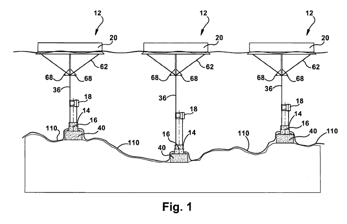
[0010] FIGURE 1 illustrates a view of an embodiment of a wave energy recovery
system.
[0011] FIGURE 2 is a schematic view of an embodiment of a wave energy recovery
system.
[0012] FIGURE 3 is a schematic illustration of another embodiment of a wave
energy
3
CA 02729033 2010-12-22
WO 2009/140615 PCT/US2009/044174
recovery system.
[0013] FIGURE 4 is a side cross-sectional view of a platform, generator, and
drum
mechanism of the wave energy recovery system of FIGURE 1.
[0014] FIGURE 5 is a side cross-sectional view of the drum mechanism and
generator of
FIGURE 4.
[0015] FIGURE 6 is a side view of the drum mechanism of the wave energy
recovery
system of FIGURE 1.
[0016] FIGURE 7 is a magnified view of the drum mechanism of FIGURE 4.
[0017] FIGURE 8 is a magnified view of a clutch of the drum mechanism of
FIGURE 7.
[0018] FIGURE 9 is a top view of the drum mechanism and guide plates.
[0019] FIGURE 10 is a top view of the guide plates of FIGURE 9.
[0020] FIGURE 11 is a side view of the generator.
[0021] FIGURE 12 is a rear view of the generator and platform of the wave
energy
recovery system of FIGURE 4.
[0022] FIGURE 13 is a front view of an oil pump of the wave energy recovery
system of
FIGURE 4.
[0023] FIGURE 14 is a perspective view of a buoy.
[0024] FIGURE 15 is a side view of a buoy in accordance with the present
invention.
4
CA 02729033 2010-12-22
WO 2009/140615 PCT/US2009/044174
[0025] FIGURE 16 is a top view of a buoy.
[0026] FIGURE 17 is another side view of the buoy of FIGURE 16.
[0027] FIGURE 18 is a side view of the buoy of FIGURE 14.
[0028] FIGURE 19 is a close up side view of the buoy of FIGURE 18 without
paddles.
[0029] FIGURES 20A and 20B are views of a retracting buoy.
[0030] FIGURE 21A is a close up perspective view of a paddle mechanism of
FIGURE
14.
[0031] FIGURE 21B is a close up side view of an alternative paddle mechanism.
[0032] FIGURE 22 is a schematic view of a valve and cylinder system.
[0033] FIGURE 23 is a side cross sectional view of a valve.
[0034] FIGURE 24 is a side cross sectional view of a return tank for the valve
of
FIGURE 23.
[0035] FIGURE 25 is a perspective view of a valve of FIGURE 23.
[0036] FIGURE 26 is a perspective view of the return tank of FIGURE 24.
[0037] FIGURE 27 illustrates a schematic illustration of an alternative
embodiment of a
wave energy recovery system.
[0038] FIGURES 28 and 29 illustrate detailed views of the wave energy recovery
system
of FIGURE 27.
CA 02729033 2010-12-22
WO 2009/140615 PCT/US2009/044174
[0039] FIGURE 30 illustrates a view of an alternative embodiment of a wave
energy
recovery system.
[0040] FIGURE 31 illustrates a manifold for use with a buoy of the wave energy
recovery system.
[0041] FIGURE 32 illustrates a check valve of a pedal compression mechanism
for use
with a buoy of the wave energy recovery system.
[0042] FIGURE 33 illustrates a view of an alternative embodiment of a
pneumatic
system for the wave energy recovery system.
DETAILED DESCRIPTION
[0043] While the present invention is disclosed with reference to the
embodiments
described herein, it should be clear that the present invention should not be
limited to
such embodiments. Therefore, the description of the embodiments herein is only
illustrative of the present invention and should not limit the scope of the
invention as
claimed.
[0044] A wave energy recovery system, as described herein and illustrated in
FIGURES
1-33, converts the energy of sea or ocean waves or other such water waves into
usable
mechanical and electrical energy. Apparatus and methods may be arranged such
that the
vertical pulse motion of waves of any magnitude and frequency may be converted
to
other types of motion such as, for example, linear or rotational motion. The
mechanical
energy of this resulting motion may be arranged to drive gearboxes, motors,
pumps,
various types of generators, or the like so as to generate energy, such as
electrical power.
6
CA 02729033 2010-12-22
WO 2009/140615 PCT/US2009/044174
[0045] In an embodiment, the vertical pulse motion of a wave may be translated
to a
buoy 20 floating at or near the surface of a body of water to vertically
displace the buoy
20. The vertical displacement of the buoy 20 may be translated to linear
motion of a
cable that is coupled to the buoy 20. The cable may be wrapped around a pulley
or drum
50, and the linear motion of the cable may be translated to rotational motion
of the pulley
or drum 50 to drive a generator 14, thereby capable of generating electric
power. The
generator 14 may be of any appropriate type, such as an alternating current
(AC)
permanent magnet generator. In addition, a plurality of motion translating
assemblies 12
may be arranged in series or parallel. The system 10 is capable of operating
without a
gearbox, as there is no switching of gears, with the drums 50, 52 and use of a
gearbox
may decrease the efficiency of the generator 14.
[0046] The AC permanent magnet generator 14 may be coupled to a rectifier to
convert
the alternating current (AC) produced by the generator 14 to a direct current
(DC). The
rectifier may be coupled to a voltage converter to generate a consistent DC
current that
may be used as a final source of electricity or to be converted back to AC
current and
delivered to a power generation grid. As used herein, the term "coupled" means
directly
or indirectly connected in a mechanical, electrical, or other such manner.
[00471 FIGURE 1 illustrates a wave energy recovery system 10. The system 10
may
comprise a motion translating assembly 12, a generator 14, a shaft 16, and a
platform 40.
The system 10 may be positioned at any appropriate location on the floor of
the ocean or
other body of water and may be positioned relatively close to shore. The
system 10 may
be arranged so as to generate electrical power and deliver that electrical
power to shore.
As will be further described below, the motion translating assembly 12 may
translate the
7
CA 02729033 2010-12-22
WO 2009/140615 PCT/US2009/044174
vertical pulse motion of a wave to rotational motion of the shaft 16, and such
rotational
motion of the shaft 16 may drive the generator 14.
[0048] In an exemplary embodiment illustrated in FIGURE 1, each motion
translating
assembly 12 may be arranged to drive a shaft 16 attached to a generator 14
independently
connected to and dedicated to that assembly 12. The vertical motion of the
main buoy 20
may be translated to rotational motion to rotate a shaft 16 that is coupled to
and drives the
generator 14 so as to produce electrical power.
[0049] As an alternative, a plurality of motion translating assemblies 12 may
be coupled
to a shaft to drive the generator, which may be located adjacent to the motion
translating
assembly 12 that is closest to the shore, as illustrated in FIGURE 30. In such
an
arrangement, it would be preferable that the shaft 16 only rotate in one
direction. As
multiple motion translating assemblies 12 assist in rotating the shaft 16,
limiting the shaft
16 to only one direction of rotation may allow the assembles 12 to cooperate
in driving
the generator 14. The coupling of numerous motion translating assemblies 12 to
one
generator may provide for a continuous rotation of the shaft 16 and an
efficient method of
driving the generator 14.
[0050] The generated electrical power may be delivered to shore, either for
immediate
use or to feed into a power distribution grid. As an alternative, the system
10 may be
arranged so as to generate electrical power and to utilize and store that
electrical power
locally on the system 10 to drive devices on the system 10 or near the system
10.
[0051] With further reference to FIGURE 1, a motion translating assembly 12
may
include a main buoy or float 20, a retracting buoy or float 18, and a main
cable 36. The
8
CA 02729033 2010-12-22
WO 2009/140615 PCT/US2009/044174
main cable 36 may be coupled on one end to the main buoy 20, coupled on the
other end
to the retracting buoy 18, and wrapped around the drum 52. As an alternative,
each drum
50, 52 may have its own dedicated cable 36, 38. In addition, each dedicated
cable 36, 38
may be coupled to its own dedicated buoy 18, 20. For example, the main cable
36 may
be coupled to the main buoy 20 and the drum 50, and the other cable 38 may be
coupled
to the retracting buoy 18 and drum 52, so that when one drum 50 turns in a
first direction,
such as clockwise, for example, the other drum 52 may turn in the same or an
opposite
direction, such as counterclockwise, for example.
[0052] While the motion translating assembly 12 and the ability to rotate is
discussed in
terms of utilizing drums 50, 52, it is to be understood that any appropriate
type of rotating
mechanism or apparatus may be utilized, such as pulleys (not shown), for
example. If
pulleys are utilized, they may be located within a pulley housing (not shown).
As an
alternative embodiment, the main cable 36 may be coupled on one end to the
main buoy
20, coupled on the other end to the retracting buoy 18, and wrapped around an
oscillating
pulley (not shown) that may be located within a pulley housing.
[0053] The buoys 18 and 20 may be arranged such that, as a wave engages the
main buoy
20, the main buoy 20 may be displaced vertically upward (i.e., rises relative
to the ocean
floor) and the cable 36 rotates the drum 50 in a clockwise rotation. As the
wave passes
the main buoy 20, the main buoy 20 may be displaced vertically downward (i.e.,
falls
relative to the ocean floor), the retracting buoy 18 rises to remove any slack
from the
cable 38, and the drum 52 rotates counterclockwise. Thus, as waves pass the
main buoy
20, vertical displacement of the main buoy 20 due to passing waves is
transformed into
linear motion of the main cable 36 and rotational motion of the drums 50, 52.
9
CA 02729033 2010-12-22
WO 2009/140615 PCT/US2009/044174
[0054] Although the cables 36, 38, buoys 20, 18 and drums 50, 52 have been
described
as being coupled in various ways, it will be readily understood by those
skilled in the art
that any number of additional arrangements may be utilized to convert vertical
motion of
the main buoy 20 to rotational motion, and should not be limited to those
arrangements
described herein.
[0055] The drums 50, 52 may be coupled to the shaft 16 such that rotational
motion of
the drums 50, 52 translates to rotational motion of the shaft 16. The shaft 16
may be
coupled to the generator 14 such that rotational motion of the shaft 16
translates to
rotational motion of the generator 14. The generator 14 may utilize such
rotational
motion to generate energy, such as electrical power. As the generator 14
generates
electrical power, the power may be delivered to the shore through a power
cable 110
attached to the generator 14.
[0056] The drums 50, 52 may drive the shaft 16 that drives the generator 14 to
create
electrical power. The inner drum 50 may operate the main buoy 20. The outer
drum 52
may operate the counter buoy 18. The drums 50, 52 may be of any appropriate
shape or
size, such as of a substantially conical shape, cylindrical shape, or the
like. If of a conical
shape, the drums 50, 52 may be wrapped with the cable or wire 36, 38 all the
way up and
around the incline of the cone shape. The conical shape may allow the drums
50, 52 to
rotate via a linear graduation, thereby providing a linear power graduation.
Thus, the
drums 50, 52 may spin at low rpms and, for example, may be prevented from
rotating
more than sixty (60) turns. Linear graduation may be achieved by providing the
same
distance between each step or location where the wire 36 or 38 is placed or
wrapped on
the drum 50 or 52. However, as an alternative, the system 10 may utilize a non-
linear
CA 02729033 2010-12-22
WO 2009/140615 PCT/US2009/044174
graduation.
[0057] The system 10 also may utilize a standard hydraulic clutch 106. For
example,
when the drums 50, 52 spin at or near 60 RPMs, the clutch 106 may be activated
to slow
movement of the drums 50, 52. As is well known in the art, the clutch 106 may
operate
due to frictional engagement of a clutch plate and a flywheel. The flywheel
may be a
large steel or aluminum "disc," that may be bolted to the driveshaft 16. The
flywheel
may act as a balancer for the generator 14, dampen vibrations, and provide a
smooth-
machined "friction" surface that the clutch 106 can contact. The main function
of the
flywheel is to transfer engine torque from the engine to the transmission.
[0058] The clutch disc may be similar to a steel plate and covered with a
frictional
material that is located between the flywheel and the pressure plate. In the
center of the
disc is the hub, which is designed to fit over the shaft 16. When the clutch
106 is
engaged, the disc may be "squeezed" between the flywheel and pressure plate,
and power
from the drum 52 may be transmitted by the disc's hub to the input shaft of
the
transmission.
[0059] The pressure plate may be a spring-loaded "clamp," which may be bolted
to the
flywheel. It may include a sheet metal cover, release springs, a metal
pressure ring that
provides a friction surface for the clutch disc, a thrust ring or fingers for
the release
bearing, and release levers. The release levers lighten the holding force of
the springs
when the clutch is disengaged. The springs may be of a diaphragm-type,
multiple coil
type, or other type as will be appreciated by one of ordinary skill in the
art. Some high-
performance pressure plates are "semi-centrifugal," meaning they may use small
weights
11
CA 02729033 2010-12-22
WO 2009/140615 PCT/US2009/044174
on the tips of the diaphragm springs to increase the clamping force as engine
revolutions
increase.
[0060] The "throw-out bearing" is the heart of clutch operation. When the
clutch pedal is
depressed, the throw-out bearing moves toward the flywheel, pushing in the
pressure
plate's release fingers and moving the pressure plate fingers or levers
against pressure
plate spring force. This action moves the pressure plate away from the clutch
disc, thus
interrupting power flow.
[0061] Mounted on an iron casting called a hub, the throw-out bearing slides
on a hollow
shaft at the front of the transmission housing. The clutch fork and connecting
linkage
convert the movement of the clutch pedal to the back and forth movement of the
clutch
throw-out bearing.
[0062] To disengage the clutch 106, the release bearing is moved toward the
flywheel by
the clutch fork. As the bearing contacts the pressure plate's release fingers,
it begins to
rotate with the pressure plate assembly. The release bearing continues to move
forward
and pressure on the release levers or fingers causes the force of the pressure
plate's spring
to move away from the clutch disc.
[0063] To engage the clutch 106, the clutch pedal is released and the release
bearing
moves away from the pressure plate. This action allows the pressure plate's
springs to
force against the clutch disc, engaging the clutch to the flywheel. Once the
clutch 106 is
fully engaged, the release bearing may be stationary and may prevent rotation
with
respect to the pressure plate.
12
CA 02729033 2010-12-22
WO 2009/140615 PCT/US2009/044174
[0064] A mechanical or hydraulic linkage may operate the clutch 106. A
hydraulic
clutch linkage may be similar to a mini hydraulic brake system. With a
hydraulic
mechanism, the clutch pedal arm operates a piston in the clutch master
cylinder. This
forces hydraulic fluid through a pipe to the clutch slave cylinder where
another piston
may operate the clutch disengagement mechanism. A master cylinder may be
attached to
the clutch pedal by an actuator rod, and the slave cylinder is connected to
the master
cylinder by high-pressure tubing. The slave cylinder is normally attached to a
bracket
next to the bell housing, so that it may move the clutch release fork
directly.
[0065] Similar to depressing the brake pedal on your car, depressing the
clutch pedal may
push a plunger into the bore of the master cylinder. A valve at the end of the
master
cylinder bore closes the port to the fluid reservoir, and the movement of the
plunger
forces fluid from the master cylinder through the tubing to the slave
cylinder. Since the
fluid is under pressure, it is capable of causing the piston of the slave
cylinder to move its
pushrod against the release fork and bearing, thus disengaging the clutch.
[0066] When the clutch pedal is released, the springs of the pressure plate
push the slave
cylinder's pushrod back, which forces the hydraulic fluid back into the master
cylinder.
One of the advantages of a hydraulic linkage is the physics: a small amount of
pedal force
can be used to manipulate what would normally be a heavy clutch with a shaft
and lever
linkage.
[0067] As an alternative, instead of utilizing a hydraulic clutch 106, the
system 10 may
utilize a sprag clutch (not shown) and flywheel. A sprag clutch is a one-way
freewheel
metal roller clutch. It resembles a roller bearing with rollers shaped like a
figure eight
13
CA 02729033 2010-12-22
WO 2009/140615 PCT/US2009/044174
and cocked with a spring. When the unit rotates in one direction, the rollers
stand up and
bind because of friction, and when the unit is rotated in the opposite
direction, the rollers
slip or freewheel. The process of changing up gears involves preparing for the
change by
releasing a clutch that prevents the transmission from turning faster than the
gear that it is
currently in and engaging the sprag such that it is freewheeling. The
gearchange occurs
by engaging the higher gear through the sprag to change from freewheeling to
driving.
[0068] Once the sprag has engaged drive in the higher gear, a clutch is
engaged to place
the transmission in that gear without the need for the sprag, which is then
disengaged. By
engaging and disengaging the various clutch packs within the transmission, one
sprag can
be used for all gearchanges. Depending on the relative rotating direction
between inner
and outer ring the clutch either transmits a friction-driven moment or
detaches drive end
and output end. It is to be understood that all roller bearings may be made
out of any
appropriate type of material, such as a synthetic composite.
[0069] As shown in FIGURES 4, 5, 9 and 10, the system 10 may also include a
guide
plate 54. There may be any appropriate number of guide plates 54, but
preferably there is
the number of guide plates 54 as drums. In addition, the guide plates 54 may
be of any
appropriate shape and size, but are preferably of a rectangular shape and of a
size
equivalent to that of the angled portion of the conical drums 50, 52. As
illustrated in
FIGURE 10, the guide plates 54 may include an end portion 53 and a guide rail
55.
Preferably, there are two end portions 53 and two guide rails 55, but it is to
be understood
that there may be any appropriate number of end portions 53 and guide rails
55. The end
portions 53 may be located at either end of the individual guide rails 55 to
maintain the
guide rails 55 in the appropriate spaced relation to one another.
14
CA 02729033 2010-12-22
WO 2009/140615 PCT/US2009/044174
[0070] The rectangular guide plates 54 may guide the wires 36, 38 onto the
conical
drums 50, 52. The guide plates 54 may be bolted to the drum housing 56, where
there
may be one guide plate 54 for each drum 50, 52. The guide plates 54 guide the
wires 36,
38 onto the appropriate step or location of the respective drum 50, 52. The
guide plates
54 may be attached to the drum housing 56 at any appropriate location or
angle, but are
preferably located parallel to the platform 40 and above the drums 50, 52 near
the top of
the housing 56. The guide plates 54 are also preferably located at an angle
that is similar
to the outer conical shape of the drums 50, 52, as shown in FIGURE 9.
[0071] With reference to FIGURES 4, 7, and 13, the wave energy recovery system
10
may also include an oil pump 112. The oil pump 112 may be operated from and
run off
of the driveshaft 16. The oil pump 112 may include a piston 114, a piston ball
116, and a
plurality of petals 118, as can be best seen in FIGURE 13. As the shaft 16
spins, the
petals 118 spin around, in a manner similar to a fan, for example, and push
the piston ball
116 up and down, thereby moving the piston 114 up and down. Thus, the oil may
be
pressurized and sent through the system 10 due to this action of the piston
114.
[0072] As shown in FIGURE 4, the generator 14 may be located on top of the
platform
40. Preferably the generator 14 is located towards one end of the platform 40
and the
drums 50, 52 are located toward the other end of the platform 40. Positioning
the
generator 14 on the seabed surrounds the generator 14 with water, which cools
the
generator 14 as it generates electric power. As generators 14 typically give
off heat,
providing a readily available method of cooling the generator 14 may increase
the
efficiency of the generator 14.
CA 02729033 2010-12-22
WO 2009/140615 PCT/US2009/044174
[0073] In addition, the wave energy recovery system 10 may also include a
radiator or
coolant system 108, as shown in FIGURES 11 and 12. The radiator 108 may be of
any
appropriate type. As the drums 50, 52 spin faster, the oil in the generator 14
can become
very hot. As the oil is passed through the generator 14, the radiator 108
cools the oil, and
then the oil may proceed back through the system 10 to the oil pump 16 to
start its
journey over.
[0074] As discussed above, each motion translating assembly 12 may be secured
to a
support platform 40 to maintain a static position with respect to the seabed.
With
reference to FIGURES 4 and 12, in an exemplary embodiment, the platform or
base 40
may be constructed of concrete with a plurality of steel reinforcement bars or
rebar 42
located throughout the platform 40 to aid in reinforcing the concrete platform
40.
Preferably, the platforms 40 may be moveable from one location to another when
it is
desired to move the platform 40, but stable and stationary enough the
remainder of the
time so that they do not shift once placed on the ocean or seabed floor.
[0075] Thus, the platform 40 preferably has enough mass to maintain its
position on the
seabed and resist movement due to tides, thrust from the main buoy 20, storms,
or other
inclement weather. The platform may be of any appropriate shape and size,
however, the
support platform 40 is preferably a rectangular slab of concrete measuring ten
feet in
width, eight feet in depth, and four feet in height. Such a concrete slab may
weigh
approximately twenty-five tons and can withstand substantial forces without
moving.
[0076] The platform 40 may also include diamond shaped pockets 44 on the
underside of
the platform 40 as well as airways 46, 48 throughout the platform 40. The
diamond
16
CA 02729033 2010-12-22
WO 2009/140615 PCT/US2009/044174
shaped pockets 44, which are approximately the shape of pyramids, may also be
made
out of cement. When the diamonds 44 are in contact with the sand, mud, etc. of
the
ocean or sea floor, the diamonds 44 may create suction cups that may prevent
the base 40
from being able to pull away from the floor. The move the base 40, there may
be vertical
airways 48 within the base 40. When it is desired to move the platform 40,
pressurized
air is pushed through the horizontal side airway tube 46, the air is then
pushed through
airways 48 and out through the intersection of the diamond edges 44 of the
base 40 that
breaks the suction via the internal airways 46, 48.
[0077] The plurality of motion translating assemblies 12 may be arranged in
any
appropriate location or manner away from the shoreline, as illustrated in
FIGURES 1-3.
In an embodiment, the plurality of motion translating assemblies 12 may extend
diagonally from the shoreline at any appropriate angle, such as an
approximately 45-
degree angle. In addition, the system 10 may include any appropriate number of
assemblies 12, such as approximately thirty motion-translating assemblies 12.
The
assemblies 12 may be spaced at any appropriate distance from one another, such
as being
spaced approximately 30 feet apart. Such an arrangement generally results in
each
incoming wave raising and lowering each main buoy 20 at a different point in
time.
[0078] As a wave progresses towards the shoreline, it may first encounter the
motion
translating assembly 12 located farthest off shore and raises and then lowers
the
translating assembly's 12 main buoy 20. Over time, the wave progresses through
the
plurality of assemblies 12 until it reaches the assembly 12 closest to the
shore. Such an
arrangement may be beneficial in that any single wave will not raise and lower
the
plurality of main buoys 20 at the same point in time, but will raise the
plurality of main
17
CA 02729033 2010-12-22
WO 2009/140615 PCT/US2009/044174
buoys 20 over a period of time. The raising of main buoys 20 over time as the
wave
progresses towards the shoreline causes different motion translating
assemblies 12 to
rotate the shaft 16 at different times, resulting in constant rotation of the
shaft 16 at a
generally constant speed and thus providing a constant supply of energy to the
power
grid.
[0079] An embodiment of a main buoy 20 for use with a wave energy recovery
system
is illustrated in FIGURES 14-20. The buoy 20 may include numerous features and
sub-systems that improve the durability or service life of the system 10. In
addition, the
buoy 20 may include numerous features and subsystems for enhancing the overall
efficiency and functionality of the system 10.
[0080] For example, the buoy 20 may include numerous features that provide for
the
dynamic positioning of the buoy 20 relative to the surface of the water. Minor
adjustments in the position of the buoy 20 may increase the efficiency of the
system 10 as
the height and frequency of waves change. When violent storms or other such
hazards
are present, the buoy 20 may be selectively submerged below the surface of the
water so
as to reduce or eliminate damage to the buoy 20 or other system components.
Once the
storm passes or other such hazards subside, the buoy 20 may be returned to an
operative
position at or near the surface of the water.
[0081] The buoy 20 may be of any appropriate shape and size and may be made
out of
any appropriate material. The buoy 20 may be constructed from a metal frame
and an
aluminum skin. however, the buoys 20 may be constructed out of any appropriate
material that allows the buoy 20 to float and rise and fall as waves pass. The
main buoy
18
CA 02729033 2010-12-22
WO 2009/140615 PCT/US2009/044174
20 may be of any appropriate size, such as the approximate size of an
automobile, for
example. The buoy 20 may be unable to fall or tip over in the water due to its
shape and
size. The shape of the main buoy 20 may be of any appropriate shape or
configuration
capable of floating, such as a generally rectangular body, cylindrical body,
or the like.
While shown as of generally rectangular shape in the FIGURES, it is to be
understood
that this is not meant to be limiting in any way, and is for illustrative
purposes only.
[0082] As illustrated in FIGURES 1, 15, and 17, the buoy 20 may be equipped
with a
plurality of connector cables 62 that are coupled at one end to the buoy 20
and are
coupled at the other end to the main cable 36. The connector cables 62 may be
coupled
to the buoy 20 by any appropriate means. For example, the connector cables 62
may be
coupled via connector rings (not shown), pistons (not shown), pivot
connection, or the
like. If the connector cables 62 are coupled to the buoy 20 by pistons, the
pistons may be
of any appropriate type, such as pneumatic pistons.
[0083] The pistons may be pressurized or depressurized to better position the
buoy 20
with respect to the surface of the water. In one embodiment, a piston may be
pressurized
so as to affect the angel at which the buoy 20 is positioned with respect to
the surface of
the water. Placing the buoy 20 at an angle may provide for greater wave impact
on the
buoy 20 so as to increase the vertical displacement of the buoy 20, thus
increasing the
energy recovered by the buoy 20.
[0084] For example, the connector cables 62 may be coupled to the buoy 20 by a
pivot
connection 60 through which the buoy 20 is connected to the main cable 36.
Three
connector cables 62 may be attached to the pivot connection 60 on one end and
attached
19
CA 02729033 2010-12-22
WO 2009/140615 PCT/US2009/044174
to a pivot connection 60 on the other end. There may be a common ring 64
located at the
bottom of a rigid member 66. The main cable 36 may be attached to the common
ring 64
on one end and wrapped around the drums 50, 52 as previously described. In a
preferred
embodiment, the main cable 36 and the connector cables 62 are approximately
3/8 inch in
diameter, with the connector cables 62 approximately 10 to 15 feet in length
and the main
cable 36 approximately 100 to 200 feet in length.
[0085] Referring again to FIGURES 1, 15, and 17, a rigid member 66, such as a
pipe,
may extend downward from the bottom 76 of the buoy 20, and at least one keel
member
68 is attached to the pipe 66. Optionally, multiple keel members 68 may be
attached to
the pipe 66, but preferably, there are three keel members 68 attached to the
pipe 66, each
120 degrees apart. The pipe 66 is preferably ten feet in length, and the keel
members 68
are triangular shaped and three feet high and three feet wide. As a wave
passes the buoy
20 the turbulence in the water is near the surface. The keel members 68 may be
located
at any appropriate position.
[0086] Positioning the keel members 68 approximately below the surface of the
water,
such as ten feet below the surface, for example, places avoids the turbulence
of the wave.
Such an arrangement provides stability to the buoy 20 and eliminates or
reduces lateral
movement, wobbling or rocking of the buoy 20. The elimination of such movement
increases the vertical displacement of the buoy 20 and allows recovery of an
increased
percentage of a wave's energy.
[0087] A particular shape of the main buoy 20, such as a rectangular or
cylindrical shape,
for example, may produce greater thrust in the motion translating assemblies
12 and
CA 02729033 2010-12-22
WO 2009/140615 PCT/US2009/044174
produce greater rotational motion of the shaft 16. A rectangular component
placed in
rough waters has a tendency to turn such that its longer vertical surface
faces the
incoming waves. By offering a greater surface area to incoming waves, the buoy
20 may
catch more of the wave, thereby providing more thrust to the main cable 36 as
the buoy
20 is moved upward by a passing wave. The rectangular buoy 20 may be of any
appropriate size, such as thirty feet wide, ten feet deep, and five feet high,
for example.
[0088] The retracting buoy 18, as best shown in FIGURES 1, 20A, and 20B, may
be of
any appropriate size and shape and may be made out of any appropriate
material, such as
being constructed from aluminum and being cylindrically shaped. The retracting
buoy 18
may also include a guide sleeve 58. Similar to the main buoy 20, the
retracting buoy 18
may also be equipped with a pair of valves 90, 92, such as an air inlet valve
to intake air
and expel water ballast, and a water inlet valve to intake water to increase
water ballast.
The retracting buoy 18 may also include a manhole or hatch 120 to give access
to the
inside of the retracting buoy 18 in case any repairs may need to be made. The
bottom of
the retracting buoy 18 may be attached to a cable 38 by any appropriate means,
such as a
ring or fastener.
[0089] The guide sleeve 58 may be attached to the side of the retracting buoy
18. The
guide sleeve 58 may be arranged to slide along the cable 36 to maintain a
controlled
reciprocating motion as a wave progresses past the main buoy 20. In an
embodiment, the
retracting buoy 18 may be approximately 16 inches in diameter and 24 inches in
height.
[0090] With respect to the cost of building traditional power plants, a wave
energy
recovery system 10 is very inexpensive to build and install. To install a
system 10,
21
CA 02729033 2010-12-22
WO 2009/140615 PCT/US2009/044174
components of the system 10 may be loaded onto pontoons or other such floating
platforms. The pontoons may be evenly spaced along the surface of the water.
The
spacing of the pontoons may be approximately equal to the desired operative
distance
between installed support platforms 40 along the seabed. These assembled
support
platforms 40 may be lowered into position on the seabed from the pontoons,
using any
conventional means, such as chains or cables.
[0091] Once the drums 50, 52 are coupled to the shaft 16, the cables 36 and 38
may be
wrapped around each drum 50 and 52 respectively, and a retracting buoy 18 may
be
attached to one end of the cable and the guide sleeve 58 installed along the
cable. The
free end of the main cable 36 may be attached to the common ring 64 and the
length of
the main cable 36 properly adjusted.
[0092] Each motion translating assembly 12 may be arranged to drive a shaft 16
attached
to a generator 14 dedicated to that assembly 12. The motion translating
assemblies 12 are
arranged to drive dedicated generators 14 coupled to each support platform 40.
However, a permanent magnet generator 14 is attached to each support platform
40. The
vertical motion of the main buoy 20 is translated to rotational motion to
rotate a
driveshaft 16. The driveshaft 16 is coupled to and drives the generator 14,
which
produces electric power. The generated electric power can be delivered to
shore, either
for immediate use or to feed into a power distribution grid. Optionally, the
electric power
can be stored on the support platform 40 to be subsequently delivered to
shore.
[0093] In an alternative embodiment, the electric power may be stored on the
support
platform 40 by coupling the generator 14 to a supercapacitor (not shown).
22
CA 02729033 2010-12-22
WO 2009/140615 PCT/US2009/044174
Supercapacitors offer relatively high cycle lives, having the capacity to
cycle millions of
times before failing; low impedance; rapid charging; and no loss of capability
with
overcharging. A power cable 110 may be attached to each supercapacitor to
deliver
stored electric power to shore. As a wave passes the motion translating
assemblies 12,
some assemblies produce electric power, while others are momentarily idle. A
programmable logic control device may optionally be incorporated into the
system to
control the generators 14 and other system components to delivery a consistent
electrical
current to the shore.
[0094] The driveshafts 16 may be arranged to only rotate in one direction or
may
optionally be arranged to rotate in both clockwise and counterclockwise
directions. An
AC permanent magnet generator may be arranged to generate electric power
regardless of
the direction the driveshaft 16 rotates. Generators 14 may also be arranged to
eliminate
any need for a gearbox when generating electric power. The system 10 may be
arranged
such that each dedicated generator 14 has a dedicated power cable 110 to
deliver electric
power to shore. The electric power generated by the plurality of generators 14
may be
accumulated on shore and delivered to a power distribution grid.
[0095] The use of dedicated generators 14 secured to each support platform 40
allows for
easy installation of the wave energy recovery system. The wave energy recovery
system
may be secured to the ocean floor by a support platform 40. As discussed
above, the
support platform 40 may be a concrete slab with enough mass to maintain its
position on
the ocean floor and resist movement due to tides, thrust from the main buoy
20, storms,
or other inclement weather.
23
CA 02729033 2010-12-22
WO 2009/140615 PCT/US2009/044174
[0096] As illustrated in FIGURE 2, support platforms 40 may be placed
randomly,
without concern for the positioning of adjacent platforms 40. Each motion
translating
assembly 12 and dedicated generator 14 is self-sufficient and does not rely on
adjacent
assemblies 12. Flexible power cables 110 allow a generator 14 or
supercapacitor to
deliver electric power to shore from nearly any location on the seabed, either
in series or
in parallel.
[0097] As illustrated in FIGURES 14-20, the buoy 20 includes a generally
hollow hull or
body 22. The body 22 optionally may be internally supported by beams (not
shown) or
others such structural members. The body 22 may be arranged to include a
number of
generally flat surfaces such as, for example, a pair of top surfaces 24, a
pair of side
surfaces 26, a pair of front surfaces 28, a pair of back surfaces 30, and a
pair of bottom
surfaces 32.
[0098] The pair of top surfaces 24 may be arranged at an angle to one another
so that a
peak is formed between the pair of top surfaces 24. Such a peak will encourage
rain or
other such precipitation to run off the top surfaces 24, thus discouraging the
pooling of
water on the top surfaces 24. The side 26, front 28, and back 30 surfaces of
the buoy 20
each may be arranged at an angle with respect to a vertical plane.
[0099] Such an arrangement may limit lateral movement of the buoy 20 and
enhance
vertical movement of the buoy 20 as waves impact the front, back, and sides of
the buoy
20. For example, as a wave impacts the front, back, or sides of the buoy 20,
the angled
surface of the buoy 20 causes a portion of the energy of the wave to encourage
the buoy
20 to be displaced vertically.
24
CA 02729033 2010-12-22
WO 2009/140615 PCT/US2009/044174
[00100] In another example, as a wave washes over the buoy 20, the portion of
the
wave washing over the buoy 20 may commonly impact the opposing side of the
buoy 20.
When the side is positioned at an angle to a vertical plane, the portion of
the wave
washing over the buoy 20 may encourage the buoy 20 downward. In addition, the
wave
washing over the buoy 20 encourages the buoy 20 to move laterally back toward
the
direction from which the waves originated, thus offsetting the lateral
movement of the
buoy 20 due to the initial impact of the wave. Upon studying the description
and
FIGURES provided herein, it will be readily understood by those skilled in the
art that
arranging the side, front, and back surfaces at an angle relative to a
vertical plane may
facilitate the vertical movement of the buoy 20 and decreases the lateral
movement of the
buoy 20.
[00101] The pair of bottom surfaces 32 may be arranged at an angle to one
another
so as to form a generally concave bottom. Such an arrangement may promote the
stability of the buoy 20 by reducing or eliminating wobbling or other such
oscillation of
the buoy 20 as waves impact the buoy 20. The buoy 20 may also include a skirt
34
extending from the bottom surfaces 32 of the buoy 20. The skirt 34 may be of
any
appropriate shape, size and material. The positioning and shape of the skirt
34 may
further reduce or eliminate any undesired lateral movement, wobbling, and
rocking of the
buoy 20. The shape of the skirt 34, in cooperation with the downward forces
produced
by the main cable 36, may hold the buoy 20 level on the surface of the water
as a wave
passes. As the wave displaces the buoy 20 upward, the buoy 20 remains level,
thus
reducing or eliminating any undesired lateral movement, wobbling, or rocking.
Maximizing the vertical movement of the buoy 20 also maximizes the energy
recovered
CA 02729033 2010-12-22
WO 2009/140615 PCT/US2009/044174
from a wave.
[00102] The main buoy 20 may further be equipped with valves, such as an air
inlet valve 90 and a water inlet valve 92. The buoy 20 may also include valves
90, 92
located in the top and bottom sides 24, 32 of the buoy 20. There may be any
appropriate
number of valves 90, 92, but there are preferably six (6) valves 90 located on
the top 24
of the buoy 20 and six (6) valves 92 located on the bottom 32 of the buoy 20.
The top
valves 90 allow air in to raise the buoy 20 and the bottom valves 92 allow
water in to sink
the buoy 20, thereby steadying the buoy 20 with ballast. The buoy 20 is
intended to float
near the top of the water in order to receive the effect of the waves. The
water within the
buoy 20 may be kept at any appropriate level, but is preferably maintained at
about 1/8"
around the bottom of the buoy 20. The air and water levels from the valves
within the
buoy 20 may be electronically regulated.
[00103] The valves 90, 92 may be operated by any appropriate means, but are
preferably remotely operated. The valves 90 and 92 may be remotely controlled
to take
in water through the water inlet valve 92 for additional ballast to stabilize
the floating
position of the buoy 20, or to take in pressurized air through the air inlet
valve 90 to expel
water and reduce water ballast in the buoy 20. The valves 90, 92 may be
arranged such
that the buoy 20 may take on enough water ballast to completely submerge the
buoy 20.
[00104] The buoy 20 may also include a series of valves 90, 92 provided to
allow
fluids to enter and exit the hull 22 of the buoy 20. In one embodiment, six
valves 90 are
located along the top surfaces 24 of the buoy 20, and six valves 92 are
located along the
bottom surfaces 32 of the buoy 20. Such an arrangement may provide for the
intake and
26
CA 02729033 2010-12-22
WO 2009/140615 PCT/US2009/044174
expulsion of fluids from the hull 22 of the buoy 20.
[00105] In one example, the topside valves 90 may be arranged so as to allow
atmospheric air into the hull 22 of the buoy 20 and may be arranged so as to
allow the
expulsion of atmospheric air from the hull 22 of the buoy 20. In another
example, the
bottom-side valves 92 may be arranged so as to allow water from the
surrounding body
of water into the hull 22 of the buoy 20 and may be arranged to allow for the
expulsion of
water from the hull 22 into the surrounding body of water.
[00106] Through such arrangements, the amount of water in the hull 22 may be
controlled and, thus, the amount of ballast in the hull 22 may be controlled.
The amount
of ballast in the hull 22 may be used to control the location of the buoy 20
with respect to
the surface of the water. Controlling the location of the buoy 20 with respect
to the
surface of the water may allow the buoy 20 to be submerged to protect the buoy
20 from
inclement weather. Such control also may allow for precisely locating the buoy
20 with
respect to the surface of the water to increase the efficiency of energy
recovery from
passing waves.
[00107] Valves 90, 92 such as those described herein may be arranged to open
or
close through the application of mechanical forces on the valves 90, 92. In
one example,
the valves 90, 92 may be coupled to a spring 150 or other such biasing member
to
encourage the valves toward either an open or a closed position. In another
example, the
valves 90, 92 may be coupled to a pneumatic member, such as a pneumatic
cylinder, to
selectively encourage a valve into either an open or closed position. It will
be readily
understood from this description and accompanying illustrations that a valve
may be
27
CA 02729033 2010-12-22
WO 2009/140615 PCT/US2009/044174
coupled to both a biasing member and a pneumatic member to selectively open
and close
valves. In addition, it will be understood that other forces, such as gravity,
surrounding
environmental pressures, hydraulic pressure, and the like, may be utilized to
encourage a
valve into a desired position.
[00108] With regard to the surrounding environment being utilized to assist in
the
opening or closing of the valves 90, 92, in one example the buoy 20 may be
designed
such that fluid pressure from the surrounding body of water may be utilized to
encourage
a valve into an open or a closed position. Similarly, a buoy 20 may be
designed such that
pressure from the surrounding atmosphere may be utilized to encourage a valve
into an
open or a closed position. Such environmental forces may be accounted for in
the design
of valves, springs, pneumatic members, and the like so as to ensure the
formation of
effective valves.
[00109] In one embodiment, a pneumatic system 70 may be incorporated into a
buoy 20 to selectively open and close the valves 90, 92. The valves 90, 92 may
be
coupled on the outer edge of the body or hull 22 of the buoy 20. The pneumatic
system
may include air inlet and outlet valves 90, 92, a plunger valve 148 and a
return tank 144.
The plunger valve 148 may include a plunger 146, a spring 150, an air hole
152a, a piston
154a, and an inlet/outlet 156. The return tank 144 may include an air hole
152b and a
piston 154b. The air hole 152b of the return tank 144 may be in communication
with the
valve 90, 92.
[00110] For example, as shown in FIGURES 23 and 24, as the valve 92 pushes the
spring 150 down to open the plunger 146, air is pushed down and sent to the
return tank
28
CA 02729033 2010-12-22
WO 2009/140615 PCT/US2009/044174
144. The air sent to the return tank 144 pushes down the piston 154b thereby
creating a
pressurization of the tank, which may aid in closing the plunger 146 as the
displaced air
in the return tank 144 forces the piston 154b back to its original position,
as shown in
FIGURE 24.
[00111] The plunger valve 148 may be coupled to a source of pressurized gas
that
may selectively pressurize the plunger valve 148. The selection to pressurize
the valves
90, 92 may be driven by computer logic and controls located in any appropriate
place,
such as either on the buoy 20, near the buoy 20, or remotely from the buoy 20,
for
example. The spring 150 may be located within the approximate center of the
plunger
valve 148. The spring 150 may be of any appropriate type, but is preferably an
approximate seventy-pound (70 lb.) spring. The plunger 146 may face any
appropriate
direction, but preferably faces an outward direction.
[00112] In one embodiment, the pneumatic system may be arranged such that,
when the plunger valve 148 is pressurized, a bottom-side valve 92 is
encouraged into the
open position, as shown in FIGURE 23. Such an arrangement may facilitate the
filling of
the hull 22 with water from the surrounding body of water. Once the plunger
146 is in
the closed position, water may be prevented from entering the buoy 20.
[00113] As an alternative, as illustrated in FIGURE 33, pneumatic systems 70
may
be incorporated into a buoy 20 to selectively open and close the valves 90,
92. A
pneumatic system 70 may include a spring 72 and a pneumatic cylinder 74,
wherein each
pneumatic cylinder 74 may be coupled on one end to the door of a valve 90, 92
and may
be coupled on the other end to the body or hull 22 of the buoy 20. The
pneumatic
29
CA 02729033 2010-12-22
WO 2009/140615 PCT/US2009/044174
cylinder 74 may be coupled to a source of pressurized gas that may selectively
pressurize
the cylinder 74. The selection to pressurize the cylinder 74 may be driven by
computer
logic and controls located either on the buoy 20, near the buoy 20, or
remotely from the
buoy 20.
[001141 The pneumatic cylinder 74 may be arranged such that, when the cylinder
74 is pressurized, a bottom-side valve 92 is encouraged into the open
position. The spring
72 may be arranged such that the spring 72 encourages the bottom-side valve 92
into the
closed position to assist in closing the valve 92 when the cylinder is
selectively
depressurized or in the event that the pneumatic cylinder 74 or the logic
driving the
cylinder 74 fails. Such an arrangement may facilitate the filling of the hull
22 with water
from the surrounding body of water.
[001151 When a system operator or computer logic determines that it is
desirable
to submerge the buoy 20 due to inclement weather or other such hazard, one
method of
submerging the buoy 20 is to fill the hull 22 with enough water to overcome
the
buoyancy of the buoy 20, thereby submerging the buoy 20. As the bottom-side
valves 92
are commonly in contact with the body of water, the environmental pressures
tend to hold
the valves 92 in the closed position. Such environmental pressures, along with
the
arrangement of the spring 72, serve to seal the bottom-side valves 92 such
that the valves
92 normally resist water entering the hull 22. However, when it is desirable
to open the
valves 92 and allow water to enter the hull 22, the pneumatic cylinder 74 is
pressurized to
overcome the environmental pressures and the spring force to open the valves
92. When
sufficient water has entered the hull 56 to submerge the buoy 20 to its
desired depth, the
pneumatic cylinders 74 may be depressurized, and the spring 72 may return the
valve 92
CA 02729033 2010-12-22
WO 2009/140615 PCT/US2009/044174
to its closed position. The buoy 20 may include a depth meter (not shown) to
assist in
determining when the buoy 20 reaches the desired depth.
[00116] With further reference to FIGURE 33, the pneumatic cylinder 74 may be
arranged such that, when the cylinder 74 is pressurized, a topside valve 90 is
encouraged
into the closed position. The spring 72 may be arranged such that the spring
72 also
encourages the topside valve 90 into the closed position so that the valve
remains closed
when the cylinder 74 is selectively depressurized. Maintaining the valve 90 in
the closed
position may seal the hull 22 so that rain or other moisture is not permitted
to enter the
hull 22.
[00117] The closing of the topside valves 90 by pressurizing the cylinder 74
may
assist in facilitating the expulsion of water from the hull 22 through the
bottom-side
valves 64. When a system operator or computer logic determines it is desirable
to return
the buoy 20 from a submerged position to an operative position at the surface
of the
water, the buoy 20 may be raised by expelling water from the hull 22 back into
the
surrounding body of water so as to increase the buoyancy of the buoy 20.
[00118] One method of expelling water from the buoy 20 is to close and seal
the
topside valves 90, open the bottom-side valves 92, and pressurize the hull 22
such that
the water in the hull 22 flows out of the bottom-side valves 92 and back into
the
surrounding body of water. The cylinders 74 may be pressurized so as to apply
a
substantial force on the doors of the topside valves 90, thereby sealing the
valves 90, i.e.,
holding the valves 90 closed against the internal pressure building in the
hull 22 that is
used to expel the water.
[00119] Once the water is expelled from the hull 22, the cylinders 74 coupled
to
31
CA 02729033 2010-12-22
WO 2009/140615 PCT/US2009/044174
the topside valves 90 may be depressurized, and the springs 72 coupled to the
topside
valves 90 may apply a sufficient force to the door of the topside valve 90 to
maintain the
valve 90 in a closed position so as to keep unwanted moisture out of the hull
22. In
another embodiment, the springs 72 coupled to the topside valves 90 apply a
sufficient
force to maintain the valve 90 in a closed position, but also allow the valve
90 to serve as
a release valve that vents pressure that may develop in the hull 22 during the
operation of
the wave energy recovery system 10.
[00120] A complete submersion of the buoy 20 may be desirable to reduce or
eliminate damage to the buoys 20 or other system components when violent
storms or
other such hazards are present. Once a storm passes, the buoy 20 may take in
pressurized
air through the air inlet 90 to expel water ballast and return the buoy 20 to
its operative
position. Furthermore, the main buoy 20 may be adjustably raised or lowered
through the
intake and expulsion of water ballast to dynamically adjust the buoy 20
position in
response to changing wave conditions to maintain optimal operative positioning
for the
buoy 20.
[00121] Ballast is used to provide moment to resist the lateral forces on the
buoy
20. If the buoy 20 is insufficiently ballasted it will tend to tip, or heel,
excessively in high
winds. Heeling may occur when there is too much wind or water pressure to one
side,
thereby causing the buoy 20 to lean over to one side. In addition, too much
heel may
result in the buoy 20 flipping over or out of its preferred position in
relation to the waves.
Adding water ballast below the vertical center of gravity increases stability.
When the
buoy 20 heels, it must then lift the ballast clear of the water, at which
point it is obvious
that it does provide righting moment. One advantage of water ballast is that
it can be
32
CA 02729033 2010-12-22
WO 2009/140615 PCT/US2009/044174
dumped out by having a valve at the bottom of the ballast chamber, reducing
the weight
of the buoy 20, and then added back in by opening up the valves and letting
the water
flow in after the buoy 20 is back in its ideal position.
[00122] When a system operator or computer logic determines that it is
desirable
to submerge the buoy 20 due to inclement weather or other such hazard, one
method of
submerging the buoy 20 is to fill the hull 22 with enough water to overcome
the
buoyancy of the buoy 20, thereby submerging the buoy 20. As the bottom-side
valves 92
are commonly in contact with the body of water, the environmental pressures
may tend to
hold the valves 92 in the closed position. Such environmental pressures, along
with the
arrangement of the spring 150, serve to seal the bottom-side valves 92 such
that the
valves 92 normally resist water entering the hull 22.
[00123] However, when it is desirable to open the valves 92 and allow water to
enter the hull 22, the plunger valve 148 is pressurized to overcome the
environmental
pressures and the spring force to open the valves 92. When sufficient water
has entered
the hull 22 to submerge the buoy 20 to its desired depth, the plunger valves
148 may be
depressurized, and the spring 150 may return the valve 92 to its closed
position. The
buoy 20 may also include a depth meter (not shown) to assist in determining
when the
buoy 20 reaches the desired depth.
[00124] In one embodiment, a plunger valve 148 is arranged such that, when the
plunger valve 148 is pressurized, a topside valve 90 is encouraged into the
closed
position. The spring 150 may be arranged such that the spring 150 also
encourages the
topside valve 90 into the closed position so that the valve remains closed
when the
33
CA 02729033 2010-12-22
WO 2009/140615 PCT/US2009/044174
cylinder 74 is selectively depressurized. Maintaining the valve 90 in the
closed position
may seal the hull 22 so that rain or other moisture is not permitted to enter
the hull 22.
[00125] The closing of the topside valves 90 by pressurizing the plunger
valves
148 may assist in facilitating the expulsion of water from the hull 22 through
the bottom-
side valves 92. When a system operator or computer logic determines it is
desirable to
return the buoy 20 from a submerged position to an operative position at the
surface of
the water, the buoy 20 may be raised by expelling water from the hull 22 back
into the
surrounding body of water so as to increase the buoyancy of the buoy 20.
[00126] One method of expelling water from the buoy 20 is to close and seal
the
topside valves 90, open the bottom-side valves 92, and pressurize the hull 22
such that
the water in the hull 22 flows out of the bottom-side valves 92 and back into
the
surrounding body of water. The plunger valves 148 may be pressurized so as to
apply a
substantial force on the doors of the topside valves 90, thereby sealing the
valves 90, i.e.,
holding the valves 90 closed against the internal pressure building in the
hull 22 that is
used to expel the water.
[00127] Once the water is expelled from the hull 22, the plunger valves 148
coupled to the topside valves 90 may be depressurized, and the springs 150
coupled to the
topside valves 90 may apply a sufficient force to the door of the topside
valve 90 to
maintain the valve 90 in a closed position so as to keep unwanted moisture out
of the hull
22. In another embodiment, the springs 150 coupled to the topside valves 90
apply a
sufficient force to maintain the valve 90 in a closed position, but also allow
the valve 90
to serve as a release valve that vents pressure that may develop in the hull
22 during the
34
CA 02729033 2010-12-22
WO 2009/140615 PCT/US2009/044174
operation of the wave energy recovery system 10.
[00128] The methods of affecting buoyancy through intake and expulsion of
water
from the hull 22 described above may be used to either submerge or raise a
buoy 20 or
precisely position a buoy 20 at the surface of the water. Precise positioning
of a buoy 20
at the surface of the water may increase the efficiency of the system with
regard to
recovery of energy, safety, etc. Other methods of precise positioning of the
buoy 20 may
include the use of pressure chambers 76 located on the buoy 20. In addition,
it is also
preferable that the inside of the buoy 20 maintains a certain amount of
pressurized air.
Any appropriate amount of pressurized air may be used, such as maintaining a
pressure
of three psi within the buoy 20. Maintaining the buoy 20 full of pressurized
air may aid
in maintaining the buoyancy of the buoy 20.
[00129] The buoy 20 may also include at least one cylinder or tank 76, but
preferably six tanks located at any appropriate location on the buoy 20, but
preferably
located along an outer edge of the buoy 20. Five of the tanks 76 may include
ballast air
from the paddle mechanism 80. When the paddles 82, 84 move to stabilize the
buoy 20,
the paddles 82, 84 may push air into the ballast air tanks 76. The sixth and
last tank 76
may be a control tank that provides air that may be used to open and control
valves 90,
92.
[00130] As illustrated in FIGURE 19, a plurality of pressure chambers or tanks
76
may be distributed along the bottom side of the buoy 20. In one example, a
pressure
chamber 76 may be arranged as an elongated tube positioned in the hull 22 and
running
along the inner surface of the bottom side of the hull 22. Although pressure
chambers 76
CA 02729033 2010-12-22
WO 2009/140615 PCT/US2009/044174
are described and illustrated as running along the bottom side of the hull 22,
it will be
readily appreciated by those skilled in the art that pressure chambers may be
distributed
anywhere throughout the buoy 20. For example, pressure chambers may be located
along
the internal surfaces of the topside, as illustrated in FIGURE 33, along
internal surfaces
of the sides of the hull, or within structural members supporting the hull.
[00131] Pressurizing the pressure chambers 76 to different pressures may
control the
buoyancy of the buoy 20. Increasing the buoyancy will generally raise the
position of the
buoy 20 with respect to the surface of the water. Decreasing the buoyancy will
generally
lower the position of the buoy 20 with respect to the surface of the water. As
will be
subsequently discussed herein, mechanical systems attached to the buoy 20 may
be
utilized to pressurize the pressure chambers 76. Computer logic or system
operators may
determine that a change in the buoy's 20 position relative to the surface of
the water will
increase the efficiency of the system 10. The computer logic or system
operator then
may increase the pressure in the chambers 76 or may decrease the pressure in
the
chambers 76 so as to affect buoyancy and more optimally position the buoy 20.
[00132] The pressure chambers 76 may be further utilized as a source of
pressurized gas
to control other systems or functions of the buoy 20. In one example, the
pressure
chambers 76 may be used as a source of pressurized gas for pressurizing the
pneumatic
system 70 so as to move valves 90, 92 to open and closed positions, as
described herein.
In another example, pressurized gas in the pressure chambers 76 may be used so
as to
pressurize the hull 22 such that water is expelled from the hull 22 when it is
desirable to
return a submerged buoy 20 to the surface of the water.
36
CA 02729033 2010-12-22
WO 2009/140615 PCT/US2009/044174
[00133] The buoy 20 may further include at least one paddle mechanism 80. The
paddle mechanism(s) 80 may be located at any appropriate location on the buoy
20, but
preferably located on its side(s) 26. The paddle mechanisms 80 may help to
stabilize the
buoy 20 by keeping the largest face of the buoy 20 on the wave so that the
buoy 20 rises
and falls horizontally.
[00134] The paddle mechanisms 80 may include an inner paddle 82, and outer
paddle 84, and a main piston 86, and an adjustment piston 88. The pair of
paddle
members 82, 84 may be coupled by a hinge pin 94 such that the paddles 82, 84
may be
adjusted to positions at varying angles relative to one another. The paddle
mechanisms
80 may also pump air within the buoy 20 so that the buoy is filled with
pressurized air to
keep the buoy 20 stationary. Preferably, during operation of the system 10 the
buoy 20
should not move above eighteen feet due to the waves. The buoy 20 moves
approximately three to four feet up and down with the waves all the time.
[00135] The positioning and shape of the paddle mechanisms 80 also tend to
eliminate or reduce lateral movement, wobbling, and rocking of the buoy 20.
The shape
of the paddles 82, 84, in cooperation with the downward forces produced by the
main
cable 36 and connector cables 62, holds the buoy 20 level on the surface of
the water as a
wave passes. As the wave displaces the buoy 20 upward, the buoy 20 remains
level, thus
reducing or eliminating lateral movement, wobbling, and rocking. As described
above,
maximizing vertical movement also maximizes the energy recovered from a wave.
[00136] Mechanical systems attached to the buoy 20 may be utilized to
pressurize the
pressure chambers 76. One exemplary embodiment of such a mechanical system is
37
CA 02729033 2010-12-22
WO 2009/140615 PCT/US2009/044174
illustrated in FIGURE 21A. FIGURE 21A illustrates a paddle compression
mechanism
80 for pressurizing the pressure chambers 76 of the buoy 20. Each paddle
mechanism 80
may include an inner paddle flap 82 and an outer paddle flap 84. Each of the
paddle flaps
or members 82, 84 may be adjustable in order to achieve the maximum power from
each
wave. The paddle compression mechanism 80 utilizes mechanical movements caused
by
the interaction of the paddle mechanism 80 with waves in order to generate
pressure and
to deliver that pressure to the pressure chambers 76.
[00137] As discussed above, the inner paddle 82 may be connected to the buoy
20 by a
hinge pin 94 so that the inner paddle 82 may be adjusted to positions at
varying angles
relative to the side 26 of the buoy 20. The adjustment piston 88 is coupled to
both
paddles 82, 84 such that the expansion or contraction of the adjustment piston
88 controls
the positioning of the paddle members 82, 84 relative to each other. The
length of the
adjustment piston 88 may be rigidly set such that the relative position of the
paddles 82,
84 is rigid or otherwise static.
[00138] In one embodiment, the paddles 82, 84 may be positioned such that
inner paddle
82 is generally positioned at the surface of the water and parallel to the
surface of the
water. The outer paddle 84 is positioned above the surface of the water and at
an acute
angle to the surface of the water. Such an arrangement may maximize the impact
force
of a passing wave on the paddle mechanism 80.
[00139] The paddle 82 at a location parallel to the surface of the water may
be
positioned so as to recover the energy of the vertical or upward movement of a
passing
wave. The paddle 84 located at an acute angle to the surface of the water may
be
38
CA 02729033 2010-12-22
WO 2009/140615 PCT/US2009/044174
positioned so as to recover the energy of the lateral movement of the passing
wave. The
paddle mechanism 80 may also include rubber stops 78 to prevent the outer
paddle 84
from slamming against the inner paddle 82 in cases of rough water or when the
operator
desires to fully fold the outer paddle 84 up to the inner paddle 82, for
example.
[00140] The main piston 86 may be coupled on a first end to a paddle member 82
and is
coupled on a second end to the body of the buoy 20. As will be readily
appreciated,
upward movement of the paddle members 82, 84 may cause the piston shaft 96 to
move
and to pressurize the piston cylinder 98. As an alternative, and as
illustrated in FIGURE
21B, a fluid line 93 may be coupled the piston cylinder 98 to an intake
manifold 95, and
the intake manifold 95 may be coupled to a pressure chamber 76 that is
positioned within
the buoy 20.
[00141] The fluid line 93 may couple the piston cylinder 98 in fluid
communication with
the pressure chamber 76 such that the pressure generated in the piston
cylinder 98 by the
movement of the paddles 82, 84 is relayed or otherwise communicated to the
pressure
chamber 76. It will be readily appreciated that, as waves impact the paddles
82, 84 and
repeatedly move the paddles 82, 84, the pressure chamber 76 may be
continuously
pressurized during normal operation of the buoy 20.
[00142] In an embodiment, the buoy 20 may be arranged so as to have a
plurality of
paddle compression mechanisms 80, with each mechanism 80 pressurizing one or
more
pressure chambers 76 located within the hull 22 of the buoy 20. In an
embodiment, eight
paddle compression mechanisms 80 are arranged on the buoy 20, with one
mechanism 80
on each side surface 26 of the buoy 20. In addition, each mechanism 80 may be
arranged
39
CA 02729033 2010-12-22
WO 2009/140615 PCT/US2009/044174
such that it may generally slide vertically along the surface of the buoy 20.
Such an
arrangement facilitates the desirable positioning of the paddles 82, 84
relative to the
surface of the water.
[00143] As shown in FIGURE 31, the intake manifold 95 may be arranged so as to
regulate the pressure in a pressure chamber 76 and to block water from
entering the
pressure chamber 76. The manifold 95 may be arranged with a relief valve 104
to release
air from the pressure chamber 76 if the pressure in the chamber 76 rises above
a
predetermined level, as shown in FIGURE 22. For example, it may be determined
that
the maximum desirable pressure in a pressure chamber 76 is 125 psi. The relief
valve
104 may be arranged to release air from the pressure chamber 76 whenever the
pressure
in the chamber 76 rises above 125 psi.
[00144] The manifold 95 may include an oil pan (not shown) that is filled with
oil or
another similar liquid substance. The oil and the oil pan may be arranged such
that air
released from the pressure chamber 76 may pass through the oil in the oil pan
and be
released to the surrounding environment. The oil and the oil pan may also be
arranged to
as to block or otherwise prevent water from the surrounding environment from
passing
through the manifold 95 and into the pressure chamber 76. The oil used in the
oil pan
may be a vegetable oil, fish oil, or other appropriate organic substance that
would not
cause any environmental issues in the event that the oil is spilled into the
environment
surrounding the buoy 20.
[00145] As shown in FIGURE 32, the paddle compression mechanism 80 may further
include a check valve 100. The check valve 100 may be located anywhere along
the fluid
CA 02729033 2010-12-22
WO 2009/140615 PCT/US2009/044174
path between the main piston 86 and the pressure chamber 76. In one
embodiment, the
check valve 100 may be located at the coupling of the fluid line and the main
piston 86.
The check valve 100 may include a spring 102 that biases the valve to close
the fluid path
between the main piston 86 and fluid line 93. In addition, the check valve 100
may be
arranged such that gravity also assists in closing the fluid path between the
main piston
86 and fluid line 93.
[00146] The check valve 100 may serve as a one-way-flow system. The check
valve
spring 102 may be arranged so as to open the fluid path between the main
piston 86 and
fluid line 93 when sufficient pressure builds up in the piston cylinder 98 so
that the
pressure may be communicated to the pressure chamber 76. Such an arrangement
allows
air to flow from the piston cylinder 98 to the fluid line 93 and on to the
pressure chamber
76, without allowing air to flow from the fluid line 93 back into the piston
cylinder 98.
As the paddle compression mechanism 80 only pressurizes the piston chamber 98
when a
wave impacts the paddles 82, 84, it will be readily understood that such a one-
way-flow
system may facilitate pressurization of the pressure chambers 76 by the paddle
compression mechanisms 80.
[00147] Referring to FIGURES 14, 16, and 20, a number of components or devices
may
be positioned on the top surfaces 24 of the buoy 20. For example, a manhole
120 may be
located in the top surface 24, so as to provide access to the hull 22 of the
buoy 20. The
manhole 120 may be utilized by workers during the installation of a buoy 20 to
prepare
the buoy 20 for operation. The manhole 120 may also be utilized by workers for
general
maintenance, troubleshooting, or repairing of the buoy 20 during operation of
the buoy
20. The manhole 120 may be equipped with a cover (not shown) to prevent water
or
41
CA 02729033 2010-12-22
WO 2009/140615 PCT/US2009/044174
other substances from unintentionally entering the hull 22 of the buoy 20.
There may be
any appropriate number of manholes 120 located in the buoy 20, but there are
preferably
two manholes.
[00148] With reference to FIGURES 16 and 20, solar panels 122 may also be
positioned
on the top surfaces 24 of the buoy 20. The solar panels 122 may generate
electricity to be
either delivered to shore or for use locally on the buoy 20 to power systems
on the buoy
20. Supercapacitors or ultracapacitors (not shown) may also be included for
storage of
the energy generated by the solar panels 122.
[00149] The energy generated by the solar panels 122 may be utilized locally
to operate
systems on the buoy 20. For example, the energy may be used to operate logic
circuits
that control the positioning of the buoy 20 and the paddle compression system
80. The
energy also may be used to power solenoid valves used to operate the pneumatic
systems
previously described. The energy may also be used to run other systems such
as, for
example, warning lights that alert ships of the buoy's 20 position, antennas
that send
signals to alert ships of the buoy's 20 position, global positioning
equipment, receivers to
receive instructions from shore or international alerts, transmitters to send
information to
shore, and the like. The solar panels 122 may also be charged by a
rechargeable battery.
[00150] As an alternative embodiment, a platform 124 may be positioned and
secured on
the top surfaces 24 of the buoy 20. The platform 124 may be of any appropriate
shape or
size and should not be limited to that illustrated in FIGURES 15 and 16. A
number of
components, devices, and systems may be mounted onto the platform 124.
Preferably, a
tube 126 may be mounted within the platform 124 that may provide a container
for
42
CA 02729033 2010-12-22
WO 2009/140615 PCT/US2009/044174
housing various items, as shown in FIGURES 15-17. For example, an antennae
array
128, which may include beacons, lights, communication antennas, cell phone
antennas,
radio antennas, signal relay antennas, global positioning equipment, and the
like may be
positioned within the tube 126.
[00151] Such communication antennas 128 may extend the reach of communication
methods hundreds or thousands of miles across the ocean. The tube 126 may be
maintained above the water surface so that air may be removed through the tube
126 for
use with the buoy 20. The tube 126 also maintains and keeps the antennae array
128
located above the water surface so that the valves 90, 92 may be operated
remotely via
the antennae 128.
[00152] Other embodiments of wave energy recovery systems 10 are described in
U.S.
Patent Application No. 11/602,145 to Greenspan, et al., filed November 20,
2006, and
entitled "Wave Energy Recovery System," which is hereby incorporated in its
entirety.
[00153] With reference to FIGURES 27-29, another embodiment of the present
invention is illustrated. As an alterative, the energy of a wave may be
harnessed to drive
a pump to move hydraulic fluid to drive a generator. The motion translating
assemblies
12 may be arranged such that each assembly 12 drives individual pumps 132
secured to
each support platform 40. The assemblies 12 may be arranged to rotate a
driveshaft 134
coupled to each pump 132.
[00154] Pressure lines 136 may couple each pump 132 to a multiple hydraulic
pump
drive system 138, for example, which may be located on shore. Each pressure
line 136
may transmit pressure generated by each pump 132 to a central pressure
repository or
43
CA 02729033 2010-12-22
WO 2009/140615 PCT/US2009/044174
accumulator 140. This pressure repository 140 may release pressure, such as at
a
constant rate, to drive a flywheel of the multiple hydraulic pump drive system
138 to
generate electric power. Such an arrangement may result in self-sufficient
assemblies 12
and pumps 132.
[00155] It will be readily understood how the inclusion of flexible pressure
lines 136
may allow for easy installation, as described above. Similar to the previous
description,
the multiple hydraulic pump drive system 120 may generate an AC current, which
is
converted to DC current by a rectifier. A voltage converter generates a
consistent DC
current to be used as a final source of electricity or to be converted back to
AC current.
[00156] The embodiments, as described herein, allow for easy and inexpensive
relocation of a wave energy recovery system. As will be readily understood, a
system
may be relatively easily and quickly disassembled and moved to a more
desirable
location. The modular nature of the embodiments allows for rapid expansion of
an
existing and operative system. In addition, the location of systems on a
seabed provides
for a self-cooling system, which improves operation and lowers maintenance
costs as
well.
[00157] The embodiments of the invention have been described above and,
obviously,
modifications and alternations will occur to others upon reading and
understanding this
specification. The claims as follows are intended to include all modifications
and
alterations insofar as they come within the scope of the claims or the
equivalent thereof.
44