Note: Descriptions are shown in the official language in which they were submitted.
CA 02729063 2010-12-22
WO 2009/156134 PCT/EP2009/004543
1
Method and device for the purification of diesel exhaust gases
Description
The invention relates to a method for the purification of exhaust gases which
are
generated by a diesel engine with a charging turbine, and to a special device
for
carrying out said method, which device comprises, in the flow direction of the
exhaust
gas, a dosing device for a reducing agent, an SCR catalytic converter, an
oxidation
catalytic converter and a diesel particle filter.
The untreated exhaust gas of diesel engines contains, in addition to carbon
monoxide
CO, hydrocarbons HC and nitrogen oxides NOR, a relatively high oxygen content
of up
to 15% by volume. Furthermore, said untreated exhaust gas contains particle
emissions which are composed predominantly of soot residues and possibly
organic
agglomerates and which originate from a partially incomplete combustion of
fuel in the
cylinder.
To adhere to the legal exhaust-gas limit values for diesel vehicles which will
be
applicable in future in Europe, North America and Japan, the simultaneous
removal of
particles and nitrogen oxides from the exhaust gas is necessary. The pollutant
gases
carbon monoxide and hydrocarbons can easily be made harmless from the lean
exhaust gas by oxidation on a suitable oxidation catalytic converter. Diesel
particle
filters with and without additional catalytically active coatings are suitable
devices for
the removal of the particle emissions. The reduction of the nitrogen oxides to
form
nitrogen ("denitrogenization" of the exhaust gas) is more difficult on account
of the high
oxygen content. One known method is the selective catalytic reduction (SCR) of
the
nitrogen oxides on a suitable catalytic converter, or SCR catalytic converter
for short.
Said method is currently preferred for the denitrogenization of diesel engine
exhaust
gases. The reduction of the nitrogen oxides contained in the exhaust gas takes
place in
the SCR process with the aid of a reducing agent which is dosed into the
exhaust
section from an external source. As reducing agent, use is preferably made of
ammonia or of a compound which releases ammonia, such as for example urea or
ammonium carbamate. The ammonia, which is possibly generated in situ from the
precursor compound, reacts on the SCR catalytic converter with the nitrogen
oxides
from the exhaust gas in a comproportionation reaction to form nitrogen and
water.
CA 02729063 2010-12-22
WO 2009/156134 PCT/EP2009/004543
2
At present, in order to satisfy the upcoming legal regulations, a combination
of the
different exhaust-gas purification units is inevitable. A device for the
purification of
diesel engine exhaust gases must comprise at least one oxidation-active
catalytic
converter and, for denitrogenization, an SCR catalytic converter with an
upstream
device for introducing reducing agent (preferably ammonia or urea solution)
and an
external reducing agent source (for example an auxiliary tank with urea
solution or an
ammonia store). If it is not possible, by optimizing the engine-internal
combustion, to
keep the particle emissions sufficiently low that they can be removed by the
oxidation
catalytic converter by means of direct oxidation with oxygen, the use of a
particle filter
is additionally necessary.
Corresponding exhaust-gas purification systems have already been described;
some
are presently at the stage of practical testing.
For example, EP-B-1 054 722 describes a system for the treatment of NO and
particle-containing diesel exhaust gases, in which an oxidation catalytic
converter is
connected upstream of a particle filter. A reducing agent source and a dosing
device
for the reducing agent, and also an SCR catalytic converter, are arranged at
the
outflow side of the particle filter.
US 2007/0044456 describes an exhaust-gas aftertreatment system which
comprises,
at the inflow side of a urea SCR catalytic converter (preferably transition
metal/zeolite
formulation with optimum NO conversion in the temperature range between 200
and
500 C), an oxidation catalytic converter (platinum-containing high-grade metal
catalytic
converter), and at the outflow side of the SCR catalytic converter, a diesel
particle filter.
A dosing device for urea is arranged between the oxidation catalytic converter
and the
SCR catalytic converter.
Both systems have in common that the untreated exhaust gas generated by the
engine
is conducted, in the first aftertreatment step, via an oxidation catalytic
converter. The
inventors have now established that such systems, which comprise an oxidation
catalytic converter as the first exhaust-gas aftertreatment stage, are not
suitable,
without the inclusion of additional auxiliary measures, for purifying the
exhaust gas of
diesel engines of the most modern type, as are provided for example for EU-VI
vehicles, to such an extent that the prescribed nitrogen oxide emission limit
values can
be adhered to.
CA 02729063 2015-10-28
3
It is an object of the present invention to provide an exhaust-gas
purification system
(method and device) by means of which the exhaust gas of diesel engines of the
most
modern type which have a charging turbine can be purified to such an extent
that even
the future legal emission limit values can be adhered to without additional
auxiliary
measures.
In one aspect, the present invention provides a method for the purification of
exhaust gases
which are generated by a diesel engine with a charging turbine and which, in
addition
to carbon monoxide, hydrocarbons and particles, contain nitrogen oxides with
an
NO2/NO, ratio of between 0.3 and 0.7, with the exhaust gas being conducted via
an
SCR catalytic converter for the reduction of the nitrogen oxides to form
nitrogen, via an
oxidation catalytic converter for the oxidation of carbon monoxide and
hydrocarbons to
form CO2, and through a diesel particle filter for the removal of particles.
The method is
characterized in that urea solution, or the solution of some other water-
soluble
compound which releases ammonia, is used as a reducing agent for the SCR
reaction,
which reducing agent is dosed into the exhaust section upstream of the
charging
turbine. To carry out the method according to the invention, a device for the
purification
of said exhaust gases is provided. Said device comprises, arranged in the flow
direction of the exhaust gas, a dosing device for a reducing agent solution
from a
reducing agent reservoir, an SCR catalytic converter for the reduction of
nitrogen
oxides, an oxidation catalytic converter for the oxidation of carbon monoxide
and
hydrocarbons, and a diesel particle filter.
The optimum NO/NO2 ratio for the SCR catalytic converter is approximately 1
for all
presently known SCR catalytic converters. Specified as the NO2/NO, ratio, the
optimum
ratio lies between 0.3 and 0.7. Whether said ratio is obtained upstream of the
SCR
catalytic converter in a system according to EP-B-1 054 722 or according to US
2007/0044456 is dependent on the exhaust-gas temperature and therefore on the
operating state of the engine and on the activity of the oxidation catalytic
converter. In
the case of the system described in EP-B-1 054 722, the design and soot
loading of the
diesel particle filter which is connected downstream of the oxidation
catalytic converter
are further influential variables.
Diesel engines of the most modern type differ from the previously conventional
diesel
engines by a considerably higher exhaust-gas recirculation rate. This results
in a rise in
the NO2 proportion in the NO, of the untreated emissions with a simultaneous
CA 02729063 2010-12-22
WO 2009/156134 PCT/EP2009/004543
4
considerable reduction in the mean exhaust-gas temperature. At many regular
operating points, there is an NO2/NO, ratio of 0.3 to 0.7. Figure la shows, by
way of
example, the NO2 proportion in the NO, of the untreated emissions of a
corresponding
engine (4-cylinder common rail diesel engine, swept volume 2.2 I) in the
European
standard driving cycle, the New European Driving Cycle NEDC; figure 1 b shows
the
associated exhaust-gas temperature profile. Figure 2 illustrates the relevant
emissions
and exhaust-gas temperature data of the same engine for operation in the North
American standard driving cycle FTP-75 (a: NO2 proportion in the untreated
emissions;
b: exhaust-gas temperature level).
The changed boundary conditions have the result that conducting the untreated
exhaust gas of a diesel engine of the most modern type over an oxidation
catalytic
converter in the first exhaust-gas aftertreatment stage no longer leads, as
described in
EP-B-1 054 722, to an at least partial oxidation of NO to NO2 and therefore to
an
increase in the NO2/NOõ ratio. The inventors have in fact found that, under
the resulting
operating conditions, the oxidation catalytic converter acts so as to deplete
NO2. Figure
3 shows a comparison of the NO2 concentration in the exhaust gas of a diesel
engine
of the most modern type upstream (figure 3a) and downstream (figure 3b) of the
oxidation catalytic converter. It can be clearly seen that the NO2 content is
considerably
reduced over the oxidation catalytic converter. Said NO2 reduction is however
not
associated with a denitrogenization of the exhaust gas, that is to say with a
significant
reduction of the total NO content in the exhaust gas. Since, as a result of
the relatively
low exhaust-gas temperature level, the NO2 which is depleted across the
oxidation
catalytic converter can no longer be reproduced by oxidation over the SCR
catalytic
converter which, according to EP-B-1 054 722, is arranged at the end of the
exhaust
system, the downstream SCR catalytic converter no longer has an optimum
denitrogenizing effect. Large NO, breakthroughs therefore often occur at low-
load and
part-load operating points; the future, more stringent nitrogen oxide emission
limit
values are exceeded.
In the exhaust-gas purification system according to the invention, the exhaust
gas
originating from a diesel engine with a charging turbine is firstly freed of
nitrogen oxides
in a targeted fashion by being conducted over an SCR catalytic converter. The
exhaust
gas of said new engines has, on average, a virtually optimum NO2/NO, ratio of
0.3 to
0.7 for the SCR reaction, such that optimum denitrogenization rates can be
obtained at
all operating points of the engine, even at cold start and low-load points in
which the
CA 02729063 2010-12-22
WO 2009/156134 PCT/EP2009/004543
exhaust-gas temperature lies below 200 C. Urea, or some other water-soluble
compound which releases ammonia, is used as reducing agent in the SCR
reaction.
Said reducing agent solution is dosed into the exhaust section upstream of the
charging turbine, such that the charging turbine can be used as a mixing
element for
5 homogenizing reducing agent and exhaust gas and the hydrolysis reaction
of the
reducing agent to form ammonia can be ensured at all operating points of the
engine
on account of the increased temperature level at said point, of at least 180
C.
As a result of said measures, effective denitrogenization performance in the
first
exhaust-gas aftertreatment stage of the system according to the invention is
ensured.
This, and the fact that the diesel particle filter is arranged at the end of
the exhaust line
and therefore at the coldest point, have the result that, in the system
according to the
invention, a passive regeneration of the diesel particle filter, which takes
place upon the
burning-off of soot, which takes place in situ, with NO2 at temperatures above
280 C, is
not assisted. Accordingly, in the event of a critical exhaust-gas
counterpressure value
being exceeded, the diesel particle filter must be actively regenerated. Here,
the
temperatures required for burning off the soot which has been deposited on the
filter
are generated by means of a post-injection of fuel into the exhaust section
and a
catalytic combustion of the fuel. In one preferred embodiment, the post-
injection of fuel
takes place at the inflow side of the SCR catalytic converter. The injected
fuel is
catalytically burned on the oxidation catalytic converter which is arranged at
the outflow
side of the SCR catalytic converter. The resulting exothermic reaction is
sufficient to
increase the temperature in the downstream diesel particle filter to values
above the
soot ignition temperature. In an alternative embodiment, the post-injection of
fuel takes
place between the oxidation catalytic converter and diesel particle filter.
The catalytic
combustion of the fuel may then for example take place on an oxidation-active
catalytic
coating which is applied to the diesel particle filter. Alternatively, a
second oxidation
catalytic converter may be connected directly upstream of the diesel particle
filter,
which second oxidation catalytic converter acts as a heating catalytic
converter. The
two latter embodiments have the advantage that the fuel quantity required for
actively
regenerating the particle filter need not be dragged as a hydrocarbon ballast
across the
SCR catalytic converter. The risk of contamination of the SCR catalytic
converter is
thereby considerably reduced. Furthermore, in such embodiments, both the
catalytically active coating of the diesel particle filter and also the
catalytically active
coating of a heating catalytic converter which is possibly connected upstream
may be
optimally adapted to the requirements of the particle purification of the
exhaust gas and
CA 02729063 2010-12-22
WO 2009/156134 PCT/EP2009/004543
6
the particle filter regeneration, without having to accept conflicting aims
with other
exhaust-gas purification requirements.
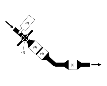
Figure 4 shows a schematic illustration of a device according to claim 6 for
carrying out
the described method. The exhaust gas generated by the diesel engine of the
most
modern type, the flow direction of which exhaust gas is denoted by the arrows,
comprises, in addition to the usual emissions of carbon monoxide, hydrocarbons
and
particles, nitrogen oxides with an NO2/NO x ratio of between 0.3 and 0.7.
Before the
exhaust gas passes the charging turbine (1), a reducing agent solution from a
reducing
agent reservoir (2) is supplied to said exhaust gas by means of a dosing
device. As a
reducing agent solution, use is preferably made of urea solution, or the
solution of
some other water-soluble compound which releases ammonia, which is supplied
from
a corresponding tank by means of a conventional injection device. Upon passing
the
charging turbine, in addition to the hydrolysis of the reducing agent
solution, a virtually
complete homogenization of reducing agent and exhaust gas takes place. An SCR
catalytic converter (3) is arranged at the outflow side of the charging
turbine in a
position close to the engine, which SCR catalytic converter (3) reduces the
nitrogen
oxides contained in the exhaust gas with the ammonia generated from the
hydrolysis of
the reducing agent solution, so as to form nitrogen. Only then are carbon
monoxide
(CO) and hydrocarbons (HC) made harmless, by means of oxidation to form carbon
dioxide (CO2), in an oxidation catalytic converter (4) which is arranged at
the outflow
side. Ammonia which is possibly still present in the exhaust gas, which
ammonia was
not consumed in the SCR catalytic converter, is likewise removed by oxidation
in the
oxidation catalytic converter. To keep temperature losses across the exhaust
system
as low as possible, and to thereby ensure the highest possible CO and HC
conversion
rates, the oxidation catalytic converter is preferably likewise arranged close
to the
engine, preferably in the same housing as the SCR catalytic converter (3). The
exhaust
gas which leaves said housing then contains only particles in addition to
harmless
constituents. Said exhaust gas flows onward to a diesel particle filter (5)
which, for
installation space reasons, is preferably arranged in the underbody region of
the
vehicle; as the exhaust gas passes through said diesel particle filter (5),
the particles
are filtered out, such that at the end of the system, exhaust gas which
satisfies the
legal requirements is discharged into the atmosphere.
To be able to operate the device according to the invention as effectively as
possible
and with high exhaust-gas purification efficiency, the selection of suitable
catalytic
CA 02729063 2010-12-22
WO 2009/156134 PCT/EP2009/004543
7
converters is also of some significance in addition to the correct practical
design.
The arrangement of the SCR catalytic converter close to the engine at the
inflow-side
end of the device therefore requires that the SCR catalytic converter which is
used
should have the highest possible resistance to contamination with regard to
hydrocarbons in addition to sufficient resistance to thermal aging at
temperatures of up
to 800 C. Not all conventional SCR catalytic converter technologies can meet
these
demands. Conventional zeolitic SCR catalytic converters, as are described for
example
in US 4,961,917, on account of their large zeolitic pore widths, have the
tendency to
accumulate hydrocarbons in the zeolitic framework, which leads to a blockage
of
ammonia storage locations and catalytic transition metal reaction centers
which are
essential for the functioning of said catalytic converters, and this can
considerably
reduce the activity of said catalytic converters. Conventional vanadium-
pentoxide-
based SCR catalytic converters usually do not have sufficient resistance to
thermal
aging.
In the device according to the invention, therefore, use is preferably made of
cerium-
oxide-based SCR technologies as are described for example in WO 2008/049491.
Particularly preferable are SCR catalytic converters based on transition-metal-
exchanged zeolite compounds or zeolite-like materials whose greatest lower
duct width
is between 2.6 and 4.2 angstrom (A), and whose greatest lower duct width
preferably
does not exceed a value of 4.0 0.1 A. SCR catalytic converters of said type
preferably contain zeolites or zeolite-like materials from the group
consisting of SAPO-
34, ferrierite, SAPO-11, chabazite, erionite and mixtures thereof, which has a
transition
metal content of 0.1 to 10% by weight in relation to the weight of the
zeolites or of the
zeolite-like material, wherein the transition metal is particularly preferably
selected from
iron, copper and mixtures thereof.
For the oxidation catalytic converter which is arranged at the outflow side of
the SCR
catalytic converter, the installation position, which is conventionally
characterized
primarily by a colder exhaust-gas temperature than in devices according to the
prior
art, requires that the catalytic converter should have an ignition temperature
(light-off
temperature) for the oxidation of hydrocarbons and carbon monoxide of a
maximum of
150 C. To meet said requirements, it is advantageous to use greater high-grade
metal
contents in the oxidation catalytic converter than in systems according to the
prior art.
Since, in the device according to the invention, the exhaust gas flowing
through the
CA 02729063 2010-12-22
WO 2009/156134 PCT/EP2009/004543
8
oxidation catalytic converter has already been denitrogenized, it is possible
to dispense
with good NO conversion rates. It is thereby possible for possible increased
costs,
which would initially be expected as a result of the high-grade metal quantity
which is to
be increased overall, to be compensated in that, instead of the otherwise
conventional
high proportions of platinum, greater quantities of the cheaper palladium are
used as a
catalytically active component. An oxidation catalytic converter which is used
in the
device according to the invention preferably comprises between 0.35 and 7
grams per
liter [g/L] of high-grade metal in relation to the catalytic converter volume,
particularly
preferably 3 to 5 g/L. The high-grade metal should be selected from the group
consisting of platinum, palladium, rhodium, iridium, ruthenium and mixtures
thereof.
Platinum is preferably used in combination with palladium, but for cost
reasons, not
rhodium. The platinum : palladium ratio should lie between 10:1 and 1:5,
preferably
between 8:1 and 1:1, particularly preferably between 5:1 and 2:1.
To ensure good light-off behavior of the oxidation catalytic converter, it is
advantageous if the oxidation catalytic converter is present in the form of a
catalytic
coating on a support body which warms up quickly. Such support bodies may for
example include metallic honeycomb bodies or ceramic thin-walled honeycomb
bodies
(wall thickness: 0.06 to 0.1 millimeters) with standard cell densities (62 to
124 cells per
square centimeter).
In the device according to the invention, as a diesel particle filter, use is
preferably
made of a catalytically coated wall-flow filter substrate composed of ceramic
material or
silicon carbide. The catalytic coating should be such that it firstly reduces
the soot
ignition temperature as effectively as possible, and secondly exhibits the
lowest
possible ignition temperature in the oxidation of hydrocarbons in order,
during the
active particle filter regeneration, to burn off unburned hydrocarbons, which
are
possibly present in the filter inlet, as quickly as possible and to thereby be
able to
contribute as effectively as possible to the generation of the exothermic
reaction
required for reaching the soot ignition temperature. For regular operation of
the diesel
particle filter between the active filter regeneration phases, it is also
advantageous if
the catalytic coating is such that hydrocarbons which possibly break through
the
oxidation catalytic converter, and nitrogen oxides which result from the over-
oxidation
of excess ammonia, can be converted with one another to form nitrogen, carbon
dioxide and water (so-called HC-deN0x properties). To obtain said
functionalities, the
catalytically active coating preferably comprises 0.15 to 2 grams per liter
[g/14 of high-
CA 02729063 2010-12-22
WO 2009/156134 PCT/EP2009/004543
9
grade metal selected from the group consisting of platinum, palladium and
mixtures
thereof, in relation to the volume of the diesel particle filter. 0.35 to 1
g/L of high-grade
metal is particularly preferable.
By way of example, a device according to the invention may be fitted with the
following:
= an SCR
catalytic converter, V = 3.0 L, comprising a honeycomb body with a cell
density of 62 cells per square centimeter and a cell wall thickness of 0.17
millimeters, which is provided with a catalytically active coating comprising
a
ferrierite-type zeolite which is exchanged with 5% by weight of copper and
which has a lower duct width of a maximum of 4.2 A;
= an oxidation catalytic converter, V = 2.0 L, comprising a ceramic honeycomb
body with a cell density of 62 cells per square centimeter and a cell wall
thickness of 0.1 millimeters, which is provided with a catalytically active
coating
which comprises 4 g/L of platinum and palladium, in the ratio 2:1, in relation
to
the volume of the oxidation catalytic converter, on a mixture of homogenous
silicon-dioxide/aluminum-dioxide mixed oxide and y aluminum oxide with an
active surface of 200 m2/g (BET); and
= a catalytically activated diesel particle filter with a volume of 4.0 L,
comprising a
ceramic wall-flow filter substrate with a cell density of 48 cells per square
centimeter and a porosity of 50%, in the walls of which is placed a
catalytically
active coating which has a high-grade metal content of 0.9 g/L, in relation to
the
volume of the diesel particle filter, and a platinum : palladium ratio of 1:1.
The device according to the invention is suitable for the purification of the
exhaust
gases of diesel vehicles, in particular for the purification of the exhaust
gases of diesel
passenger vehicles, in which engines with a turbocharger (charging turbine)
and an
exhaust-gas recirculation device are used.