Note: Descriptions are shown in the official language in which they were submitted.
CA 02729103 2010-12-22
WO 2010/006284 PCT/US2009/050288
MAGNETOSTRICTIVE AUDITORY SYSTEM
CROSS-REFERENCE TO RELATED APPLICATION
[0001] This application claims benefit of and priority to United States
Provisional Patent
Application serial number 61/080,180, entitled "Magnetostrictive Auditory
System" by Joan
M. Burleigh, et al., filed July 11, 2008, the entire content of which is
specifically
incorporated herein by reference for all that it discloses and teaches.
BACKGROUND OF THE INVENTION
[0002] Portable hearing devices have been very effective in assisting
individuals that have
impaired hearing and/or comprehension in difficult listening environments to
more clearly
hear, understand and enjoy auditory signals. Depending upon the type of
impairment that an
individual may have, or the environment in which the individual may have
difficulty hearing,
hearing devices may operate more efficiently with some individuals and not as
well with
others. Many of the problems associated with hearing loss as well as
comprehension of
audible signals are not well understood. A large number of factors can affect
both hearing
and comprehension of various types of audible signals. As a result, hearing
devices that aid a
user in hearing and comprehending audible signals may not be simply dependent
upon
amplification of the audible signal at specified frequencies.
SUMMARY OF THE INVENTION
[0003] An embodiment of the present invention may therefore comprise a method
of
assisting an individual with auditory comprehension of audible signals using a
hearing device
comprising: coating a conductive wire with a magnetostrictive coating; forming
the wire in a
coil; generating an electrical signal from the auditory signal; applying the
electrical signal to
CA 02729103 2010-12-22
WO 2010/006284 PCT/US2009/050288
the coil that causes the magnetostrictive coating to change size in response
to the electrical
signal so that the magnetostrictive coating generates auditory vibrations to
assist the
individuals with the auditory comprehension of audible sounds.
[00041 An embodiment of the present invention may therefore further comprise a
hearing
device that assists users having impaired auditory comprehension comprising: a
detector that
detects audible signals and translates the audible signals into an electrical
signal that varies in
amplitude in accordance with the audible signals; a driver that amplifies the
electrical signal
to provide an amplified electrical signal; a conductive wire formed in a coil
that is connected
to the driver to receive the amplified electrical signal and generate a
magnetic wave in
response to the electrical signal that varies in amplitude in accordance with
the amplitude of
the electrical signal; a first magnetostrictive coating substantially
surrounding the conductive
wire that changes size in response to the electrical signal and generates
auditory vibrations
corresponding to the amplitude of the electrical signal that assist the users
in comprehending
the audible signals.
[0005] An embodiment of the present invention may therefore further comprise a
method of
assisting an individual with auditory comprehension of audible signals using a
hearing device
comprising: forming a coil from a printed circuit board trace on a printed
circuit board;
covering the coil formed on the printed circuit board with a magnetostrictive
film; generating
an electrical signal from the auditory signal; applying the electrical signal
to the coil that
causes the magnetostrictive film to change size in response to the electrical
signal so that the
magnetostrictive film generates auditory vibrations to assist the individual
with the auditory
comprehension of audible signals.
[00061 An embodiment of the present invention may therefore further comprise a
hearing
device that assists users having impaired auditory comprehension comprising: a
microphone
that detects auditory signals and translates the auditory signals into an
electrical signal that
2
CA 02729103 2010-12-22
WO 2010/006284 PCT/US2009/050288
varies in amplitude in accordance with the auditory signals; a driver that
amplifies the
electrical signal to provide an amplified electrical signal; a coil formed
from a printed circuit
board trace on a printed circuit board; a first magnetostrictive film
substantially covering the
coil on the printed circuit board that changes size in response to a magnetic
field generated by
the amplified electrical signal that is applied to the coil and generates
auditory vibrations
corresponding to the amplitude of the amplified electrical signal that assist
the users in
comprehending the audible signals.
[0007] An embodiment of the present invention may therefore further comprise a
method of
assisting an individual with hearing an auditory signal using a hearing device
comprising:
coating a conductive wire with a magnetostrictive coating; forming the wire in
a coil;
generating an electrical signal from the auditory signal; applying the
electrical signal to the
coil that causes the magnetostrictive coating to change size in response to a
magnetic field
generated by the coil in response to the electrical signal so that the
magnetostrictive coating
generates auditory vibrations that assist the individual with hearing the
auditory signal.
[0008] An embodiment of the present invention may therefore further comprise a
hearing
device that assists users having impaired auditory function comprising: a
microphone that
detects auditory signals and translates the auditory signals into an
electrical signal that varies
in amplitude in accordance with the auditory signals; a driver that amplifies
the electrical
signal to provide an amplified electrical signal; a conductive wire formed in
a coil that is
connected to the driver to receive the amplified electrical signal and
generate a magnetic field
in response to the electrical signal that varies in amplitude in accordance
with the amplitude
of the electrical signal; a first magnetostrictive coating substantially
surrounding the
conductive wire that changes size in response to the magnetic field and
generates auditory
vibrations corresponding to the amplitude of the amplified electrical signal
that assist the
users in hearing the auditory signals.
3
CA 02729103 2010-12-22
WO 2010/006284 PCT/US2009/050288
[0009] An embodiment of the present invention may therefore further comprise a
method of
assisting an individual with hearing auditory signals using a hearing device
comprising:
forming a coil from a printed circuit board trace on a printed circuit board;
covering the coil
formed on the printed circuit board with a magnetostrictive film; generating
an electrical
signal from the auditory signal; applying the electrical signal to the coil
that causes the
magnetostrictive film to change size in response to the electrical signal so
that the
magnetostrictive film generates auditory vibrations to assist the individuals
with hearing the
auditory signals.
[0010] An embodiment of the present invention may therefore further comprise a
hearing
device that assists users having impaired hearing comprising: a detector that
detects auditory
signals and translates the auditory signals into an electrical signal that
varies in amplitude in
accordance with the auditory signals; a driver that amplifies the electrical
signal to provide an
amplified electrical signal; a coil formed from a printed circuit board trace
on a printed circuit
board; a magnetostrictive film substantially covering the coil on the printed
circuit board that
changes size in response to a magnetic field generated by the amplified
electrical signal that
is applied to the coil and generates auditory vibrations corresponding to the
amplitude of the
amplified electrical signal that assist the users in hearing the auditory
signals.
[0011] An embodiment of the present invention may therefore further comprise a
method of
assisting an individual with auditory comprehension and hearing of audible
signals using a
hearing device comprising: providing a diaphragm comprising a plastic and
magnetostrictive
material; forming a wire in a coil; mounting the diaphragm adjacent to the
coil; generating an
electrical signal from the auditory signal; applying the electrical signal to
the coil that causes
the magneto stri ctive material to change size in response to a magnetic field
generated by the
electrical signal applied to the coil so that the magnetostrictive material
generates auditory
vibrations to assist the individuals with the auditory comprehension of
audible sounds.
4
CA 02729103 2010-12-22
WO 2010/006284 PCT/US2009/050288
[0012] An embodiment of the present invention may therefore further comprise a
hearing
device that assists users having impaired auditory comprehension and hearing
comprising: a
detector that detects audible signals and translates the audible signals into
an electrical signal
that varies in amplitude in accordance with the audible signals; a driver that
amplifies the
electrical signal to provide an amplified electrical signal; a coil formed
from a conductive
wire that is connected to the driver to receive the amplified electrical
signal and generate a
magnetic field in response to the electrical signal that varies in amplitude
in accordance with
the amplitude of the electrical signal; a first diaphragm comprising a plastic
and
magnetostrictive material, the diaphragm mounted adjacent to the coil so that
magnetic flux
lines of the magnetic field cause the magnetostrictive material to change size
and generate
auditory vibrations in the diaphragm that correspond to the amplitude of the
electrical signal
that assist the users in comprehending and hearing the audible signals.
BRIEF DESCRIPTION OF THE DRAWINGS
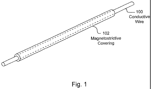
[0013] Figure 1 is a schematic illustration of one embodiment of a conductive
wire covered
with a magnetostrictive covering.
[0014] Figure 2 is a schematic illustration of another embodiment of a
conductive wire
covered with a magnetostrictive covering.
[0015] Figure 3 is a schematic illustration of a multi-coil winding that uses
conductive wires
having magnetostrictive covering.
[0016] Figure 4 is a schematic illustration of one embodiment of a printed
circuit board
device.
[0017] Figure 5 is a schematic illustration of an embodiment of a
magnetostrictive film.
[0018] Figure 6 is a schematic illustration of another embodiment of a
magnetostrictive film.
[0019] Figure 7 is a schematic illustration of another embodiment of a printed
circuit board
device.
CA 02729103 2010-12-22
WO 2010/006284 PCT/US2009/050288
[0020] Figure 8 is a schematic illustration of an embodiment of a hearing
device.
[0021] Figure 9 is a schematic illustration of another embodiment of a hearing
device.
[0022] Figure 10 is a perspective view of another embodiment.
[0023] Figure 11 is a side view of the embodiment of Figure 10.
[0024] Figure 12 is a cutaway view of another embodiment.
[0025] Figures 13-24 are graphs of test results.
DETAILED DESCRIPTION OF THE EMBODIMENTS
[0026] Figure 1 is a schematic illustration of a conductive wire 100 that is
covered by a
magnetostrictive covering 102. The magnetostrictive covering can comprise any
of the
magnetostrictive materials. For example, the magnetostrictive covering 102 may
be a
magneto stri ctive film, an amorphous metallic alloy, a metallic glass, a
metallic ribbon, a
glassy metal, a ribbon alloy, a shaped memory alloy, a metallic foil, a
metallic polymer or
other materials and shapes. In addition, metallic polymers can be extruded
over the
conductive wire 100 using standard extrusion techniques for placing covers
over wires to
form the magnetostrictive covering 102. Magnetostrictive materials convert
magnetic energy
into kinetic energy, or the reverse, and are typically used to build actuators
and sensors.
Magnetostrictive properties can be quantified by the magnetostrictive
coefficient (L), which
is the fractional change in length as the magnetization of the material
increases from zero to a
saturation value.
[0027] Cobalt exhibits the largest room temperature magnetostriction of a pure
element at 60
microstrain. Among alloys, the highest known magnetostriction is exhibited by
Terfenol-D.
Terfenol-D is represented as ThxDyl-xFe2. Terfenol-D exhibits approximately
2,000
microstrains in a field of 2 kOe (160 kA/m) at room temperature. Terfenol-D is
the most
widely used magnetostrictive material. As indicated above, it can be used as
an alloy or
6
CA 02729103 2010-12-22
WO 2010/006284 PCT/US2009/050288
mixed with polymers that can be extruded over the conductive wire 100.
Terfenol-D can also
be mixed with polymers to form a film, as disclosed in more detail below.
[0028] As shown in Figure 1, the magnetostrictive covering 102 has a certain
thickness. The
response of the magnetostrictive covering 102 is dependent, at least to some
extent, upon the
thickness of the magnetostrictive covering 102. In other words, the time
response and the
amount the magnetostrictive covering 102 change in size depend upon the
thickness of the
magnetostrictive covering 102.
[0029] Figure 2 illustrates another embodiment of a conductive wire that is
covered by a
magnetostrictive covering 202. As shown in Figure 2, the magnetostrictive
covering 202 is
thinner than the magnetostrictive covering 102 illustrated in Figure 1.
Magnetostrictive
covering 202 has a quicker response time than the magnetostrictive covering
102 of Figure 1
as a result of the fact that the magnetostrictive covering 202 is thinner. The
delayed response
of the magnetostrictive covering 102 is utilized in accordance with the
various embodiments
disclosed herein. Layering of 1 mm films can provide 8 mm film which can be
effectively
used on a diaphragm. Also, any desired thickness of the magnetostrictive
material, that is
mixed with a polymer, can be extruded directly on a diaphragm. Further, the
magnetostrictive material can be mixed with a polymer that is suitable to
function as a
diaphragm, so that the diaphragm can be extruded or molded with the
magnetostrictive
material disposed in the diaphragm.
[0030] Figure 3 is a schematic illustration of another embodiment. As shown in
Figure 3, a
multi-coil winding 300 is made from a wire 302 that is covered with a
magnetostrictive
covering or coating 304. The magnetostrictive covering 304 reacts to the
magnetic field that
is created by the current that passes through wire 302, which is applied to
the wire 302 by the
electronics package 306. Electronics package 306 can include any type of
electronics
including digital signal processors, microprocessors, active filters,
amplifiers, etc. The
7
CA 02729103 2010-12-22
WO 2010/006284 PCT/US2009/050288
magnetic field generated by the multi-coil winding 300 causes the
magnetostrictive covering
304 to change size. The multi-coil winding 300 with the magnetostrictive
coating 304 can be
used for hearing devices, as explained more fully below. The advantage of
using a
conductive wire, such as a copper wire, is that a copper wire, or similar
wire, such as a silver
wire, has very low resistance and is very efficient in generating a magnetic
field. Materials
that are magnetizable, such as ferrite based materials, have greater
resistance and are
therefore less efficient. Because of the small size of most hearing devices,
efficiency of the
system is important. Very small battery packs must be used in such small
devices, which
require higher efficiency. Hence, the highly conductive wire, such as a copper
wire or a
silver wire that is coated with a magnetostrictive material, has the advantage
of generating a
magnetic field very efficiently while allowing the magnetostrictive materials
to expand and
contract to efficiently generate the vibrations that enhance the auditory
comprehension of the
user.
[0031] Magnetostrictive materials, as indicated above, change shape and
produce mechanical
energy in response to a magnetic field. Conversely, the change in shape of the
magnetostrictive material stores energy so that when the magnetostrictive
material returns to
its original state, it generates a magnetic field that, in turn, will induce
current in the coil. In
this fashion, use of magnetostrictive material results in the efficient use of
energy and
minimal drainage of power from the battery. In that regard, changes in the
size of the
magnetostrictive material can be used to generate electricity and run various
types of devices
that use electrical energy. For example, the batteries in a hearing aid can be
charged using
this process.
[0032] The number of windings utilized in the multi-coil winding 300 that is
illustrated in
Figure 3 affects the magnitude of the magnetic field that is generated by the
multi-coil
winding 300. It is also believed that the spectral response of the auditory
vibrations of the
8
CA 02729103 2010-12-22
WO 2010/006284 PCT/US2009/050288
magnetostrictive coating 304 is affected by the number of windings. Hence, a
hearing device
can be empirically tuned to provide the desired spectral response by changing
the number of
windings in the coil.
[0033] Figure 4 is a schematic illustration of a coil 402 that is disposed on
a printed circuit
board 400. As shown in Figure 4, connectors 404, 406 are used to connect to
the spiral coil
402. The spiral coil 402 has a spiral shape, rather than a ring shape. In that
regard, the term
coil is used herein to include both helicoidal as well as ring coils.
Electrical connections can
be made to the connectors 404, 406 to drive a current through the spiral coil
402. The coil
402 and connectors 404, 406 are printed circuit board traces on the surface of
the printed
circuit board 400. The current that is applied to the coil 402 causes a
magnetic field to be
generated that is substantially perpendicular to the coil 402 at the surface
of the printed
circuit board 400. A magnetostrictive film 408 is placed over the coil 402.
The
magnetostrictive film may comprise a polymer film that includes a
magnetostrictive material
such as, but not limited to, Terfenol-D that is mixed with the polymer film.
The magnetic
field causes the magnetostrictive film 408 to change size in accordance with
the frequency of
the electrical signal.
[0034] Figure 5 is a schematic illustration of an embodiment of a
magnetostrictive film 500.
As shown in Figure 5, the magnetostrictive film 500 is thin. The
magnetostrictive film 500
that is illustrated in Figure 5 has a rapid response time in response to the
magnetic field that is
generated by the coil 402.
[0035] Figure 6 is an illustration of another embodiment of a magnetostrictive
film 600. As
shown in Figure 6, the magnetostrictive film 600 is a thicker film than the
magnetostrictive
film 500 of Figure 5. The magnetostrictive film 600 has a slower response time
than the
magnetostrictive film 500. In other words, there is a delay in the process of
causing the
magnetostrictive film 600 to change size in response to the magnetic field
generated by the
9
CA 02729103 2010-12-22
WO 2010/006284 PCT/US2009/050288
coil 402. A thicker coating on coils, traces or wires also may create a longer
delay. Hence, a
device, such as illustrated in Figure 4, that uses magnetostrictive film 600
would have a
longer response delay compared to a device, such as illustrated in Figure 4,
that uses the
thinner magnetostrictive film 500 of Figure 5.
[0036] Figure 7 is a schematic illustration of another embodiment that uses a
printed circuit
board 700 having a coil 704 formed from the printed circuit board leads. As
shown in Figure
7, a magnetostrictive film 706 covers the coil 704. The magnetostrictive film
706 may take
various shapes and have various thicknesses when deposited on the printed
circuit board. In
addition, various mixtures and concentrations of magnetostrictive materials
can be used. As
also shown in Figure 7, the electronic components 702 are disposed on an
opposite side of the
printed circuit board 700. The electronic component 702 can comprise various
types of
components including active filters, microprocessors, digital signal
processors, amplifiers,
and any other type of components used in hearing devices. A multi-layer
printed circuit
board may be used in this application to provide connections on an
intermediate layer.
Connectors 708, 710 provide connections to a battery pack or other power
supply. In this
fashion, an electronics package can be provided by the electronic components
706 that are
disposed on the printed circuit board 700. Alternatively, the coil 704,
magnetostrictive film
706 and the electronic components 702 can be mounted on the same side of the
board. In any
event, the electronic components 702 are mounted outside of the periphery of
the coil 704, so
as to minimize interference with the magnetic field that is generated by coil
704.
Alternatively, the magnetostrictive film 706, illustrated in Figure 7, may be
deposited on a
suspended diaphragm over the coil on the printed circuit board 700 to allow
greater
movement of the magnetostrictive film 706 and provide greater efficiency in
the production
of sound waves.
CA 02729103 2010-12-22
WO 2010/006284 PCT/US2009/050288
[0037] Figure 8 is a schematic illustration of a hearing device 800. The
hearing device 800
may comprise a hearing aid or hearing aid receiver, collectively referred to
as a hearing
device, that can be a miniaturized hearing aid that is disposed either
partially within, or fully
within, the ear canal of a user. The size of the components allows for
construction of the
hearing device 800 that can be inserted in the ear canal. In that regard, the
simplicity of the
construction of the embodiment of Figure 8 provides for a high degree of
miniaturization.
Further, the hearing device 800 of Figure 8 can also be disposed in other
types of hearing
devices, such as ear phones, telephones, speakers and other types of devices
that generate
auditory sound waves. As shown in Figure 8, the coil 802 has a
magnetostrictive coating,
such as illustrated in Figures 1 and 2. Alternatively, the coil 802 may be
wrapped with a
magnetostrictive film that comprises a magnetostrictive material, such as
Terfenol-D, that is
impregnated in a polymer or other film material. Coil 802 is connected to the
electronics
package 806 via connectors 804. Electronics package 806 receives an auditory
signal from
the microphone 812, which is amplified by the electronics package 806 and
applied via
connectors 804 to the coil 802. Battery 808 is connected to the electronics
package 806 via
connectors 810 to provide power to the hearing device 800. The
magnetostrictive material
efficiently changes shape in response to a magnetic field that is generated by
the current that
is running through the coil 802. The thickness of the magnetostrictive
coating, or the
thickness of the film applied around the coil 802, determines the response of
the
magnetostrictive material to the current that is applied to the coil 802. The
current that is
applied to the coil 802 generates a magnetic field that varies with the number
of coil windings
of the coil 802. The auditory vibrations of the coil 802 generate sound and
auditory
vibrational waves that assist the user in hearing, understanding and enjoying
auditory tones.
Sound waves and auditory vibrations are efficiently produced in the
magnetostrictive material
because of the close contact of the magnetostrictive material with the coil
802. In addition,
11
CA 02729103 2010-12-22
WO 2010/006284 PCT/US2009/050288
many harmonic frequencies are created because of the efficiency of the
magnetostrictive
coating in generating auditory vibrations. Again, this is due to the close
proximity of the
magnetostrictive coating to the wire of the coil 802. For hearing devices that
are inserted in
the ear canal, the auditory vibrations of the magnetostrictive coating on the
coil 802
additionally assist the user in hearing tonal frequencies. A significantly
improved hearing
response is achieved using the magnetostrictive coating on the coil. The
magnetostrictive
material tends to create some noise, which may assist the user in hearing, as
a result of the
stochastic resonance. Stochastic resonance may aid the user in the detection
and/or
enhancement of the auditory signal for easier hearing, identification and
enjoyment of the
auditory signal. In addition, Barkhausen noise may also assist the user in
hearing.
Barkhausen noise is the result of a series of sudden changes in the size and
orientation of
ferromagnetic domains, or microscopic clusters of aligned atomic magnets, that
occurs during
a continuous process of magnetization and demagnetization. In other words,
magnetization
and demagnetization occurs in minute steps. This creates a clicking or
crackling noise
because of the discontinuous jumps in magnetization. This may assist the user
in hearing, as
a result of stochastic resonance.
[0038] Although inner hair cells are outnumbered approximately four to one by
outer hair
cells, the inner hair cells gather and transmit the majority of auditory
information that reaches
the cerebral cortex. Because the cilia of the inner hair cells are not
attached to the tectorial
membrane, stimulation of the inner hair cells most likely results from motion
of the
surrounding fluid and basilar membrane. Brownian motion of the inner hair cell
bundles may
provide an optimal noise level that enhances the sensitivity of the
mechanical/electrical
transmission to weak acoustic signals. The vibrations provided by the coil
802, as well as the
strong magnetic field that is generated by the coil 802, may increase the
movement of the
fluid in the inner ear, which may increase the firing of the inner hair cells.
Therefore,
12
CA 02729103 2010-12-22
WO 2010/006284 PCT/US2009/050288
Brownian motion created by the embodiment illustrated in Figure 8 may serve to
provide a
greater opportunity for signal transmission in a user's ear that has
significant outer hair cell
damage and inner hair cells intact. In addition, the coil 802 with the
magnetostrictive coating
efficiently creates harmonics of the base frequencies that are very beneficial
to the
enhancement of speech discrimination.
[0039] As disclosed in Figures 1 and 2, magnetostrictive coatings can be used
that have
different thicknesses and different phase and time delay responses. The
constriction of two
different hearing devices 800 can be accomplished using two different
thicknesses of
magnetostrictive coverings. Different thicknesses can be provided using a
different number
of layers of magnetostrictive material. In this fashion, a hearing device
having the thicker
magnetostrictive covering 102 will have a delayed response and a different
phase.
[0040] Central auditory processing disorder (CAPD) is a condition in which the
user has
difficulty processing or interpreting auditory information in a less than
optimal listening
environment. Individuals with CAPD typically have normal hearing acuity, but
are unable to
efficiently process or interpret speech when placed in a minimally noisy
environment.
Children and adults with CAPD often report that they are confused or become
flustered in
busy, listening environments. In classroom environments, the workplace and
social
gatherings, these individuals often have difficulty and are confused by
different verbal
stimuli. CAPD may occur in persons with other disorders, such as autism,
ADD/ADHD,
sensatory integration dysfunction, learning disabilities, speech and language
deficients,
traumatic brain injury or other neurological conditions. CAPD may also appear
as an isolated
dysfunction. For children and adults with CAPD, there is evidence of binaural
asynchronies
(BAs) in their central auditory nervous system (CANS). Binaural asynchronies
are
synchrony disruptions (delay) in time of auditory input signals to the
individual's ears.
Efficient processing of acoustic information relies on binaural interaction or
synchronization
13
CA 02729103 2010-12-22
WO 2010/006284 PCT/US2009/050288
of auditory inputs between the two ears, which is accomplished by the central
auditory
nervous system in most individuals. For a person with a normal central
auditory nervous
system function, auditory input between the two ears is synchronized in time.
However, for
an individual with atypical central nervous system function, there are
asynchronies of various
magnitudes that hinder efficient auditory processing of acoustic information.
[00411 By introducing a delay in the auditory signals that are processed by
the hearing device
800 by using different thicknesses of magnetostrictive coverings, binaural
asynchronies can
be reduced or eliminated, and users can more effectively distinguish and
understand auditory
signals. This is a result of the fact that the magnetostrictive coverings 102,
202 can be used
to introduce a delay in one of the ears, which may assist the user in
synchronizing auditory
signals. Proper delay by using different thickness of magnetostrictive
materials can be
established empirically. The delay can also assist users having other
neurological disorders,
such as traumatic brain injury, Parkinson's disease, multiple sclerosis, etc.
[00421 Delay of the sound signal can also be assisted by employing the
concepts of the
invention in an ear canal device that has a duct that changes the propagation
length of the
sound for each individual ear. In other words, concepts of the various
embodiments may be
employed in the ear hearing device such that propagation lengths are different
for each ear.
Passive delay devices can be used separately or in conjunction with the
various embodiments
disclosed herein. Passive delay devices are more fully disclosed in U.S.
patent application
serial number 11/443,859, filed May 31, 2006, entitled "Apparatus and Methods
for
Mitigating Impairments Due to Central Auditory Nervous System Binaural Phase-
Time
Asynchrony," which is specifically incorporated herein by reference for all
that it discloses
and teaches.
[0043] Comprehension of auditory signals using hearing devices can be
negatively impacted
by electromagnetic interference. A multi-coil winding 300, such as shown in
Figure 3, that
14
CA 02729103 2010-12-22
WO 2010/006284 PCT/US2009/050288
has a magnetostrictive covering 102, or a magnetostrictive film 408 over a
coil 402, as shown
in Figure 4, is believed to reduce electromagnetic interference. For example,
appliances that
use a large amount of current, such as a computer monitor, television or other
similar device,
may create interference in a hearing device because of the electromagnetic
interference of the
electrical power signal applied to the appliance. Many hearing aids are
constructed using a
moving coil apparatus, or a balanced armature apparatus. Each of these devices
may function
as antennas that pick up the electromagnetic interference that is converted by
the hearing
device into an auditory hum that is transmitted to the user's ear. This may
also be the case
with electrostatic type of drivers that use electrically charged diaphragms.
The embodiments
disclosed herein are believed to reduce the electromagnetic interference and
provide a high
spectral response that aids users in hearing auditory signals. Use of
magnetostrictive
covering on loop systems that interact with a T coil system in a hearing aid
or other hearing
device, may result in less electromagnetic interference. Another possible
source of
interference that is encountered in standard hearing devices, and not
encountered in the
embodiments disclosed herein, is interference from magnetic fields. Many
standard hearing
devices operate by using a moving coil mechanism in which a moving coil is
attached to a
diaphragm that is exposed in a static magnetic field generated by a permanent
magnet.
Variations of the current that is applied to the coil causes the coil to
generate a magnetic field
that interacts with the static magnetic field and causes the coil to move on
the diaphragm. In
this fashion, sound waves are produced. Various electronic devices generate
magnetic fields
that perturb the static magnetic field of the permanent magnet in the hearing
device. These
perturbations in the static magnetic field create interference in the hearing
device. None of
the embodiments disclosed herein utilize a static magnetic field that can be
perturbed by
magnetic fields generated by various electronic devices. As a result,
interference by
magnetic field waves does not occur in the embodiments disclosed herein.
CA 02729103 2010-12-22
WO 2010/006284 PCT/US2009/050288
[0044] Figure 9 is a schematic illustration of another embodiment of a hearing
device 900.
Hearing device 900 is a device that is also amenable to miniaturization
because of its
compact size. As shown in Figure 9, a magnetostrictive film 902 is deposited
over coil 904.
Coil 904 is a coil that may be made from the printed circuit board traces of
printed circuit
board 906. Electronic components 908 may be disposed on the other side of the
printed
circuit board 906 from coil 904 or on the same side. Electronic components 908
may be
disposed around the periphery of the printed circuit board, or to one side of
the circuit board,
so that the magnetic waves generated by the coil 904 are not interrupted by
the electronic
components 908. The printed circuit board 906 and the electronic components
908 are
connected to a microphone 912 that detects auditory signals. These auditory
signals are
amplified and applied to the coil 904. Current in the coil 904 generates a
magnetic field that
causes the magnetostrictive film 902 to change size and generate auditory
vibrations. The
auditory vibrations of the magnetostrictive film 902 produce sound waves that
are efficiently
transmitted to the user. In addition, the auditory vibrations of the
magnetostrictive film 902
may be transmitted through the tissue in the user's ear to further assist in
hearing and
comprehension. Battery 910 supplies power to the electronic components 908 on
the printed
circuit board 906 via connectors 914.
[0045] The hearing device 900, illustrated in Figure 9, may be a hearing aid
that is disposed
in the outer ear, headphones, a telephone, a speaker or many other types of
hearing devices.
Since the magnetostrictive film 902 is placed directly over the coil 904, a
high degree of
efficiency is achieved in generating auditory vibrations. As a result,
multiple harmonic
frequencies are generated, which also assists the user in comprehending the
auditory signals
detected by the microphone 912. Of course, some auditory frequencies may be
amplified to a
greater extent than others, in accordance with the standard practice of
designing a hearing
device for a particular user. In general, however, the efficient operation and
generation of
16
CA 02729103 2010-12-22
WO 2010/006284 PCT/US2009/050288
multiple harmonic frequencies, as well as the generation of stochastic
resonances by both
hearing device 800 and hearing device 900, greatly increases the auditory
comprehension,
understanding and enjoyment by the user. Of course, the various embodiments
disclosed
herein can be disposed in any type of hearing device including headphones,
speakers, ear
pods, etc. and could be used by individuals who do not have hearing loss and
do not have
hearing comprehension problems, but, rather, like to enjoy an audio response
and take full
advantage of the attributes of various embodiments disclosed herein. Further,
each of the
devices disclosed herein can be encapsulated in a standard package for
connection to a device
such as a headphone, speaker, etc. In that regard, the encapsulated packages
can be sold as
modular devices that can be employed in any desired fashion, such as any type
of hearing
device, including hearing aids, headphones, speakers, etc.
[0046] Figures 10 and 11 disclose a magnetostrictive diaphragm design for
hearing devices.
Figure 10 is a perspective view of the magnetostrictive diaphragm design 1000,
while Figure
11 is a side view. As shown in Figure 10, coil 1002 is attached to lead wires
1004, 1006 that
apply electrical signals to the coil 1002 that are representative of auditory
signals. The coil
1002 may comprise a conductive wire such as conductive wire 200 that is
surrounded by
magnetostrictive covering 2002. Alternatively, coil 1002 may be wrapped in a
magnetostrictive film or over-molded with a magnetostrictive plastic over-
molding. Further,
coil 1002 may contain no magnetostrictive materials. Coil 1002 is placed
adjacent a ring
1012, as disclosed in both Figures 10 and 11. Ring 1012 is a support ring that
supports a
magnetostrictive diaphragm 1008 that is suspended from the ring by a flexible
membrane
1014. Magnetostrictive diaphragm 1008 can be formed from a thin polymer or
plastic
material that is embedded or mixed with magnetostrictive materials. Cone 1010
is an
optional feature that can be used to direct the audio signals that are
generated by the
magnetostrictive diaphragm 1002.
17
CA 02729103 2010-12-22
WO 2010/006284 PCT/US2009/050288
[0047] In operation, the coil 1002 of Figures 10 and 11 generates a magnetic
field that varies
with the application of the electrical signal that is applied to lead wires
1004, 1006. The
magnetic field penetrates the coil and the magnetostrictive diaphragm 1008 as
shown by the
exemplary magnetic flux line 1018. As the magnetic field generated by the coil
1008 varies
in response to the electrical signal applied to lead wires 1002, 1006, the
magnetostrictive
materials change size which causes diaphragm 1008 to move and push the
surrounding air to
create sound waves. In other words, the magnetostrictive diaphragm 1008
includes
magnetostrictive materials that change size in the magnetic field created by
the coil 1002 and
cause the magnetostrictive diaphragm 1008 to move response to the magnetic
field. In
addition, Ferrofluid, which is produced by Ferrotec Corporation, can also be
coated on the
magnetostrictive diaphragm 1008 to further assist in driving the
magnetostrictive diaphragm
1008. Ferrofluid is available from Ferrotec Corporation located in Bedford,
New Hampshire,
and San Jose, California.
[0048] Figure 12 is a cutaway view of an embodiment of a headphone unit 1200.
As shown
in Figure 12, the headphone unit 1200 includes a speaker 1202, a headphone
coil 1204 and a
headphone magnet 1206. These are the standard components that are found in
typical
headphones. As also shown in Figure 12, a multicoil winding 1210 is embedded
in a mylar
covering 1208 and placed over the rear portion of the headphone unit adjacent
the headphone
magnet 1206 and the headphone coil 1204. The mylar covering 1208 can be
friction fit to the
back of the headphone unit or can be attached by other mechanical means, such
as by
adhesives, etc. A plurality of layers of magnetostrictive film 1212 are then
placed over the
mylar covering 1208 and the multicoil winding 1210. The magnetostrictive film
may
comprise a polymer that is mixed with particles of magnetostrictive material.
In one
embodiment, each layer of magnetostrictive film has a thickness of 1 mil. The
headphone
wire 1216 that is attached to the headphone coil 1204 can be clipped and
attached to multicoil
18
CA 02729103 2010-12-22
WO 2010/006284 PCT/US2009/050288
winding wire 1218. Multicoil winding wire 1220, which is at the other end of
the multicoil
winding 1210, can then be connected to the drive source for the headphone unit
1200. The
headphone wire 1214, which is at the other end of the headphone coil 1204, can
remain
attached to the driving source. In this manner, multicoil winding 1210 is
placed in series with
the headphone coil 1204.
[0049] The headphone unit 1200 that is illustrated in Figure 12 provides
excellent speech
discrimination for both hearing impaired users and users with no hearing loss.
Tests on
similar headphones are described below, which show increased speech
discrimination using
similarly modified headphone units. Of course, any type of auditory speaker
system can be
modified in this manner, including headphones that are used in telephones, ear
pods, hearing
aids, speakers and similar devices. The multiple layers of magnetostrictive
film 1212 also
assist in blocking electromagnetic interference, which may be generated by
noisy appliances,
computers, cell phones, etc.
[0050] Tests were performed using headphones that have been modified by
placing a
magnetostrictive polymer film over the headphone coil similar to the
embodiment of Figure
12. Groove headphones, model TM-707v, available from Groove Industries Co.
Ltd, Rm703
A, Huangdu Plaza Yitian Rd, Futian, Shenzhen, China, were modified to
determine speech
discrimination. The ear assembly cover of the headphone was pried open to
expose the
speaker assembly. A circle of thin black foam padding was removed and eight
pieces of 1
MIL amorphous magnetostrictive film, that were cut into 11/16 " squares, were
stacked
together and enclosed with electrical tape. The stacked pieces were then tapes
to the speaker
assembly of the headphone with a metal assembly placed on top of the tape
strip. A 100 turn,
36G wire coil assembly was then placed on top of the metal layers. The red
wire from the
speaker was then removed and one end of the coil was attached to the speaker
where the red
wire was removed. The other coil wire was then attached to the red wire that
was removed
19
CA 02729103 2010-12-22
WO 2010/006284 PCT/US2009/050288
from the speaker. The earpiece assembly was then reassembled and the other
earpiece was
modified in the same manner.
[0051] Subjects were tested to determine potential benefit from the
retrofitted headphones.
Speech discrimination measurements were made with both the modified headphones
and
unmodified headphones in both quiet and noisy environments. One of the most
challenging
areas for audio and assistive devices for those with hearing loss involves the
enhancement of
speech understanding in the presence of noise. Understanding speech in noise
continues to
be the most prevalent complaint of individuals using hearing aids. Designing
affordable and
easily embedded technology in various audio systems, such as headphones,
telephones and
hearing aids to address enhancement of speech understanding in noisy
environments provides
great assistance to many individuals.
[0052] The subjects in the testing of the modified headphones were 75 native
English
speaking male and female subjects from eight years to adult. Participants were
recruited
from Northern Colorado. The 75 participants were broken into the following
groups: 1)
normal hearing; 2) hearing loss; 3) central auditory processing disorder. All
participants were
separated into these groups based upon their pure tone findings and, for those
included in the
central auditory processing disorder group, by simple auditory processing
testing.
Participants with hearing loss had hearing thresholds span levels of
impairment from a mild
degree through profound. Various types of hearing loss and configurations of
impairment
were included in the study.
[0053] The participants were evaluated using strict audiologic controls. All
audiologic
testing procedures were conducted in a double walled, IAC, soundproof room. A
Grason-
Stadler (GSI-61) diagnostic audiometer was used to present test items to
participants via
TDH-50 electrodynamic earphones (10 ohm, mounted in MX/41 AR cushions). The
audiometer was calibrated in accordance with ANSI (1989 S3.6) specifications
before the
CA 02729103 2010-12-22
WO 2010/006284 PCT/US2009/050288
collection of data. Speech stimuli for monosyllabic word testing was played on
a CD player
and passed through the speech circuit of the GSI-61 diagnostic audiometer.
Speech reception
thresholds (SRT) were established using the W-1 CID Spondee word list, and
speech
discrimination scores in quiet were obtained using Campbell's word lists.
Campbell's word
lists are standardized and are commonly used in auditory studies. The pattern
of each
monosyllabic word was of the consonant-vowel-consonant type. Impedance
audiometry was
also performed using the Grason-Stadler, Model TympStar impedance unit.
Tympanometry
was administered for both ears. Three targeted headphones (TH-50 Groove, Model
707 non-
retrofitted headphone, Groove, Model 707 retrofitted headphone) were
introduced during the
final phase of testing. These included standard diagnostic TDH-50 headphones,
Groove,
Model 707, headphones and Groove, Model 707, retrofitted headphones with new
hearing
technology. All headphones were calibrated according to ISO (1964) and ANSI
(1969)
standards. Correction factors were employed throughout testing for each
headphone to
maintain consistency in output for all headphones and test stimuli. NU-6
phonetically
balances word list (Tillman & Carhart 1966) (Lists Al, A2, A4, B1, B2 and B4)
were used to
determine single words speech discrimination scores in noise. These words were
presented
via a CD player using a CD recorded by Auditec of St. Louis. Words were
presented through
the targeted headphones via the Grason-Stadler, Model GSI-61, diagnostic
audiometer.
These words were presented at 40 dB SL re pure tone average with signal-to-
noise ratio of +6
using speech band noise presented ipsilaterally. These word lists are
standardized and are
commonly used in auditory studies. The pattern of each monosyllabic word was
of the
consonant-vowel-consonant type. Results of this testing are shown in Figures
13 and 14.
[0054] Figure 13 discloses a graph 1300 of the mean speech discrimination
scores in noise
for individuals with hearing loss using three different headphones. As shown
in Figure 13,
the retrofitted headphones provided much better speech discrimination.
21
CA 02729103 2010-12-22
WO 2010/006284 PCT/US2009/050288
[0055] Figure 14 is a graph 1400 of the mean speech discrimination scores in
noise for
individuals with normal hearing using three different headphones. As shown in
Figure 14,
the retrofitted headphones provided much greater speech discrimination for
users with normal
hearing.
[0056] Figures 15-24 are graphs of additional test results on the HPA-1000C
non-retrofitted
headphone and the HPA-1016C retrofitted headphone. Figures 15 and 16 show
impedance
measurements of the headphones versus frequency. Figure 15 is a graph 1500 of
the
impedance of an HPA-1000C headphone that is not retrofitted. Figure 16 is a
graph 1600 of
the impedance of an HPA-1016C headphone with the retrofitted technology. The
impedance
measurements are of interest since these graphs show how much of a load each
headphone
places on the circuit driving the headphone. The lower the impedance of the
headphone, the
greater the load on the driving circuit. Figure 17 is a graph 1700 that shows
the second and
fourth even order harmonic distortion of the HPA-1000C headphones that have
not been
retrofitted using a 63 mV drive. Figure 18 is a graph 1800 that shows the
third and fifth odd
order harmonic distortions of the HPA-1000C non-retrofitted headphones using a
63 mV
drive. Figure 19 is a graph 1900 that shows the second and fourth even order
distortion of the
HPA-1016C retrofitted headphones, using a 63 mV drive. As shown in Figure 19,
the
harmonic distortion of the even orders is much greater for the retrofitted
headphones than the
even order distortion illustrated in Figure 17. Figure 20 is a graph 2000 that
shows the third
and fifth odd order harmonic distortion of the HPA-1016C retrofitted
headphones using a 63
mV drive. Figure 20 shows much larger harmonic distortions for the retrofitted
headphones
than the non-retrofitted headphones, for the third and fifth odd order
harmonics, illustrated in
Figure 18. Figure 21 is a graph 2100 of the total harmonic distortion of the
HPA-1000C non-
retrofitted headphones using a 63 mV drive. Figure 22 is a graph 2200 of the
total harmonic
distortion plus noise of the HPA-1000C non-retrofitted headphones using a 63
mV drive.
22
CA 02729103 2010-12-22
WO 2010/006284 PCT/US2009/050288
Figure 23 is a graph 2300 of the total harmonic distortion of the HPA-1016C
retrofitted
headphones using a 63 mV drive. As shown in Figure 23, there is substantially
greater total
harmonic distortion of the retrofitted headphones than that illustrated in
Figure 21, especially
at lower frequencies. Figure 24 is a graph 2400 of the total harmonic
distortion plus noise of
the HPA-1016C retrofitted headphones using a 63 mV drive. Again, there is a
substantially
larger amount of total harmonic distortion illustrated in Figure 24, as
compared to that shown
in Figure 22, especially at lower frequencies. Hence, these tests illustrate
that harmonic
distortion is increased with the modified headphones which may assist in the
process of
speech discrimination. All of the measurements were made with a gold-Line TEF
25
analyzer. Level calibration was performed by a Bruel & Kjaer 4231 calibrator.
Acoustic
measurement was performed by a General Radio (GenRad) 1560-T83 earphone
coupler with
a 1987-2050 adapter. The microphone used was a Sound First SFl 11 Type 1
microphone.
The headphones were driven by a Whirlwind PA-1 headphone amplifier set for
unity gain.
The headphone amplifier has an output impedance of 10 ohms.
[0057] The foregoing description of the invention has been presented for
purposes of
illustration and description. It is not intended to be exhaustive or to limit
the invention to the
precise form disclosed, and other modifications and variations may be possible
in light of the
above teachings. The embodiment was chosen and described in order to best
explain the
principles of the invention and its practical application to thereby enable
others skilled in the
art to best utilize the invention in various embodiments and various
modifications as are
suited to the particular use contemplated. It is intended that the appended
claims be
construed to include other alternative embodiments of the invention except
insofar as limited
by the prior art.
23