Note: Descriptions are shown in the official language in which they were submitted.
CA 02729293 2010-12-23
WO 2010/036608 PCT/US2009/057668
ARRANGEMENT FOR AND METHOD OF
CONTROLLING IMAGE CAPTURE PARAMETERS
IN RESPONSE TO MOTION OF AN IMAGING READER
DESCRIPTION OF THE RELATED ART
[0001] Solid-state imaging systems or imaging readers, as well as moving
laser beam readers or laser scanners, have both been used to electro-optically
read
targets, such as one-dimensional bar code symbols, particularly of the
Universal
Product Code (UPC) type, each having a row of bars and spaces spaced apart
along
one direction, as well as two-dimensional symbols, such as Code 49, which
introduced the concept of vertically stacking a plurality of rows of bar and
space
patterns in a single symbol. The structure of Code 49 is described in U.S.
Patent No.
4,794,239. Another two-dimensional code structure for increasing the amount of
data
that can be represented or stored on a given amount of surface area is known
as
PDF417 and is described in U.S. Patent No. 5,304,786.
[0002] The imaging reader includes an imaging module having a solid-state
imager with a sensor array of cells or photosensors, which correspond to image
elements or pixels in a field of view of the imager, and an imaging lens
assembly for
capturing return light scattered and/or reflected from the symbol being
imaged, and
for projecting the return light onto the sensor array to initiate capture of
an image of
the symbol. Such an imager may include a one- or two-dimensional charge
coupled
device (CCD) or a complementary metal oxide semiconductor (CMOS) device and
associated circuits for producing and processing electronic signals
corresponding to a
one- or two-dimensional array of pixel information over the field of view. The
imager captures the return light over an exposure time period under the
control of a
-1-
CA 02729293 2010-12-23
WO 2010/036608 PCT/US2009/057668
controller that is also operative for processing the electrical signals into
data
indicative of the symbol being imaged and read.
[0003] It is therefore known to use the imager for capturing a monochrome
image of the symbol as, for example, disclosed in U.S. Patent No. 5,703,349.
It is
also known to use the imager with multiple buried channels for capturing a
full color
image of the symbol as, for example, disclosed in U.S. Patent No. 4,613,895.
It is
common to provide a two-dimensional CCD with a 640 x 480 resolution commonly
found in VGA monitors, although other resolution sizes are possible.
[0004] In order to increase the amount of the return light captured by the
imager, especially in dimly lit environments and/or at far range reading, the
imaging
reader generally also includes an illuminating light assembly, also under
control of the
controller, for illuminating the symbol with illumination light for reflection
and
scattering therefrom. The illumination is preferably pulsed for an
illumination time
period that is in synchronism with the exposure time period, but can also be
continuous.
[0005] Yet, the use of an imaging reader, especially a handheld movable
reader, for reading symbols located anywhere within a range of working
distances
relative to the reader has proven to be challenging. An operator cannot see
exactly
whether a symbol is within the field of view of the array during reading for
optimum
reading within the working range. It is not uncommon for the operator to
repeatedly
move the portable reader in multiple side-to-side, up-and-down, and back-and-
forth,
directions and repeatedly aim the portable reader at a single symbol several
times
before an indicator advises the operator that the symbol has been successfully
imaged
and read, thereby slowing down transaction processing and reducing
productivity.
-2-
CA 02729293 2010-12-23
WO 2010/036608 PCT/US2009/057668
[0006] Such operator movement, including the ever present shake or jitter
imparted to the portable reader by the operator's hand, especially pronounced
when
the handheld reader is small and light in weight, blurs the captured image and
can
prevent the symbol from being successfully read. The longer the exposure time
period, the greater the degree of image blur will be present. To minimize the
degree
of image blur, the reader can be preset with fixed image capture parameter
values set
in advance to try and reduce the effects of such motion in most situations.
Thus, the
exposure time period and/or the illumination time period can each be preset to
fixed
short times and/or the illumination can be set to a fixed, very bright
intensity level.
[0007] As advantageous as such preset parameter values are in attempting to
capture a blur-free image, they are not optimal or suitable for all operators,
or for all
applications. Compromises inevitably occur in the amount of noise and blur
that can
be tolerated in the image, as well as in the brightness and the depth of field
of the
image. Excessive hand jitter or hand motion by a particular operator cannot be
taken
into account in advance and can often result in noisy, blurred, dark images of
short
depth of field, which degrade reading performance of symbols, especially those
of
high density and located far from the reader.
SUMMARY OF THE INVENTION
[0008] One feature of the present invention resides, briefly stated, in an
arrangement for reducing image blur in response to motion of an imaging reader
for
imaging symbols to be read. The arrangement includes an illuminating light
assembly
supported by the reader for illuminating a symbol with illumination light
having an
intensity level over an illumination time period. Preferably, the illuminating
light
-3-
CA 02729293 2010-12-23
WO 2010/036608 PCT/US2009/057668
assembly includes a light emitting diode (LED) for emitting the illumination
light as a
light pulse.
[0009] The arrangement further includes a solid-state imager supported by the
reader and having an array of image sensors for capturing return light from
the
symbol over a field of view over an exposure time period. Preferably, the
imager is a
CCD or a CMOS with a rolling or a global shutter. The array may be one-
dimensional, i.e., linear arranged along a single row, or two-dimensional
having
mutually orthogonal multiple rows and columns.
[0010] The arrangement yet further includes a motion sensor supported by the
reader for detecting the motion of the reader, and for generating a motion
signal in
response to the detected motion of the reader. Preferably, the motion sensor
is an
accelerometer, a gyroscope, or an analogous mechanical motion detector, and
the
motion signal has an amplitude proportional to a magnitude and a direction of
the
detected motion of the reader.
[0011] The arrangement also includes a controller operatively connected to
the motion sensor, for dynamically controlling at least one of the time
periods and the
intensity level in real time in response to the motion signal to optimally
image the
symbol. Preferably, the controller is operative for dynamically decreasing the
at least
one of the time periods and simultaneously increasing the intensity level of
the
illumination light. Still another image capture parameter that could be
controlled by
the controller is the gain of the imager.
[0012] Thus, in accordance with this invention, image capture parameter
values are not preset, but are dynamically adjusted in real time. A high
amount of
noise and blur is no longer accepted or tolerated in the image. The brightness
and the
-4-
CA 02729293 2010-12-23
WO 2010/036608 PCT/US2009/057668
depth of field of the image is adjusted to be optimal for the particular
application.
Excessive hand jitter or hand motion by a particular operator is affirmatively
taken
into account by the motion sensor. Reading performance of symbols, especially
those
of high density and located far from the reader, is enhanced.
[0013] The method of reducing image blur, in response to motion of an
imaging reader for imaging symbols to be read, is performed by illuminating a
symbol
with illumination light having an intensity level over an illumination time
period,
capturing return light from the symbol over a field of view of a solid-state
imager
over an exposure time period, detecting the motion of the reader with a motion
sensor
supported by the reader, generating a motion signal in response to the
detected motion
of the reader, and dynamically controlling at least one of the time periods
and the
intensity level in real time in response to the motion signal to optimally
image the
symbol.
[0014] The novel features which are considered as characteristic of the
invention are set forth in particular in the appended claims. The invention
itself,
however, both as to its construction and its method of operation, together
with
additional objects and advantages thereof, will be best understood from the
following
description of specific embodiments when read in connection with the
accompanying
drawings.
BRIEF DESCRIPTION OF THE DRAWINGS
[0015] FIG. 1 is a perspective view of a portable imaging reader operative in
either a handheld mode, or a hands-free mode, for capturing return light from
target
symbols; and
-5-
CA 02729293 2010-12-23
WO 2010/036608 PCT/US2009/057668
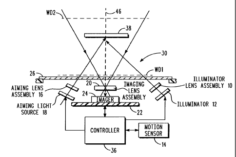
[0016] FIG. 2 is a schematic diagram of various components of the reader of
FIG. 1 in accordance with this invention.
DETAILED DESCRIPTION OF THE PREFERRED EMBODIMENTS
[0017] Reference numeral 30 in FIG. 1 generally identifies an imaging reader
having a generally vertical window 26 and a gun-shaped housing 28 supported by
a
base 32 for supporting the imaging reader 30 on a countertop. The imaging
reader 30
can thus be used in a hands-free mode as a stationary workstation in which
products
are slid, swiped past, or presented to, the vertical window 26, or can be
picked up off
the countertop and held in an operator's hand and used in a handheld mode in
which
the reader is moved and a trigger 34 is manually depressed to initiate imaging
of
indicia, especially one- or two-dimensional symbols, to be read at far
distances from
the window 26. In another variation, the base 32 can be omitted, and housings
of
other configurations can be employed. A cable, as illustrated in FIG. 1,
connected to
the base 32 can also be omitted, in which case, the reader 30 communicates
with a
remote host by a wireless link, and the reader is electrically powered by an
on-board
battery.
[0018] As schematically shown in FIG. 2, an imager 24 is mounted on a
printed circuit board 22 in the reader. The imager 24 is a solid-state device,
for
example, a CCD or a CMOS imager having a one-dimensional array of addressable
image sensors or pixels arranged in a single, linear row, or a two-dimensional
array of
such sensors arranged in mutually orthogonal rows and columns, and operative
for
detecting return light captured by an imaging lens assembly 20 along an
optical path
or axis 46 through the window 26. The return light is scattered and/or
reflected from
-6-
CA 02729293 2010-12-23
WO 2010/036608 PCT/US2009/057668
a target or symbol 38 over the field of view. The imager 24 captures the
return light
over an exposure time period. The imaging lens assembly 20 is operative for
adjustably focusing the return light onto the array of image sensors to enable
the
symbol 38 to be read. The symbol 38 is located anywhere in a working range of
distances between a close-in working distance (WD1) and a far-out working
distance
(WD2). In a preferred embodiment, WD1 is about four to six inches from the
imager
array 24, and WD2 can be many feet from the window 26, for example, around
fifty
feet away.
[0019] An illuminating assembly is also mounted in the imaging reader and
preferably includes an illuminator or illuminating light source 12, e.g., a
light emitting
diode (LED), and an illuminating lens assembly 10 to uniformly illuminate the
symbol 38 with an illuminating light having an intensity level over an
illumination
time period. The LED 12 is preferably pulsed.
[0020] An aiming assembly is also mounted in the imaging reader and
preferably includes an aiming light source 18, e.g., an LED, and an aiming
lens
assembly 16 for generating a visible aiming light pattern on the symbol 38.
The
aiming pattern is useful to help the operator accurately aim the reader at the
symbol
38.
[0021] As shown in FIG. 2, the imager 24, the illuminating light source 12 and
the aiming light source 18 are operatively connected to a controller or
microprocessor
36 operative for controlling the operation of these components, especially one
or more
of the image capture parameters, such as the intensity level of the
illuminating light,
the duration of the illumination time period, the duration of the exposure
time period,
and the gain of the imager 24. Preferably, the microprocessor is the same as
the one
-7-
CA 02729293 2010-12-23
WO 2010/036608 PCT/US2009/057668
used for processing the return light from target symbols and for decoding the
captured
target images.
[0022] As also shown in FIG. 2, a motion sensor 14 is operatively connected
to the controller 36. The motion sensor 14 is positioned and supported within
the
reader. The motion sensor 14 may be a gyroscope, an accelerometer, or some
other
mechanical device that provides an electrical output motion signal
proportional to a
magnitude and a direction of motion of the reader. As described above, the
reader is
moved by the operator to aim the reader at the symbol. Also, unavoidable hand
jitter
of the reader often occurs during image capture. The output motion signal of
the
motion sensor 14 is conducted to the controller 36, which then dynamically
adjusts
the image capture parameters in real time. If the motion and the magnitude of
the
motion signal are high, then the controller 36 calculates that the
illumination and
exposure time period is proportionately low, that the intensity level of the
illumination
light is correspondingly high, and that the gain of the imager is
correspondingly low.
Conversely, if the motion and the magnitude of the motion signal are low, then
the
controller 36 calculates that the illumination and exposure time period is
proportionately high, that the intensity level of the illumination light is
correspondingly low, and that the gain of the imager is correspondingly high.
[0023] In operation, the controller 36 sends a command signal to energize the
aiming light source 18 prior to reading, and also pulses the illuminating
light source
12 for the calculated illumination time period, say 500 microseconds or less,
and at
the calculated intensity level, and energizes and exposes the imager 24 to
collect light,
e.g., illumination light and/or ambient light, from the symbol only during the
calculated exposure time period and with a calculated gain. A typical array
needs
-8-
CA 02729293 2010-12-23
WO 2010/036608 PCT/US2009/057668
about 33 milliseconds to acquire the entire target image and operates at a
frame rate of
about 30 frames per second.
[0024] Limiting the exposure time period also minimizes the amount of the
captured return light. As a result, the captured image will often appear dark.
Yet, for
reading bar code symbols, darker images are often easier to decode than
blurred ones.
Hence, this invention has particular utility for reading bar code symbols.
[0025] It will be understood that each of the elements described above, or two
or more together, also may find a useful application in other types of
constructions
differing from the types described above. For example, the illumination light
source
12 need not be an LED, but could be a laser, a strobe, a xenon flash lamp, or
another
type of light source. Also, there need not be a single source, but a plurality
of sources
is contemplated, in which case, any of the number, intensity, duration and
timing of
one or more of the sources could be controlled by the controller 36.
[0026] While the invention has been illustrated and described as an
arrangement for, and a method of, controlling image capture parameters in
response to
motion of an imaging reader, it is not intended to be limited to the details
shown,
since various modifications and structural changes may be made without
departing in
any way from the spirit of the present invention. For example, rather than
hardwiring
the motion sensor 14 to the controller, a software solution might be
implemented.
Also, this invention is not to be limited solely to imaging readers whose only
function
is to image bar code symbols, but could equally apply to mobile computers or
terminals having an imager as one of its subsystems.
[0027] Without further analysis, the foregoing will so fully reveal the gist
of
the present invention that others can, by applying current knowledge, readily
adapt it
-9-
CA 02729293 2010-12-23
WO 2010/036608 PCT/US2009/057668
for various applications without omitting features that, from the standpoint
of prior
art, fairly constitute essential characteristics of the generic or specific
aspects of this
invention and, therefore, such adaptations should and are intended to be
comprehended within the meaning and range of equivalence of the following
claims.
[0028] What is claimed as new and desired to be protected by Letters Patent is
set forth in the appended claims.
-10-