Note: Descriptions are shown in the official language in which they were submitted.
HIP AND RIDGE ROOFING SHINGLE
BACKGROUND
[0001] Asphalt-based roofing materials, such as roofing shingles, roll
roofing and
commercial roofing, are installed on the roofs of buildings to provide
protection from the
elements. The roofing material may be constructed of a substrate such as a
glass fiber mat or
an organic felt, an asphalt coating on the substrate, and a surface layer of
granules embedded
in the asphalt coating.
[0002] Roofing materials can be applied to roofs having various surfaces
formed by
roofing planes. The various surfaces and roofing planes form intersections,
such as for
example, hips and ridges. A ridge is the uppermost horizontal intersection of
two sloping roof
planes. Hips are formed by the intersection of two sloping roof planes running
from a ridge to
the eaves.
[0003] It would be desirable to improve the methods used to manufacture hip
and ridge
roofing material to be more efficient.
SUMMARY
[0004] In accordance with one embodiment there is provided a shingle blank
comprising:
an underlay portion having a substrate coated with an asphalt coating and
granules, the
underlay portion having an upper edge and a lower edge; a separate overlay
portion adhered
to the underlay portion, the overlay portion comprising a substrate coated
with an asphalt
coating and granules and having more than one layered segment, at least one of
the layered
segments being folded over on top of at least one of the other layered
segments, each of the
layered segments connected together by a common substrate, the layered
segments having a
sealant bead forming an adhesive seal therebetween, wherein the entirety of
the overlay
portion is disposed on an upper surface of the underlay portion; and a
plurality of perforation
lines extending in a perpendicular direction from an upper edge of the overlay
portion to the
lower edge of the underlay portion; wherein the plurality of perforation lines
are configured to
facilitate separation of the shingle blank to form hip and ridge roofing
shingles configured for
application across a ridge or hip.
1
CA 2729373 2017-06-19
[0005] In accordance with another embodiment there is provided a method of
installing a
hip and ridge roofing shingle, comprising the steps of: providing an asphalt-
based shingle
blank having an overlay portion adhered to an underlay portion, the underlay
portion having a
substrate coated with an asphalt coating and granules, the underlay portion
having an upper
edge and a lower edge, the overlay portion comprising a substrate coated with
an asphalt
coating and granules and having more than one layered segment, at least one of
the layered
segments being folded over on top of at least one of the other layered
segments, each of the
layered segments connected together by a common substrate, the layered
segments having a
sealant bead forming an adhesive seal therebetween, wherein the entirety of
the overlay
portion is disposed on an upper surface of the underlay portion, wherein a
plurality of
perforation lines extend in a perpendicular direction from an upper edge of
the overlay portion
to the lower edge of the underlay portion; separating the shingle blank along
the plurality of
perforation lines to form hip and ridge roofing shingles; and installing the
hip and ridge
shingles across a hip or ridge.
[0006] In accordance with another embodiment there is provided a shingle
blank
comprising: an underlay portion having a substrate coated with an asphalt
coating and
granules, the underlay portion having an upper edge and a lower edge; a
separate overlay
portion adhered to the underlay portion, wherein the overlay portion comprises
a substrate
coated with an asphalt coating and granules and is folded over on itself to
form more than one
layered segment, each of the layered segments connected together by a common
substrate, the
layered segments having a sealant bead forming an adhesive seal therebetween,
wherein the
entirety of the overlay portion is disposed on an upper surface of the
underlay portion; and a
plurality of perforation lines extending in a perpendicular direction from an
upper edge of the
overlay portion to the lower edge of the underlay portion; wherein the
plurality of perforation
lines are configured to facilitate separation of the shingle blank to form hip
and ridge roofing
shingles configured for application across a ridge or hip.
[0006a] In accordance with another embodiment there is provided a shingle
blank
comprising: an underlay portion having a substrate coated with an asphalt
coating and
granules, the underlay portion having an upper edge and a lower edge; a
separate overlay
2
CA 2729373 2017-06-19
portion adhered to the underlay portion, wherein the overlay portion comprises
a substrate
coated with an asphalt coating and granules and is folded over on itself to
form more than one
layered segment, each of the layered segments connected together by a common
substrate, the
layered segments having a sealant bead forming an adhesive seal therebetween,
wherein the
entirety of the overlay portion is disposed on an upper surface of the
underlay portion; and
a plurality of perforation lines extending in a perpendicular direction from
an upper edge of
the overlay portion to the lower edge of the underlay portion; wherein the
plurality of
perforation lines are configured to facilitate separation of the shingle blank
to form hip and
ridge roofing shingles configured for application across a ridge or hip; and
wherein the
overlay portion is offset from a leading edge of the underlay portion.
[0007] Various advantages of this invention will become apparent to those
skilled in the
art from the following detailed description of the invention, when read in
light of the
accompanying drawings.
2a
CA 2729373 2017-06-19
CA 02729373 2011-01-27
26669
BRIEF DESCRIPTION OF THE DRAWINGS
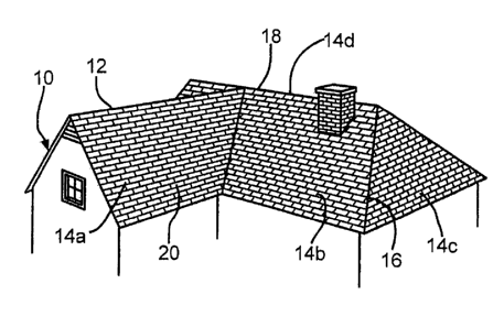
[0008] Fig. 1 is a perspective view of a building structure incorporating
hip
and ridge roofing shingles in accordance with embodiments of this invention.
[0009] Fig. 2 is a perspective view of the installation of the hip and
ridge
roofing shingles of Fig. 1.
[0010] Fig. 3 is a perspective view of a shingle blank used for making the
hip and ridge roofing shingles of Fig. 2.
[0011] Fig. 4 is a side view in elevation of an overlay portion of the
shingle
blank of Fig. 3.
[0012] Fig. 5 is an enlarged cross-sectional view, taken along the line 5-5
of
Fig. 3, of a portion of the hip and ridge roofing shingle of Fig. 3.
[0013] Fig. 6 is a plan view of an apparatus for manufacturing the shingle
blank of Fig. 3.
[0014] Fig. 7 is a side view in elevation of a second embodiment of an
overlay portion.
[0015] Fig. 8 is a perspective view of a second embodiment of a shingle
blank incorporating the overlay portion of Fig. 7.
[0016] Fig. 9 is a plan view of a third embodiment of an overlay portion
illustrated in a pre-folded condition.
[0017] Fig. 10 is a perspective view of the overlay portion of Fig. 9
illustrating the folding of the overlay portion.
[0018] Fig. 11 is a plan view of a second embodiment of an apparatus for
manufacturing the shingle blank of Fig. 8.
DETAILED DESCRIPTION OF THE INVENTION
[0019] The present invention will now be described with occasional
reference to the specific embodiments of the invention. This invention may,
however, be embodied in different forms and should not be construed as limited
3
= CA 02729373 2011-01-27
26669
to the embodiments set forth herein. Rather, these embodiments are provided
so that this disclosure will be thorough and complete, and will fully convey
the
scope of the invention to those skilled in the art.
[0020] Unless otherwise defined, all technical and scientific terms used
herein have the same meaning as commonly understood by one of ordinary skill
in the art to which this invention belongs. The terminology used in the
description of the invention herein is for describing particular embodiments
only and is not intended to be limiting of the invention. As used in the
description of the invention and the appended claims, the singular forms "a,"
"an," and "the" are intended to include the plural forms as well, unless the
context clearly indicates otherwise.
[0021] Unless otherwise indicated, all numbers expressing quantities of
dimensions such as length, width, height, and so forth as used in the
specification and claims are to be understood as being modified in all
instances
by the term "about." Accordingly, unless otherwise indicated, the numerical
properties set forth in the specification and claims are approximations that
may
vary depending on the desired properties sought to be obtained in embodiments
of the present invention. Notwithstanding that the numerical ranges and
parameters setting forth the broad scope of the invention are approximations,
the numerical values set forth in the specific examples are reported as
precisely
as possible. Any numerical values, however, inherently contain certain errors
necessarily resulting from error found in their respective measurements.
[0022] In accordance with embodiments of the present invention, hip and
ridge roofing shingles, and methods to manufacture the hip and ridge roofing
shingles, are provided. It will be understood the term "ridge" refers to the
intersection of the uppermost sloping roof planes. The term "roof plane" is
defined to mean a plane defined by a flat portion of the roof formed by an
area
of roof deck. The term "hip" is defined to mean the intersection of sloping
roof
planes located below the ridge. It will be understood the term "slope" is
4
= CA 02729373 2011-01-27
26669
defined to mean the degree of incline of a roof plane. The term "granule" is
defined to mean particles that are applied to a shingle that is installed on a
roof.
[0023] The description and figures disclose hip and ridge roofing shingles
for a roofing system and methods of manufacturing the hip and ridge roofing
shingles. Referring now to Fig. 1, a building structure 10 is shown having a
shingle-based roofing system 12. While the building structure 10 illustrated
in
Fig. 1 is a residential home, it should be understood that the building
structure
can be any type of structure, such as a garage, church, arena, industrial or
commercial building, having a shingle-based roofing system 12.
[0024] The building structure 10 has a plurality of roof planes 14a-14d.
The
roof planes 14a-14d can have a slope. While the roof planes 14a-14d shown in
Fig. 1 have their respective illustrated slopes, it should be understood that
the
roof planes 14a-14d can have any desired slope. The intersection of the roof
planes 14b and 14c form a hip 16. Similarly, the intersection of the roof
planes
14b and 14d form a ridge 18. The building structure 10 is covered by the
roofing system 12 having a plurality of shingles 20.
[0025] Referring now to Fig. 2, the shingles 20 are installed on the
various
roof planes 14a-14d in generally horizontal courses 22a-22g in which the
shingles 20 overlap the shingles 20 of a preceding course. The shingles 20
shown in Figs. 1 and 2 can be any desired shingle.
[0026] Hip and ridge roofing shingles are installed to protect hips and
ridges
from the elements. As shown in Fig. 2, hip and ridge roofing shingles 24 are
installed in an overlapping manner on the ridge 18 and over the shingles 20.
In
a similar fashion, hip and ridge roofing shingles (not shown) are installed on
a
hip and over the shingles. The method of installing the hip and ridge roofing
shingles 24 will be discussed in more detail below.
[0027] Referring now to Fig. 3, hip and ridge roofing shingles 24 are made
from a shingle blank 26. The shingle blank 26 includes an underlay portion 27
and an overlay portion 32. As will be discussed in more detail below, the
5
CA 02729373 2011-01-27
26669
underlay portion 27 and the overlay portion 32 can be formed from the same
granule-covered, asphalt-coated substrate material, separated from each other
and subsequently adhered together. The shingle blank 26 has a leading edge
87. The underlay portion 27 has an upper surface 28, a lower surface 29, an
upper edge 30 and a lower edge 31.
[0028] Referring again to Fig. 3, the shingle blank 26 may have any desired
dimensions. For example, a typical residential roofing shingle blank 26 has a
length L of approximately 36 inches (91.5 cm) and a height HI in a range of
from about 14.0 inches (35.6 cm) to about 18.0 inches (45.7 cm) high.
However, it will be understood that other desired lengths L and heights H1 can
be used.
[0029] As shown in Fig. 3, the shingle blank 26 includes first and second
perforation lines, 36 and 38. As will be discussed in more detail below, the
first and second perforation lines, 36 and 38, are configured to allow
separation
of the shingle blank 26 into pieces, thereby forming hip and ridge roofing
shingles 24.
[0030] Referring again to Fig. 3, the overlay portion 32 extends
substantially
across the length L of the shingle blank 26. The term "substantially" as used
herein, is defined to mean any desired distance in a range of from between
approximately one-half of the length L to the full length L.
[0031] Referring now to Fig. 4, the overlay portion 32 includes an upper
segment 40 and a lower segment 41. As will be explained in more detail below,
the upper segment 40 and the lower segment 41 are formed from a continuous
substrate coated with an asphalt coating and the coating itself is
subsequently
coated with granules. In the embodiment shown in Fig. 4, the upper segment
40 and the lower segment 41 combine to form a substantially flattened U-
shaped cross-sectional shape. However, the overlay portion 32 can form other
desired cross-sectional shapes.
6
[0032] Referring again to Fig. 4, a sealant bead 43 is positioned between
the
upper segment 40 and the lower segment 41. The sealant bead 43 is configured
to provide an adhesive seal between the upper and lower segments, 40 and 41.
The sealant bead 43 can be any suitable sealant or adhesive and can be applied
in any form or configuration in any location between the upper segment 40 and
the lower segment 41. In one embodiment, the sealant bead 43 can be a single
continuous strip or a plurality of continuous strips. In other embodiments,
the
sealant bead 43 can have a constant width or a varying width. In still other
embodiments, the sealant bead 43 can be a single discontinuous strip or a
plurality of discontinuous strips having varying widths. One example of a
sealant bead is the sealant line of the type disclosed in U.S. Patent No.
4,738,884 to Algrim et al.
[0033] Referring again to Fig. 4, the upper segment 40 has a length LUS and
the lower segment 41 has a length LLS. In the illustrated embodiment, the
lengths LUS and LLS of the upper and lower segments, 40 and 41, are in a
range of from about 4.0 inches to about 10.0 inches. However, in other
embodiments, the lengths LUS and LLS can be different. While the lengths
LUS and LLS are shown in the current embodiment as being the same, it should
be appreciated that the lengths LUS and LLS can be different from each other.
[0034] As shown in Fig. 4, the overlay portion 32 can include an optional
overlay perforation line 42. As will be described in more detail below, the
overlay perforation line 42 is configured to facilitate folding of a granule
and
asphalt coated substrate.
[0035] Referring now to Fig. 5, an enlarged cross-sectional view of a
portion
of the underlay portion 27 and a portion of the overlay portion 32 are
illustrated. Referring first to the underlay portion 27, a substrate 44 is
coated
with an asphalt coating 46. The substrate 44 can be any suitable substrate for
use in reinforcing asphalt-based roofing materials, including, but not limited
to
7
CA 2729373 2017-06-19
CA 02729373 2011-01-27
26669
a nonwoven web, scrim or felt of fibrous materials such as glass fibers,
mineral
fibers, cellulose fibers, rag fibers, mixtures of mineral and synthetic
fibers, or
the like. Combinations of materials can also be used in the substrate 44.
[0036] The asphalt coating 46 includes an upper region 48 that is
positioned
above the substrate 44 when the roofing material is installed on a roof, and a
lower region 50 that is positioned below the substrate 44. The upper region 48
includes an upper surface 52. The term "asphalt coating" means any type of
bituminous material suitable for use on a roofing material, including, but not
limited to asphalts, tars, pitches, or mixtures thereof. The asphalt can be
either
manufactured asphalt produced by refining petroleum or naturally occurring
asphalt. The asphalt coating 46 can include various additives and/or
modifiers,
such as inorganic fillers or mineral stabilizers, organic materials such as
polymers, recycled streams, or ground tire rubber.
[0037] A layer of granules 54 is pressed into the upper surface 52 of the
upper region 48. The granules 54 can be any desired granules or combination
of granules. Some examples of granules include prime, headlap granules or
waste granules. Optionally, the lower region 50 can be coated with any desired
backdust material 56.
[0038] Referring again to Fig. 5, the overlay portion 32 includes an
overlay
substrate 64 coated with an overlay asphalt coating 66. The overlay asphalt
coating 66 includes an overlay upper region 68 and an overlay lower region 70.
The overlay upper region 68 includes an overlay upper surface 72. A layer of
overlay granules 74 is pressed into the overlay upper surface 72 of the
overlay
upper region 68. Optionally, the overlay lower region 70 can be coated with
any desired overlay backdust material (not shown). In the illustrated
embodiment, the overlay substrate 64, overlay asphalt coating 66, overlay
upper
and lower regions, 68 and 70, overlay upper surface 72, overlay granules 74
and overlay backdust material are the same as, or similar to the substrate 44,
asphalt coating 46, upper and lower regions, 48 and 50, upper surface 52,
8
CA 02729373 2011-01-27
26669
granules 54 and backdust material 56 illustrated for the underlay portion 27
and
discussed above. Alternatively, the overlay substrate 64, overlay asphalt
coating 66, overlay upper and lower regions, 68 and 70, overlay upper surface
72, overlay granules 74 and overlay backdust material can be different.
[0039] As shown in Fig. 5, the overlay portion 32 is adhered to the
underlay
portion 27 by an adhesive material 80 such that the lower segment 41 of the
overlay portion 32 is attached to the upper surface 52 of the underlay portion
27. The adhesive material 80 is configured to provide an adhesive seal between
the overlay portion 32 and the underlay portion 27. The adhesive material 80
can be any suitable adhesive and can be applied in any form or configuration
in
any location between the overlay portion 32 and the underlay portion 27. The
manufacturing process of forming the overlay portion 32 and adhesion of the
overlay portion 32 to the underlay portion 27 will be discussed in more detail
below.
[0040] Referring again to Fig. 3, the shingle blank 26 includes the first
and
second perforation lines 36 and 38. The first and second perforation lines, 36
and 38, include perforations 82. The first and second perforation lines, 36
and
38, are spaced apart substantially perpendicular to the lower edge 31 of the
shingle blank 26 and span the height H1 of the shingle blank 26. The first and
second perforation lines, 36 and 38, are positioned such that subsequent
separation of the shingle blank 26 along the first and second perforation
lines,
36 and 38, forms hip and ridge roofing shingles 24. In the illustrated
embodiment, the formed hip and ridge roofing shingles 24 have a width WM.
In the illustrated embodiment, the width WM of the hip and ridge roofing
shingles 24 is approximately 12.0 inches. In other embodiments, the width
WM of the hip and ridge roofing shingles 24 can be more or less than
approximately 12.0 inches. While in the illustrated embodiment, the width WM
of the formed hip and ridge roofing shingles 24 are the same, in other
9
CA 02729373 2011-01-27
26669
embodiments, the hip and ridge roofing shingles 24 can have different widths
WM from each other.
[0041] As shown in Fig. 3, the underlay portion 27 has a height H2 and the
overlay portion 32 has a height H3. In the illustrated embodiment, the heights
H2 and H3 are in a range of from about 4.0 inches (10.1 cm) to about 10.0
inches (25.4 cm). However, it should be understood that in other embodiments
the heights H2 and H3 can be less than about 4.0 inches (10.1 cm) or more than
about 10.0 inches (25.4 cm). It should also be understood that although the
illustrated embodiment shows the heights H2 and H3 to be the same, in other
embodiments, the heights H2 and H3 can be different from each other.
[0042] Referring again to Fig. 3, the underlay portion 27 and the overlay
portion 32 overlay in an overlap region 83. The overlay region 83 has a height
H4. In the illustrated embodiment, the height H4 of the overlay region is in a
range of from about 2.0 inches (5.1 cm) to about 4.0 inches (10.2 cm).
Alternatively, in other embodiments the height H4 can be less than about 2.0
inches (5.1 cm) or more than about 4.0 inches (10.2 cm).
[0043] As further shown in Fig. 3, the hip and ridge roofing shingles 24
have a headlap region 58 and a prime region 59. The headlap region 58 of the
hip and ridge roofing shingles 24 is the portion of the hip and ridge roofing
shingles 24 that is covered by successive overlapping hip and ridge roofing
shingles 24 when the hip and ridge roofing shingles 24 are installed. The
prime
region 59 of the shingle blank 26 is the portion of the hip and ridge roofing
shingles 24 that remains substantially exposed when the hip and ridge roofing
shingles 24 are installed.
[0044] Referring again to Fig. 3, the height H1 of the shingle blank 26 may
be divided between the headlap region 58 and the prime region 59 in any
suitable proportion. In one embodiment, the height of the headlap region 58
can be approximately 2 inches (5.1 cm) greater than the height of the prime
CA 02729373 2011-01-27
26669
region 59. Alternatively, the height of the headlap region 58 can be more or
less than 2 inches greater than the height of the prime region 59.
[0045] Referring again to Fig. 3, the perforations 82 extend through the
various layers of the underlay portion 27 and the overlay portion 32. In other
embodiments, the perforations 82 can extend through any desired layers of the
underlay portion 27 and the overlay portion 32. The perforations 82 can be
arranged in any suitable pattern to form the first and second perforation
lines,
36 and 38.
[0046] In one example of a perforation pattern, the perforations 82 can be
about 0.25 inches long and spaced apart from edge to edge by about 0.25
inches. In another embodiment of a perforation pattern, the perforations 82
can
be about 0.50 inches long and spaced apart from edge to edge about 0.50
inches. Alternatively, the perforations 82 can be any suitable length and can
be
spaced apart edge to edge by any suitable length. The perforations 82 are
configured such that an installer is able to separate the shingle blanks 26
into
the hip and ridge roofing shingles 24 at the installation site. In the
illustrated
embodiment, the first and second perforation lines, 36 and 38, extend the full
height H1 of the shingle blank 26. Alternatively, the first and second
perforation lines, 36 and 38, can extend any height sufficient to enable an
installer to separate the shingle blanks 26 into the hip and ridge roofing
shingles
24 at an installation site. While the embodiment shown in Fig. 3 illustrates a
quantity of two perforation lines, 36 and 38, it should be understood that
more
or less than two perforation lines, sufficient to enable an installer to
separate the
shingle blanks 26 into the hip and ridge roofing shingles 24, can be used.
[0047] Referring again to Fig. 3, the shingle blanks 26 arrive at the
installation site having first and second perforation lines 36 and 38. During
installation, the roofing installer separates the shingle blank 26 along the
first
and second perforation lines, 36 and 38 to form hip and ridge roofing shingles
24. The perforations 82 allow for the hip and ridge roofing shingles 24 to be
11
CA 02729373 2011-01-27
26669
formed from the shingle blanks 26 as the perforations 82 allow the various
layers of the underlay portion 27 and the overlay portion 32 to be readily
separated. The hip and ridge roofing shingles 24 have perforated edges 84.
The configuration of the perforations 82 result in a perforated edge 84 which
in
some embodiments can be somewhat ragged. As one example, if the individual
perforations 82 have a relatively long length or if a larger quantity of
perforations 82 are used, then the perforation edges 84 are somewhat smoother.
Conversely, if the individual perforations 82 have a relatively short length
or if
a fewer number of perforations 82 are used, then the perforation edges 84 are
somewhat more ragged.
[0048] Referring again to Fig. 3, optionally a plurality of headlap
courtesy
cuts 60a extend from the leading edge 87 and a plurality of prime courtesy
cuts
60b extend from the lower edge 31 of the underlay portion 27. In the
illustrated
embodiment, the headlap courtesy cuts 60a are configured to substantially
align
with a corresponding prime courtesy cut 60b, and the aligned headlap and
prime courtesy cuts, 60a and 60b, are further aligned along the perforation
lines, 36 and 38. As shown in the illustrated embodiment, the headlap courtesy
cuts 60a and the prime courtesy cuts 60b extend substantially through the
thickness of the shingle blank 26. In other embodiments, the courtesy cuts,
60a
and 60b, can extend through any suitable layers of the shingle blank 26. The
headlap and prime courtesy cuts, 60a and 60b, have a length. In the
illustrated
embodiment, the length of the headlap and prime courtesy cuts, 60a and 60b, is
in a range of from about 1.0 inches to about 5.0 inches. In other embodiments,
the length of the headlap and prime courtesy cuts, 60a and 60b, can be less
than
about 1.0 inches or more than about 5.0 inches. While the illustrated
embodiment shows the headlap courtesy cuts 60a and the prime courtesy cuts
60b as being the same length, it should be understood that headlap courtesy
cuts
60a and the prime courtesy cuts 60b can be different lengths.
12
CA 02729373 2011-01-27
26669
100491 As shown in Fig. 3, optionally a plurality of overlay courtesy cuts
61
are positioned in the overlay region 83 and extend substantially through the
overlay portion 32 and the underlay portion 27. In the illustrated embodiment,
the overlay courtesy cuts 61 are configured to substantially align with a
corresponding prime courtesy cut 60b, and the aligned headlap and prime
courtesy cuts, 60a and 60b, are further aligned along the perforation lines,
36
and 38. As shown in the illustrated embodiment, the overlay courtesy cuts 61
extend substantially through the layers of the overlay region 83. In other
embodiments, the overlay courtesy cuts 61 can extend through any desired
layers of the overlay region 83. The overlay courtesy cuts 61 have a length.
In
the illustrated embodiment, the length of the overlay courtesy cuts 61 is in a
range of from about 1.0 inches to about 5.0 inches. In other embodiments, the
length of the overlay courtesy cuts 61 can be less than about 1.0 inches or
more
than about 5.0 inches. While the illustrated embodiment shows the overlay
courtesy cuts 61 as being the same length, it should be understood that the
overlay courtesy cuts 61 can be different lengths.
[0050] The courtesy cuts, 60a and 60b, are configured to assist the
installer
in separating the shingle blanks 26. As will be explained below in more
detail,
the courtesy cuts, 60a and 60b, are provided in the shingle blank 26 during
the
manufacture of the shingle blank 26.
100511 Referring again to Fig. 2, the hip and ridge roofing shingles 24 are
installed in an overlapping manner on the ridge 18 and over the shingles 20.
As
a first installation step, an underlay portion 27 and the connected overlay
portion 32 are cut from a hip and ridge roofing shingle 24 and fastened to the
farthest downwind point on the ridge 18. As shown in Fig. 2, the direction of
the prevailing wind in indicated by the arrow marked W. The overlay portion
32 can be fastened by any desired fastening method, such as for example,
roofing nails (not shown). Next, a hip and ridge roofing shingle 24 is
installed
over the overlay portion 32 such that a portion of the hip and ridge roofing
13
CA 02729373 2011-01-27
26669
shingle 24 overlaps the overlay portion 32 and the leading edge 87 of the hip
and ridge roofing shingle 24 is facing the wind direction W. The hip and ridge
roofing shingle 24 is fastened to the ridge 18 in any desired manner.
Additional
hip and ridge roofing shingles 24 are installed in a similar fashion until the
ridge 18 is covered.
[0052] Referring now to Fig. 6, an apparatus 100 for manufacturing shingle
blanks 26 is illustrated. Generally, the manufacturing process involves
passing
a continuous sheet 102 in a machine direction (indicated by the arrow DO
through a series of manufacturing operations. In the illustrated embodiment,
the sheet 102 usually moves at a speed of at least about 200 feet/minute (61
meters/minute), and typically at a speed within the range of between about 450
feet/minute (137 meters/minute) and about 800 feet/minute (244
meters/minute). The continuous sheet 102, however, may move at other desired
speeds.
[0053] In the illustrated embodiment, the continuous sheet 102 has the same
granule-covered, asphalt-coated substrate structure as the underlay portion 27
shown in Fig. 5 and as described above. However, the continuous sheet 102
can have other desired structure. The continuous sheet 102 can be
manufactured with any desired manufacturing process.
[0054] The continuous sheet 102 includes a plurality of lanes 106, 108,
110,
112, 114, 116, 118 and 120. As will be explained in more detail below, the
lanes 106 and 108 will be separated from the continuous sheet 102 and formed
into a first overlay portion. The first overlay portion will then be adhered
to a
remaining portion of the continuous sheet to form the shingle blanks.
Similarly, the lanes 118 and 120 will be separated from the continuous sheet
102 and formed into a second overlay portion. The second overlay portion will
then be adhered to another remaining portion of the continuous sheet to form
the shingle blanks.
14
CA 02729373 2011-01-27
26669
[0055] In the illustrated embodiment, the lanes 106, 108, 110, 116, 118 and
120 are covered with headlap granules and will form the headlap region 58 of
the hip and ridge roofing shingles 24 as shown in Fig. 3. The lanes 112 and
114 are covered with prime granules and will form the prime region 59 of the
hip and ridge roofing shingles 24 as shown in Fig. 3.
[0056] Referring again to Fig. 6, in a first step of the illustrated
manufacturing process, the continuous sheet 102 is fed in machine direction DI
through a cutting assembly 126. The cutting assembly 126 is configured to
perform several manufacturing operations. First, the cutting assembly 126 is
configured to form a perforation line (not shown) between lanes 106 and 108.
Similarly, the cutting assembly 126 is configured to form a perforation line
(not
shown) between lanes 118 and 120. The perforation lines between lanes 106
and 108 and between lanes 118 and 120 are configured to facilitate folding of
lanes 106 and 108 and folding of lanes 118 and 120 in downstream operations.
Second, the cutting assembly 126 is configured to separate lanes 106 and 108
from the continuous sheet 102. Similarly, the cutting assembly 126 is
configured to separate lanes 118 and 120 from the continuous sheet 102.
Finally, the cutting assembly 126 is configured to separate lanes 112 and 114
from each other. As will be discussed in more detail below, lanes 112 and 114
will form underlay portion 27 as described above and shown in Fig. 3. In the
illustrated embodiment, the cutting assembly 126 includes one or more cutting
or perforation rollers. In other embodiments, the cutting assembly 126 can be
other structures, mechanisms or devices configured to form perforations and
separate lanes from the continuous sheet 102. After separation from the
continuous sheet 102, lanes 106 and 108 form pre-folded lanes, 130a and 130b,
and separated lanes 118 and 120 form pre-folded lanes 132a and 132b.
[0057] As shown in Fig. 6, lanes 110 and 112, now separated from the
continuous sheet 102 form a first underlay portion 27a. Similarly, lanes 114
and 116, now separated from the continuous sheet 102 form a second underlay
CA 02729373 2011-01-27
26669
portion 27b. The pre-fold lanes 130a, 130b, 132a and 132b, and the first and
second underlay portions 27a and 27b continue in machine direction Dl.
[0058] In a next step of the manufacturing process, the pre-folded lanes
130a and 130b are fed through a first applicator 128a. Similarly, the pre-
folded
lanes 132a and 132b are fed through a second applicator 128b. The first and
second applicators, 128a and 128b, are configured to apply the sealant bead
43,
discussed above and shown in Figs. 3 and 4, to a bottom surface of one of the
pre-folded lanes 130a or 130b and one of the pre-folded lanes 132a or 132b.
The first and second applicators, 128a and 128b, can be any suitable
structure,
mechanism, device or combination thereof configured for application of the
sealant bead 43 to one of the pre-folded lanes 130a or 130b and one of the pre-
folded lanes 132a or 132b. Application of the sealant beads 43 to the pre-
folded lanes 130a or 130b and 132a or 132b forms beaded pre-folded lanes
134a, 134b, 136a and 136b. The beaded pre-folded lanes 134a, 134b, 136a and
136b and the first and second underlay portions 27a and 27b continue in
machine direction Dl.
[0059] The beaded pre-folded lanes 134a and 134b are fed through a first
folder 142a. Similarly, the beaded pre-folded lanes 136a and 136b are fed
through a second folder 142b. The first folder 142a is configured to bend or
fold the beaded pre-folded lanes 134a and 134b about the perforation line
between the beaded pre-folded lanes, 134a and 134b, thereby forming a first
overlay portion 32a. Similarly, the second folder 142b is configured to bend
or
fold the beaded pre-folded lanes 136a and 136b about the perforation line
between the beaded pre-folded lanes 136a and 136b, thereby forming a second
overlay portion 32b. The first and second overlay portions, 32a and 32b, have
the same structure as the overlay portion 32 discussed above and illustrated
in
Fig. 4. In the embodiment illustrated in Fig. 6, the first folder 142a
includes at
least one folding shoe (not shown) configured to fold the beaded pre-folded
lanes 134a and 134b together such that the granule covered surfaces of beaded
16
CA 02729373 2011-01-27
26669
pre-folded lanes 134a and 134b are on the outer surfaces of the first overlay
portion 32a. Similarly, the second folder 142b includes at least one folding
shoe (not shown) configured to fold beaded pre-folded lanes 136a and 136b
together such that the granule covered surfaces of beaded pre-folded lanes
136a
and 136b are on the outer surfaces of the second overlay portion 32b. While
the first and second folders, 142a and 142b, have been described above an
having at least one folding shoe, it should be understood that in other
embodiments, the first and second folders, 142a and 142b, can be other
structures, mechanisms, devices or combinations thereof, sufficient to bend or
fold the beaded pre-folded lanes 134a, 134b and 136a, 136b into first and
second overlay portions 32a and 32b.
[0060] As described above, the first and second folders, 142a and 142b,
fold
the beaded pre-folded lanes 134a, 134b and 136a, 136b into first and second
overlay portions 32a and 32b. The first and second overlay portions, 32a and
32b, and the first and second underlay portions, 27a and 27b, advance in
machine direction Dl.
[0061] Referring again to Fig. 6, the first overlay portion 32a is fed
through
a third applicator 150. The third applicator 150 is configured for several
manufacturing operations. First, the third applicator 150 is configured to
adhere the first overlay portion 32a to a portion of the first underlay
portion 27a
using the adhesive 80 illustrated in Fig. 5 and described above. Similarly,
the
third applicator 150 is configured to adhere the second overlay portion 32b to
a
portion of the second underlay portion 27b using the adhesive 80. The third
applicator 150 can be any suitable structure, mechanism, device or combination
thereof configured for adhesion of the first and second overlay portions, 32a
and 32b, to a portion of the first and second underlay portions 27a and 27b.
Application of the first and second overlay portions, 32a and 32b, to the
first
and second underlay portions, 27a and 27b, forms first and second applied
sheets, 156a and 156b. Applied sheet 156a includes lanes 110 and 112 and
17
CA 02729373 2011-01-27
26669
adhered first overlay portion 27a. Similarly, applied sheet 156b includes
lanes
114 and 116 and adhered second overlay portion 27b.
[0062] In a next manufacturing operation as shown in Fig. 6, the first and
second applied sheets, 156a and 156b, are fed through a fourth applicator 160.
The fourth applicator 160 is configured to apply an optional sealant bead 162
to
a portion of the lower surface 29 of the shingle blank 26 as shown in Fig. 3.
In
one embodiment, the sealant bead 162 can be the same as, or similar to, the
sealant bead 43 illustrated in Fig. 4 and described above. However, the
sealant
bead 162 can be different.
[0063] Referring again to Fig. 6, the fourth applicator 160 is also
configured
to apply an optional release tape 164 to a portion of a lower surface of the
overlay portion 32 as shown in Fig. 8. The release tape 164 is positioned on
the
lower surface of the overlay portion 32 in a location suitable to cover the
optional sealant line 162 as the shingle blanks 26 are stacked for storage or
shipping. In the illustrated embodiment, the release tape 164 is made of a
polymeric material. In other embodiments, the release tape 164 can be made of
other desired materials or combinations of materials. In still other
embodiments, the release tape 164 can have desired coatings. The release tape
164 can have any configuration, orientation and dimensions suitable to cover
the optional sealant line 162 as the shingle blanks 26 are stacked for storage
or
shipping. However, configuring the shingle blank 26 to include a release tape
164 is optional and not necessary for the use of the shingle blank 26.
[0064] Application of the optional sealant bead 162 and the optional
release
tape 164 to the first and second applied sheets, 156a and 156b, forms first
and
second pre-cut sheets 166a and 166b. The first pre-cut sheet 166a includes
lanes 110 and 112 of the underlay portion 27a, adhered first overlay portion
32a, optional sealant bead 162 and optional release tape 164. Similarly, the
second pre-cut sheet 166b includes lanes 114 and 116 of the underlay portion
18
CA 02729373 2011-01-27
26669
27b, adhered second overlay portion 32b, optional sealant bead 162 and
optional release tape 164.
100651 The first and second pre-cut sheets, 166a and 166b, are passed
through a cutting mechanism 170. The cutting mechanism 170 is configured to
perform several manufacturing operations. First, the cutting mechanism 170 is
configured to form perforation lines, 36 and 38, having perforations 82 as
described above and illustrated in Fig. 3. The cutting mechanism 170 can form
the perforation 82 in any desired manner. Second, the cutting mechanism 170
is configured to cut the first and second pre-cut sheets, 166a and 166b,
thereby
forming the individual shingle blanks 26. The shingle blanks 26 have the
underlay portion 27 and the overlay portion 32. While Fig. 6 illustrates one
example of an apparatus 170 configured for forming the perforations 82 and
cutting the individual shingle blanks 26, it should be understood that other
suitable mechanisms or combinations of mechanisms can be used.
100661 The shingle blanks 26 can be collected and packaged such that the
release tape 164 positioned on the lower surface of the overlay portion 32
covers the optional sealant line 162 located on the lower surface 29 of a
subsequent shingle blank 26. While the embodiment shown in Fig. 6 illustrates
the perforating and cutting processes as a single process, it is within the
contemplation of this invention that the perforating and cutting processes can
be completed at different times and by different apparatus.
[0067] While the apparatus 100 is shown and described in terms of a
continuous process, it should be understood that the manufacturing method can
also be practiced in a batch process using discreet lengths of materials
instead
of continuous sheets.
[0068] While the embodiment illustrated in Figs. 3-6 describe an overlay
portion having a substantially flattened U-shaped cross-sectional shape and
positioned to overlap a portion of the underlay sheet, in other embodiments,
the
19
CA 02729373 2011-01-27
26669
overlay portion can have other cross-sectional shapes and can be positioned in
other locations on the underlay sheet.
[0069] Referring now to Fig. 7, a second embodiment of an overlay portion
232 is illustrated. The overlay portion 232 includes an upper segment 240, a
lower segment 241 and an intermediate segment 242. In the illustrated
embodiment, the upper segment 240 and the lower segment 241 are the same
as, or similar to, the upper segment 40 and the lower segment 41 described
above and illustrated in Fig. 4. Alternatively, the upper segment 240 and the
lower segment 241 can be different from the upper segment 40 and the lower
segment 41. The intermediate segment 242 is formed from the same
continuous substrate coated with an asphalt coating subsequently coated with
granules as forms the upper and lower segments, 240 and 241. In the
embodiment shown in Fig. 7, the upper segment 240, lower segment 241 and
intermediate segment 242 of the overlay portion 232 combine to form a U-
shaped cross-sectional shape. However, the overlay portion 232 can form other
desired cross-sectional shapes.
[0070] Referring again to Fig. 7, a sealant bead 243 is positioned between
the upper segment 240 and the lower segment 241. In the illustrated
embodiment, the sealant bead 243 is the same as or similar to the sealant bead
43 described above and illustrated in Fig. 4. In other embodiments, the
sealant
bead 243 can be different from the sealant bead 43.
[0071] As shown in Fig. 7, the upper segment 240 has a length LUS2, the
lower segment 241 has a length LLS2, and the intermediate segment 242 has a
length US. In the illustrated embodiment, the lengths LUS2 and LLS2 of the
upper and lower segments, 240 and 241 respectively, are approximately 4.0
inches and the length US of the intermediate segment 242 is approximately
0.50 inches. However, in other embodiments, the lengths LUS2, LLS2 and US
can be different. While the lengths LUS2 and LLS2 are shown in the current
CA 02729373 2011-01-27
26669
embodiment as being the same, it should be appreciated that the lengths LUS2
and LLS2 can be different from each other.
100721 As discussed above, the overlay portion 232 can be positioned on an
underlay portion in any desired location. Fig. 8 illustrates one embodiment of
the positioning of the overlay portion 232 on an underlay portion 227, thereby
forming shingle blank 226. The shingle blank 226 includes the overlay portion
232 adhered to the underlay portion 227. An optional sealant bead 262 and an
optional release tape 264 are positioned on a lower surface 229 of the
underlay
portion 227. As further shown in Fig. 8, the shingle blank 226 includes first
and second perforation lines 236 and 238 and a leading edge 287. The overlay
portion 232 includes a sealant bead 243 positioned between the upper segment
240, the lower segment 241 and the intermediate segment 242. In the
illustrated embodiment, the optional sealant bead 262, optional release tape
264, lower surface 229, and first and second perforation lines, 236 and 238,
are
the same as, or similar to the optional sealant bead 162, optional release
tape
164, lower surface 29, and first and second perforation lines, 36 and 38,
discussed above and illustrated in Fig. 3. However, the optional sealant bead
262, optional release tape 264, lower surface 229, and first and second
perforation lines, 236 and 238, can be different from the optional sealant
bead
162, optional release tape 164, lower surface 29, and first and second
perforation lines, 36 and 38.
[0073] Referring again to Fig. 8, the overlay portion 232 is offset from
the
leading edge 287 of the shingle blank 226 thereby forming an offset segment
290. The offset segment has an offset length OL. In the illustrated
embodiment, the offset length OL is in a range of from about 0.25 inches to
about 2.0 inches. In other embodiments, the offset length OL can be less than
about 0.25 inches or more than about 2.00 inches. The offset segment 290 is
configured to provide an additional shingle layer under subsequent overlapping
hip and ridge shingle shingles 24 as shown in Fig. 2. While the embodiment
21
CA 02729373 2011-01-27
26669
illustrated in Fig. 8 illustrates the overlay portion 232 as being positioned
substantially adjacent to the leading edge 287 of the shingle blank 226, it
should be appreciated that the overlay portion 232 can be positioned in any
desired location on the underlay portion 227, such as the non-limiting example
of the center of the underlay portion 227.
[0074] The shingle blank 226 having the underlay portion 227 and the
overlay portion 232 illustrated in Fig. 8 can be manufactured and installed
using
the same manufacturing and installation processes described above and
illustrated in Figs. 2 and 6. In other embodiments, the shingle blank 226,
underlay portion 227 and the overlay portion 232 can be manufactured or
installed using other manufacturing or installation processes.
[0075] While the lower segments 41 and 241 of the overlay portions 32 and
232 described above and illustrated in Figs. 4 and 7 are formed from a
continuous granule and asphalt coated substrate, it should be appreciated that
in
other embodiments, the lower segment can include cutouts advantageously
configured to reduce the weight of the hip and ridge shingles.
[0076] Referring now to Figs. 9 and 10 another embodiment of an overlay
portion 332 is illustrated. The overlay segment 332 includes an upper segment
340 and a lower segment 341. The lower segment 341 includes a plurality of
cutout portions 392. As shown in Fig. 9, the upper segment 340 and the lower
segment 341 having the cutout portions 392 are folded together thereby forming
the overlay portion 332. In the illustrated embodiment, the overlay portion
332
is the same as, or similar to, the overlay portion 32 illustrated in Fig. 3
and
described above. The cutouts 392 advantageously reduce the material weight
of the resulting shingle blanks, thereby reducing shipping and handling costs.
While the cutouts 392 illustrated in Figs. 9 and 10 have a rectangular shape
and
are equally spaced apart, it should be appreciated that the cutouts 392 can
have
other desired shapes and can have any desired spacing.
22
CA 02729373 2011-01-27
26669
[0077] Referring now to Fig. 11, an apparatus 400 for manufacturing shingle
blanks 26 having overlay portions with cutouts is illustrated. Generally, the
manufacturing process illustrated in Fig. 11 is the same as, or similar to the
manufacturing process illustrated in Fig. 6 with the additional operation of
forming the cutouts in the lower segments of the overlay portions.
[0078] In the illustrated embodiment, the continuous sheet 402 has the same
granule-covered, asphalt-coated substrate structure as the continuous sheet
102
shown in Fig. 6 and as described above. However, the continuous sheet 402
can have other desired structure.
[0079] The continuous sheet 402 includes a plurality of lanes 405, 406,
408,
410, 412, 414 and 415. As will be explained in more detail below, lane 410
will be formed into mating cutouts, which when combined with lanes 408 and
412 will form overlay portions. The overlay portions will be adhered to
underlay portions to form the shingle blanks.
[0080] In the illustrated embodiment, lanes 406, 408, 410, 412 and 414 are
covered with headlap granules and will form the headlap region 58 of the hip
and ridge roofing shingles 24 as shown in Fig. 3. Lanes 405 and 415 are
covered with prime granules and will form the prime region 59 of the hip and
ridge roofing shingles 24 as shown in Fig. 1
[0081] Referring again to Fig. 11, in a first step of the illustrated
manufacturing process, the continuous sheet 402 is fed in machine direction
D401 through an applicator 480. The applicator 480 is configured to apply
registration marks (not shown) to a portion of the lanes 408 and 412 in any
desired location relative to mating cutouts in lane 410 and in a direction
generally perpendicular to the machine direction D401. For example, in one
embodiment, the registration marks can indicate the center of a cutout. In
other
embodiments, the registration marks can indicate the center of a tooth. In
still
other embodiments, the registration marks can indicate any portion of a cutout
or a tooth. The applicator 480 can be any desired structure, device or
23
CA 02729373 2011-01-27
26669
mechanism sufficient to apply registration marks to the lanes 408 and 412. The
registration marks can be applied in any desired configuration including the
non-limiting examples of a series of spots or discontinuous lines. In some
embodiments, the registration marks can be paint. However, other forms of
registration marks can be used. In still other embodiments, the registration
marks can be used to indicate a nailing line for the formed shingle blanks. As
will be discussed in more detail below, the registration marks are configured
for
use as a timing registration in downstream operations. Application of the
registration marks to the lanes 408 and 412 forms marked sheet 482.
[0082] The marked sheet 482 is then fed in machine direction D401 through
a reader 484. The reader 484 is configured to read the location of the
registration marks applied to lanes 408 and 412 relative to the mating
cutouts.
The reader 484 can be any desired structure, device or mechanism sufficient to
read the location of registration marks on the marked sheet. In one
embodiment, the reader 484 is an infrared sensor, However, other readers can
be used. As will be explained in more detail below, the reader 484 retains the
read information for use in downstream operations. Reading of the marked
sheet 482 by the reader 484 forms read sheet 486.
[0083] Referring again to Fig. 11, in a next step of the illustrated
manufacturing process, the read sheet 486 is fed in machine direction D401
through a cutting assembly 426. The cutting assembly 426 is configured to
perform several manufacturing operations. First, the cutting assembly 426 is
configured to form a plurality of mating cutouts 492 in lane 410. The cutouts
492 are the same as or similar to the cutouts 392 described above and
illustrated
in Figs. 9 and 10. Second, the cutting assembly 426 is configured to form a
perforation line (not shown) between lane 408 and the material remaining in
lane 410. Similarly, the cutting assembly 426 is configured to form a
perforation line (not shown) between lane 412 and the material remaining in
lane 410. The perforation line between lane 408 and the material remaining in
24
CA 02729373 2011-01-27
26669
lane 410 is configured to facilitate folding of lane 408 with the material
remaining in lane 410 in downstream operations. Similarly, the perforation
line
between lane 412 and the material remaining in lane 410 is configured to
facilitate folding of lane 412 with the material remaining in lane 410 in
downstream operations. Finally, the cutting assembly 426 is configured to
separate the combined lanes 405 and 406 from the read sheet 486. Similarly,
the cutting assembly 426 is configured to separate the combined lanes 414 and
415 from the read sheet 486. As will be discussed in more detail below, lanes
405 and 406 and lanes 414 and 415 will form underlay portion 227 as described
above and shown in Fig. 8. In the illustrated embodiment, the cutting assembly
426 is the same as or similar to the cutting assembly 126 described above and
illustrated in Fig. 6. However, the cutting assembly 426 can be different from
the cutting assembly 126. After formation of the mating cutouts 492 and after
separation from the continuous sheet 402, lanes 408 and 410 form pre-folded
lanes, 430a and 430b, and separated lanes 410 and 412 form pre-folded lanes
432a and 432b.
[0084] As shown in Fig. 11, lanes 405 and 406, now separated from the
continuous sheet 402 form a first underlay portion 427a. Similarly, lanes 415
and 415, now separated from the continuous sheet 402 form a second underlay
portion 427b. The pre-fold lanes 430a, 430b, 432a and 432b, and the first and
second underlay portions 427a and 427b continue in machine direction D401.
[0085] In a next step of the manufacturing process, the pre-folded lanes
430a and 430b are fed through an applicator 428. Similarly, the pre-folded
lanes 432a and 432b are fed through the applicator 428. The applicator 428 is
configured to apply the sealant bead 243, discussed above and shown in Figs. 7
and 8, to a bottom surface of one of the pre-folded lanes 430a or 430b and one
of the pre-folded lanes 432a or 432b. In the illustrated embodiment, the
applicator 428 is the same as or similar to the applicators 128a and 128b
described above and illustrated in Fig. 6. Alternatively, the applicator 428
can
CA 02729373 2011-01-27
26669
be different from the applicators 128a and 128b. Application of the sealant
beads to the pre-folded lanes 430a or 430b and 432a or 432b forms beaded pre-
folded lanes 434a, 434b, 436a and 436b. The beaded pre-folded lanes 434a,
434b, 436a and 436b and the first and second underlay portions 427a and 427b
continue in machine direction Dl.
[0086] The beaded pre-folded lanes 434a and 434b are fed through a folder
442. Similarly, the beaded pre-folded lanes 436a and 436b are fed through the
folder 442. The folder 442 is configured to bend or fold the beaded pre-folded
lanes 434a and 434b about the perforation line between the beaded pre-folded
lanes, 434a and 434b, thereby forming a first overlay portion 438a. Similarly,
the folder 442 is configured to bend or fold the beaded pre-folded lanes 436a
and 436b about the perforation line between the beaded pre-folded lanes 436a
and 436b, thereby forming a second overlay portion 438b. The first and second
overlay portions, 438a and 438b, have the same structure as the overlay
portion
232 discussed above and illustrated in Figs. 7 and 8. In the embodiment
illustrated in Fig. 11, folder 442 is the same as or similar to the folders
142a and
142b discussed above and illustrated in Fig. 6. In other embodiments, the
folder 442 can be different from the folders 142a and 142b. The first and
second overlay portions, 438a and 438b, and the first and second underlay
portions, 427a and 427b, advance in machine direction D401.
100871 Referring again to
Fig. 11, the first overlay portion 438a and the first
underlay portion 427a are fed through applicator 450a. Applicator 450a is
configured to adhere the first overlay portion 438a to a portion of the first
underlay portion 427a using the adhesive 80 illustrated in Fig. 3 and
described
above. Similarly, the second overlay portion 438b and the second underlay
portion 427b are fed through applicator 45011 Applicator 450b is configured to
adhere the second overlay portion 438b to a portion of the second underlay
portion 427b using the adhesive 80. In the illustrated embodiment, the
applicators, 450a and 450b, are the same as or similar to the applicator 150
26
CA 02729373 2011-01-27
26669
described above and illustrated in Fig. 11. However, the applicators 450a and
450b can be different from the applicator 150. Application of the first and
'second overlay portions, 438a and 438b, to the first and second underlay
portions, 427a and 427b, forms first and second applied sheets, 456a and 456b.
100881 In additional downstream operations, optional sealant beads and
optional release tapes can be applied to the first and second applied sheets
456a
and 456b by the applicator 460. In the illustrated embodiment, the optional
sealant beads and the optional release tapes are the same as, or similar to,
the
sealant bead 262 and the release tape 264 described above and illustrated in
Fig.
8. In other embodiments, the optional sealant beads and the optional release
tapes can be different from the sealant bead 262 and the release tape 264. In
one embodiment, the applicator 460 is the same as or similar to the fourth
applicator 160 as illustrated in Fig. 6 and described above. In other
embodiments, the applicator 460 can be different from the fourth applicator
160.
[0089] Application of the optional sealant bead and the optional release
tape
to the first and second applied sheets, 456a and 456b, form first and second
pre-
cut sheets 466a and 466b.
100901 The first and second pre-cut sheets, 466a and 466b, are passed
through a reader 488. The reader 488 is configured to confirm the location of
the registration marks, applied by the applicator 480 to lanes 408 and 412 and
read previously by the reader 484, relative to the mating cutouts. Reading of
the first and second pre-cut sheets, 466a and 466b, forms read first and
second
pre-cut sheets 490a and 490b. The reader 488 can be the same as, or similar to
the reader 484 discussed above. Alternatively, the reader 488 can be different
from the reader 484.
[0091] The read first and second pre-cut sheets, 490a and 490b, are passed
through a cutting mechanism 470. The cutting mechanism 470 is configured to
perform several manufacturing operations. First, the cutting mechanism 470 is
27
CA 02729373 2011-01-27
26669
configured to form perforation lines, 236 and 238, having perforations 282 as
described above and illustrated in Fig. 8. Second, the cutting mechanism 470
is
configured to cut the read first and second pre-cut sheets, 490a and 490b,
thereby forming the individual shingle blanks 426a and 427b. The cutting
mechanism 470 uses information provided by the reader 488 as to the location
of the mating cutouts. The cutting mechanism 470 can be configured to cut the
read first and second pre-cut sheets, 490a and 490b, such that the cuts occur
at
any desired location along any cutout or at any desired location between any
cutout. In this manner, the cutting of the individual shingle blanks 426a and
427b is synchronized by the reader 488. In the illustrated embodiment, the
cutting mechanism 470 is the same as or similar to the cutting mechanism 170
described above and illustrated in Fig. 6. Alternatively, the cutting
mechanism
470 can be different from the cutting mechanism 170.
100921 In the embodiment illustrated in Fig. 11, the shingle blanks 426a
and
426b are collected and packaged as described above. In other embodiments,
the shingle blanks 426a and 426b can be collected and packaged in other
desired manners. One non-limiting example of stacking the shingle blanks,
426a and 426b, includes flipping alternate shingle blanks such that a face of
one shingle blank is in contact with the face of a subsequent shingle blank
and
the back of the subsequent shingle blank is in contact with the back of the
next
shingle blank. While the embodiment shown in Fig. 11 illustrates the
perforating and cutting processes as a single process, it is within the
contemplation of this invention that the perforating and cutting processes can
be completed at different times and by different apparatus.
100931 While the apparatus 400 is shown and described in terms of a
continuous process, it should be understood that the manufacturing method can
also be practiced in a batch process using discreet lengths of materials
instead
of continuous sheets.
28
CA 02729373 2011-01-27
26669
[0094] While the embodiment illustrated in Fig. 11 uses the applicator 480
to provide registration marks, it should be appreciated that the cutting of
the
shingle blanks 426a and 426b can be synchronized with other methods,
including the non-limiting example of using registration cutouts in the
headlap
lanes 408 and 410.
[0095] The principle and mode of operation of this invention have been
described in certain embodiments. However, it should be noted that this
invention may be practiced otherwise than as specifically illustrated and
described without departing from its scope.
29