Note: Descriptions are shown in the official language in which they were submitted.
CA 02729429 2011-01-25
APPARATUS AND METHOD OF SEPARATING AND CONCENTRATING
ORGANIC AND/OR NON-ORGANIC MATERIAL
Field of the Invention
This invention relates to an apparatus for and method of separating
particulate
material from denser and/or larger material containing contaminants or other
undesirable
constituents, while concentrating the denser and/or larger material for
removal and
further processing or disposal. More specifically, the invention utilizes a
scrubber
assembly in operative communication with a fluidized bed that is used to
process coal or
another organic material in such a manner that the denser and/or larger
material
containing contaminates or other undesirable constituent is separated from the
rest of the
coal or other organic material.
Background of the Invention
About 63% of the world's electric power and 70% of the electric power produced
in the United States is generated from the burning of fossil fuels like coal,
oil, or natural
gas at electric power plants. Such fuel is burned in a combustion chamber at
the power
plant to produce heat used to convert water in a boiler to steam. This steam
is then
superheated and introduced to huge steam turbines whereupon it pushes against
the
fanlike blades of the turbine to rotate a shaft. This spinning shaft, in turn,
turns the rotor
of an electric generator to produce electricity.
Eighty-nine percent of the coal mined in the United States is used as the heat
source for electric power plants. Unlike petroleum and natural gas, the
available supplies
of coal that can be economically extracted from the earth are plentiful.
Bituminous coals
have been the most widely used rank of coal for electric power production
because of
1
CA 02729429 2011-01-25
their abundance and relatively high heating values. However, they also contain
medium
to high levels of sulfur. As a result of increasingly stringent environmental
regulations
like the Clean Air Act in the U.S., electric power plants have had to install
costly
scrubber devices in the smokestacks of these plants to prevent the sulfur
dioxide ("SO2"),
nitrous oxides ("NOX"), and fly ash that result from burning these coals to
pollute the air.
Lower rank coals like subbituminous and lignite coals have gained increasing
attention as heat sources for power plants because of their low sulfur
content. However,
they still produce sufficient levels of SO2, NOR, and fly ash when burned such
that
treatment of the flue gas is required to comply with federal and state
pollution standards.
Additionally, ash and sulfur are the chief impurities appearing in coal. The
ash consists
principally of mineral compounds of aluminum, calcium, iron, and silicon. Some
of the
sulfur in coal is also in the form of minerals - particularly pyrite, which is
a compound of
iron and sulfur. The remainder of the sulfur in coal is in the form of organic
sulfur,
which is closely combined with the carbon in the coal.
Coal mining companies typically clean their coal products to remove impurities
before supplying them to end users like electric power plants and coking
production
plants. After sorting the pieces of coal by means of a screening device to
form coarse,
medium, and fine streams, these three coal streams are delivered to washing
devices in
which the coal particles are mixed with water. Using the principle of specific
gravity, the
heaviest pieces containing the largest amounts of impurities settle to the
bottom of the
washer, whereupon they drop into a refuse bin for subsequent disposal. The
cleaned coal
particles from the three streams are then combined together again and dried by
means of
vibrators, jigs, or hot-air blowers to produce the final coal product ready
for shipment to
the end user.
While the cleaning process employed by coal mining operations removes much of
the ash from the coal, it has little effect on sulfur, since the organic
sulfur is closely
bound to the carbon within the coal. Thus, other methods can be used to
further purify
the coal prior to its combustion. For example, the coal particles may be fed
into a large
machine, wherein they are subjected to vibration and pulsated air currents.
U.S. Patent
No. 3,852,168 issued to Oetiker discloses such a method and apparatus for
separating
corn kernels from husk parts. U.S. Patent No. 5,244,099 issued to Zaltzman et
al., on the
2
CA 02729429 2011-01-25
ti .
other hand, teaches the delivery of granular materials through an upwardly
inclined
trough through which a fluidizing gas is forced from the bottom of the trough
to create a
fluidized material bed. A vertical oscillatory motion is also imparted to the
trough to
assist in the separation of the various components contained in the material
mixture. Less
dense components of the mixture rise to the surface of the fluidized bed,
while the denser
components settle to the bottom. At the output end of the trough, a stream
sputter can be
used to recover different layers of materials. This apparatus is good for
separating
agricultural products and sand.
It is known in the prior art that under some circumstances a fluidized bed may
be
used without the addition of mechanical vibration or vertical oscillation to
achieve
particle separation. For example, U.S. Patent No. 4,449,483 issued to
Strohmeyer uses a
heated fluidized bed dryer to treat municipal trash and remove heavier
particles like glass
from the trash before its combustion to produce heat. Meanwhile, U.S. Patent
No.
3,539,001 issued to Binnix et al. classifies materials from an admixture by
means of
intermediate selective removal of materials of predetermined sizes and
specific gravities.
The material mixture travels along a downwardly sloped screen support and is
suspended
by upwardly directed pneumatic pulses. U.S. Patent No. 2,512,422 issued to
Fletcher et
al. again uses a downwardly inclined fluidized bed with upwardly directed
pulses of air,
wherein small particles of coal can be separated and purified from a coal
mixture by
providing holes in the top of the fluidized bed unit of a sufficient cross
sectional area
relative to the total cross sectional area of the bed to control the static
pressure level
within the fluidized bed to prevent the small particles of higher specific
gravity from
rising within the coal bed.
The process and devices disclosed in these Strohmeyer, Binnix, and Fletcher
patents, however, all seem to be directed to the separation of different
constituents within
an admixture having a relatively large difference in specific gravity. Such
processes may
work readily to separate nuts, bolts, rocks, etc. from coal, however, they
would not be
expected to separate coal particles containing organic sulfur from coal
particles largely
free of sulfur since the specific gravities of these two coal fractions can be
relatively
close.
3
CA 02729429 2011-01-25
Another air pollutant of great concern is mercury, which occurs naturally in
coal.
Regulations promulgated by the U.S. Environmental Protection Agency ("EPA")
require
coal-fired power plants to dramatically reduce the mercury levels contained in
their flue
gases by 2010. Major efforts within the industry have focused upon the removal
of
mercury from the flue gas by the use of carbon-based sorbents or optimization
of existing
flue gas emissions control technologies to capture the mercury. However,
utilization of
carbon sorbent-based serubber devices can be very expensive to install and
operate.
Moreover, currently existing emissions control equipment can work less well
for high-
rank coals (anthracite and bituminous) vs. low-rank coals (subbitumionous and
lignite).
Western Research Institute has therefore developed and patented a pre-
combustion thermal process for treating low-rank coals to remove the mercury.
Using a
two-zone reactor, the raw coal is heated in the first zone at approximately 3
00 IF to
remove moisture which is purged from the zone with a sweep gas. The dried coal
is then
transferred to a second zone where the temperature is raised to approximately
550 IF. Up
to 70-80% of the mercury contained in the coal is volatilized and swept from
the zone
with a second sweep gas stream. The mercury is subsequently separated from the
sweep
gas and collected for disposal. See Guffey, F.D. & Bland, A.E., "Thermal
Pretreatment
of Low Ranked Coal for Control of Mercury Emissions," 85 Fuel Processing
Technology
521-31 (2004); Merriam, N.W., "Removal of Mercury from Powder River Basin Coal
by
Low-Temperature Thermal Treatment," Topical Report WRI-93-RO21(1993); U.S.
Patent No. 5,403,365 issued to Merriam et al.
However, this pre-combustion thermal pretreatment process is still capital-
intensive in that it requires a dual zone reactor to effectuate the drying and
mercury
volatilization steps. Moreover, an energy source is required to produce the
550 IF bed
temperature. Furthermore, 20-30% of the mercury cannot be removed from the
coal by
this process, because it is tightly bound to the carbon contained in the coal.
Thus,
expensive scrubber technology will still be required to treat flue gas
resulting from
combustion of coal pretreated by this method because of the appreciable levels
of
mercury remaining in the coal after completion of this thermal pre-treatment
process.
Therefore, the ability to pre-treat particulate material like coal with a
fluidized
bed operated at a very low temperature without mechanical or chemical
additives in order
4
CA 02729429 2011-01-25
to separate and remove most of the pollutant constituents within the coal
(e.g., mercury
and sulfur) would be desirable. Such a process could be applied to all ranks
of coal, and
would alleviate the need for expensive scrubber technology for treatment flue
gases after
combustion of the coal.
Summary of the Invention
The present invention includes an apparatus for segregating particulate
material
by density and/or size and concentrating pollutants or other undesirable
constituents for
separation from the particulate material feed. The apparatus includes a
fluidizing bed
having a receiving inlet for receiving the particulate material to be
fluidized. The
fluidized bed also includes an opening for receiving a first fluidizing
stream, which can
be a primary heat stream, a secondary heat stream, at least one waste stream,
or any
combination thereof. At least one discharge outlet is provided on the
fluidized bed for
discharging the desirable fluidized particulate stream, as well as at least
one discharge
outlet for discharging the non-fluidized particulate stream containing a
concentration of
the pollutant or other undesirable constituents. A conveyor is operatively
disposed within
the fluidized bed for conveying the non-fluidized particulates to the non-
fluidized
particulate discharge outlet. A collector box is in operative communication
with the
fluidized bed for receiving the discharged non-fluidized particulate material
stream.
There is also an optional means within the collector box for directing a
second fluidizing
stream through the non-fluidized particulate material while it is in the
collector box in
order to further concentrate from the pollutants or other undesirable
constituents therein.
One advantage of the present invention is that it permits generally continuous
processing of the particulate material. As the non-fluidized particulate
stream is
discharged from the fluidized bed to the collector box, more particulate
material feed can
be added to the fluidized bed for processing.
Another advantage of the present invention is a generally horizontal
conveyance
of the non-particulate material. This generally horizontal conveyance of the
non-
fluidized particulate material ensures that all of the particulate material is
processed
evenly and quickly by mixing or churning the material while it is being
conveyed.
5
CA 02729429 2011-01-25
Yet another advantage of the present invention is that it permits the
segregation
of contaminants and their removal from a particulate material feed. This can
provide a
significant environmental benefit for an industrial plant operation.
Still yet another advantage of the present invention is that it includes a
second
fluidizing step or apparatus to capture more non-contaminated fluidizable
particulates
that are still trapped, or have become trapped, in the non-fluidized
particulate material.
Capturing more of the fluidized particulate increases the amount of usable non-
contaminated particulates, while reducing the amount of contaminated
particulates that
will be subject to further processing or disposal. By capturing more of the
usable non-
contaminated particulates and reducing the amount of contaminated particulate
a
company is able to increase its efficiency while reducing its costs.
In accordance with one aspect of the present invention, there is provided an
apparatus for segregating particulate material by density and/or size to
concentrate a
contaminant for separation from the particulate material feed stream,
comprising:
(a) a fluidizing bed having a receiving inlet for receiving the particulate
material feed, an inlet opening for receiving a fluidizing stream, a
discharge outlet for discharging a fluidized particulate material product
stream, and a discharge outlet for discharging a non-fluidized particulate
material stream;
(b) a source of fluidizing stream operatively connected to the inlet opening
for
introducing the fluidizing stream into the fluidizing bed to achieve
separation of the fluidized particulate material product stream from the
non-fluidized particulate material stream;
(c) reception means for receiving the fluidized particulate material product
stream discharged from the fluidized bed; and
(d) a conveyor means for transporting the non-fluidized particulate material
inside the fluidized bed through the discharge outlet to a reception means;
6
CA 02729429 2011-01-25
(e) wherein the fluidized particulate material product stream contains a
reduction in the contaminant relative to the particulate material feed of
about 23% to about 54%, and the non-fluidized particulate material stream
contains about 9% to about 45% of the contaminant contained in the
particulate material feed.
Brief Description of the Drawings
In the accompanying drawings:
Fig. 1 is a schematic diagram illustrating a simplified coal-fired power plant
operation for producing electricity.
Fig. 2 is a schematic diagram showing an improved coal-fired power plant,
which
utilizes the flue gas and steam turbine waste heat streams to enhance the
boiler
efficiency.
Fig. 3 is a view of a fluidized-bed dryer of the present invention and its
associated equipment for conveying coal and hot fluidizing air.
Fig. 4 is a schematic-diagram of a single-stage fluidized-bed dryer of the
present
invention.
Fig. 5 is a plan view of a distributor plate for the fluidized-bed dryer of
the
present invention.
Fig. 6 is a plan view of another embodiment of the distributor plate for the
fluidized-bed dryer.
Fig. 7 is a view of the distributor plate taken along line 7-7 of Fig. 6.
Fig. 8 is a plan view of the distributor plate of Fig. 6 containing a screw
auger.
Fig. 9 is a schematic diagram of a single-stage fluidized-bed dryer of the
present
invention that utilizes a primary heat source to heat indirectly the
fluidizing air used both
the dry and fluidize the coal.
6a
CA 02729429 2011-01-25
Fig. 10 is a schematic diagram of a single-stage fluidized bed dryer of the
present
invention that utilizes waste process heat to indirectly heat the fluidizing
air used both to
dry and fluidize the coal.
Fig. 11 is a schematic diagram of a single-stage fluidized bed dryer of the
present
invention that utilizes a combination of waste process heat to heat the
fluidizing air used
to fluidize the coal (indirect heat), and hot condenser cooling water
circulated through an
in-bed heat exchanger contained inside the fluidized bed dryer to dry the coal
(direct
heat).
Fig. 12 is a schematic diagram of a single-stage fluidized bed dryer of the
present
invention that utilizes a combination of waste process heat to heat the
fluidizing air used
to fluidize the coal (indirect heat), and hot steam extracted from a steam
turbine cycle and
circulated through an in-bed heat exchanger contained inside the fluidized bed
dryer to
dry the coal (direct heat).
Fig. 13 is a schematic diagram of a single-stage fluidized bed dryer of the
present
invention that utilizes waste process heat to both heat the fluidizing air
used to fluidize
the coal (indirect heat), and to heat the transfer liquid circulated through
an in-bed heat
exchanger contained inside the fluidized bed dryer to dry the coal (indirect
heat).
Fig. 14 is a schematic diagram of a single-stage fluidized bed dryer of the
present
invention that utilizes hot flue gas from a plant furnace stack to both heat
the fluidizing
air used to fluidize the coal (indirect heat), and to heat the transfer liquid
circulated
through an in-bed heat exchanger contained inside the fluidized bed dryer to
dry the coal
(indirect heat).
Fig. 15 is a view of a two-stage fluidized-bed dryer of the present invention.
Fig. 16 is a schematic diagram of a two-stage fluidized bed dryer of the
present
invention that utilizes waste process heat from the plant operations to heat
the fluidizing
air used to fluidize the coal in both chambers of the fluidized bed dryer
(indirect), and hot
condenser cooling water circulated through in-bed heat exchangers contained
inside both
chambers of the fluidized bed dryer to dry the coal (direct heat).
Fig. 17. is a side view of the heating coils employed within the dryer bed.
Fig. 18 is a view of the heating coils taken along line 18-18 of Fig. 17.
7
CA 02729429 2011-01-25
Fig. 19 is a schematic diagram of a fluidized bed dryer in combination with
means
for separating contaminates from coal fines.
Fig. 20 is a schematic diagram of a fluidized bed dryer in combination with
means
for separating contaminates from coal fines and burning the contaminates to
generate
power.
Fig. 21 a and 21b are perspective cut away views of the scrubber assembly used
to
remove undercut particulate from the fluidized-bed dryer.
Fig. 22 is perspective view of another scrubber assembly embodiment of the
present invention.
Fig. 23 is a plan view of the scrubber assembly of Fig. 22.
Fig. 24 is an enlarged perspective view of a portion of the scrubber assembly
shown in Fig. 22.
Fig. 25 is an end view of a gate or material flow regulator of a scrubber
assembly
according to an example embodiment of the present invention.
Fig. 26 is a cross section view of the gate according to an example embodiment
of
the present invention.
Fig. 27 is a cross-sectional view of a window assembly.
Fig. 28 is a schematic of a two-stage fluidized-bed pilot dryer of the present
invention.
Figs. 29-30 are graphical depictions of several operational characteristics of
the
fluidized-bed dryer of Fig. 28.
The foregoing summary and are provided for example purposes only and are
amenable to various modifications and arrangements that fall within the spirit
and scope
of the present invention. Therefore, the figures should not be considered
limiting, but
rather as a supplement to aid one skilled in the art to understand the novel
concepts that
are included in the following detailed description.
Detailed Description of the Preferred Embodiment
The invention includes an apparatus for, and a method of, separating a
particulate
material feed stream into a fluidized particulate stream having reduced levels
of
pollutants or other undesirable constituents ("contaminants"), and a non-
fluidized
8
CA 02729429 2011-01-25
particulate stream formed from denser and/or larger particles having an
increased
concentration of the contaminants. The method of separation utilized in the
present
invention capitalizes on the physical characteristics of the contaminants. In
particular, it
capitalizes on the difference between the specific gravity of contaminated and
non-
contaminated material. The contaminants can be removed from a majority of the
particulate material by separating and removing the denser and/or larger
material in
which such contaminants are concentrated. The present invention uses a
fluidization
method of separating the contaminated denser and/or larger material from the
non-
contaminated material.
Although the present invention may be used in a variety of end-use
applications,
such as in farming, manufacturing, or industrial plant operations, for
illustrative purposes
only, the invention is described herein with respect to coal-burning electric
power
generating plants that utilize fluidized dry beds to dry the coal feed. This
is not meant to
limit in any way the application of the apparatus and method of this invention
to other
appropriate or desirable end-use applications outside of coal or the electric
power
generation industry.
For purposes of the present invention, "particulate material" means any
granular
or particle compound, substance, element, or ingredient that constitutes an
integral input
to an industrial plant operation, including but not limited to combustion
fuels like coal,
biomass, bark, peat, and forestry waste matter; bauxite and other ores; and
substrates to
be modified or transformed within the industrial plant operation like grains,
cereals, malt,
cocoa.
In the context of the present invention, "industrial plant operation" means
any
combustion, consumption, transformation, modification, or improvement of a
substance
to provide a beneficial result or end product. Such operation can include but
is not
limited to electric power plants, coking operations, iron, steel, or aluminum
manufacturing facilities, cement manufacturing operations, glass manufacturing
plants,
ethanol production plants, drying operations for grains and other agricultural
materials,
food processing facilities, and heating operations for factories and
buildings. Industrial
plant operations encompass other manufacturing operations incorporating heat
treatment
of a product or system, including but not limited to green houses, district
heating, and
9
CA 02729429 2011-01-25
regeneration processes for amines or other extractants used in carbon dioxide
or organic
acid sequestration.
As used in this application, "coal" means anthracite, bituminous,
subbituminous,
and lignite or "brown" coals, and peat. Powder River Basin coal is
specifically included.
For purposes of the present invention, "quality characteristic" means a
distinguishing attribute of the particulate material that impacts its
combustion,
consumption, transformation, modification, or improvement within the
industrial plant
operation, including but not limited to moisture content, carbon content,
sulfur content,
mercury content, fly ash content, and production of SO2 and NO,,, carbon
dioxide,
mercury oxide when burned.
As used in this application, "heat treatment apparatus" means any apparatus
that
is useful for the application of heat to a product, including but not limited
to furnaces,
dryers, cookers, ovens, incubators, growth chambers, and heaters.
In the context of the present invention, "dryer" means any apparatus that is
useful
for the reduction of the moisture content of a particulate material through
the application
of direct or indirect heat, including but not limited to a fluidized bed
dryer, vibratory
fluidized bed dryer, fixed bed dryer, traveling bed dryer, cascaded whirling
bed dryer,
elongated slot dryer, hopper dryer, or kiln. Such dryers may also consist of
single or
multiple vessels, single or multiple stages, be stacked or unstacked, and
contain internal
or external heat exchangers.
For purposes of this application "principal heat source" means a quantity of
heat
produced directly for the principal purpose of performing work in a piece of
equipment,
such as a boiler, turbine, oven, furnace, dryer, heat exchanger, reactor, or
distillation
column. Examples of such a principal heat source include but are not limited
to
combustion heat and process steam directly exiting a boiler.
As used in this application, "waste heat source" means any residual gaseous or
liquid by-product stream having an elevated heat content resulting from work
already
performed by a principal heat source within a piece of equipment within an
industrial
plant operation that is used for the secondary purpose of performing work in a
piece of
equipment instead of being discarded. Examples of such waste heat sources
include but
are not limited to cooling water streams, hot condenser cooling water, hot
flue or stack
CA 02729429 2011-01-25
gas, spent process steam from, e.g., a turbine, or discarded heat from
operating equipment
like a compressor, reactor, or distillation column.
For purposes of this application, "contaminant" means any pollutant or other
undesirable element, compound, chemical, or constituent contained within a
particulate
material that it is desirable to separate from or reduce its presence within
the particulate
material prior to its use, consumption, or combustion within an industrial
plant operation.
For background purposes, Fig. 1 shows a simplified coal-fired electric power
plant 10 for the generation of electricity. Raw coal 12 is collected in a coal
bunker 14
and is then fed by means of feeder 16 to a coal mill 18 in which it is
pulverized to an
appropriate or predetermined particle size as is known in the art with the
assistance of
primary air stream 20. The pulverized coal particles are then fed to furnace
25 in which
they are combusted in conjunction with secondary air stream 30 to produce a
heat source.
Flue gas 27 is also produced by the combustion reaction. The flue gas 27 is
subsequently
transported to the stack via environmental equipment.
This heat source from the furnace, in turn, converts water 31 in boiler 32
into
steam 33, which is delivered to steam turbine 34. Steam turbine 34 may consist
more
fully of high pressure steam turbine 36, intermediate pressure steam turbine
38, and low
pressure steam turbines 40 operatively connected in series. Steam 33 performs
work by
pushing against the fan-like blades connected to a series of wheels contained
within each
turbine unit which are mounted on a shaft. As the steam pushes against the
blades, it
causes both the wheels and turbine shaft to spin. This spinning shaft turns
the rotor of
electric generator 43, thereby producing electricity 45.
Steam 47 leaving the low-pressure steam turbines 40 is delivered to condenser
50
in which it is cooled by means of cooling water 52 to convert the steam into
water. Most
steam condensers are water-cooled, where either an open or closed-cooling
circuit is
used. In the closed-loop arrangement show in Fig. 1, the latent heat contained
within the
steam 47 will increase the temperature of cold cooling water 52, so that it is
discharged
from steam condenser 50 as hot cooling water 54, which is subsequently cooled
in
cooling tower 56 for recycle as cold cooling water 52 in a closed-loop
arrangement. In
an open-cooling circuit, on the other hand, the heat carried by cooling water
is rejected
11
CA 02729429 2011-01-25
into a cooling body of water (e.g., a river or a lake). In a closed-cooling
circuit, by
contrast, the heat carried by cooling water is rejected into a cooling tower.
The operational efficiency of the electric power plant 10 of Fig. 1 may be
enhanced by extracting and utilizing some of the waste heat and byproduct
streams of the
electricity power plant, as illustrated in Fig. 2. Fossil-fired plant boilers
are typically
equipped with air pre-heaters ("APH") utilized to heat primary and secondary
air streams
used in the coal milling and burning process. Burned coal is used in a boiler
system
(furnace, burner and boiler arrangement) to convert water to steam, which is
then used to
operate steam turbines that are operatively connected to electrical
generators. Heat
exchangers, often termed steam-to-air pre-heaters ("SAH"), use steam extracted
from the
steam turbine to preheat these primary and secondary air streams upstream of
the air pre-
heater. Steam extraction from the turbine results in a reduced turbine (and
plant) output
and decreases the cycle and unit heat rate.
A typical APH could be of a regenerative (Ljungstrom or Rothemule) or a
tubular
design. The SAHs are used to maintain elevated temperature of air at an APH
inlet and
protect a cold end of the APH from corrosion caused by the deposition of
sulfuric acid on
APH heat transfer surfaces, and from plugging which results in an increase in
flow
resistance and fan power requirements. A higher APH inlet air temperature
results in a
higher APH gas outlet temperature and higher temperature of APH heat transfer
surfaces
(heat transfer passages in the regenerative APH, or tubes in a tubular APH) in
the cold
end of the APH. Higher temperatures reduce the acid deposition zone within the
APH
and also reduce the acid deposition rate.
Thus, within the modified system 65, SAH 70 uses a portion 71 of the spent
process steam extracted from intermediate-pressure steam turbine 38 to preheat
primary
air stream 20 and secondary air stream 30 before they are delivered to coal
mill 18 and
furnace 25, respectively. The maximum temperature of primary air stream 20 and
secondary air stream 28 which can be achieved in SAH 70 is limited by the
temperature
of extracted steam 71 exiting steam turbine 38 and the thermal resistance of
SAH 70.
Moreover, primary air stream 20 and secondary air stream 30 are fed by means
of PA fan
72 and FD fan 74, respectively, to tri-sector APH 76, wherein these air
streams are
further heated by means of flue gas stream 27 before it is discharged to the
atmosphere.
12
CA 02729429 2011-01-25
In this manner, primary air stream 20 and secondary air stream 30 with their
elevated
temperatures enhance the efficiency of the operation of coal mill 18 and
production of
process heat in furnace 25. Furthermore, the water stream 78 discharged by
condenser 50
may be recycled to boiler 32 to be converted into process steam once again.
Flue gas 27
and process steam 71 exiting steam turbine 38 and the water 78 exiting the
condenser
which might otherwise go to waste have been successfully used to enhance the
overall
efficiency of the electric power generating plant 65.
As discussed above, it would further benefit the operational efficiency of the
electric generating plant if the moisture level of coal 12 could be reduced
prior to its
delivery to furnace 25. Such a preliminary drying process could also enable
the use of
lower-rank coals like subbituminous and lignite coals on an economic basis.
U.S. Patent application publication No. 2006/0107587 entitled "Apparatus for
Heat Treatment of Particulate Materials" filed on the same date as this
application, which
shares a common co-inventor and owner with the present application, discloses
in greater
detail fluidized-bed dryers and other dryer apparati that can be used in
conjunction with
the present invention. Nevertheless, the following details regarding the
fluidized bed and
segregating means are disclosed herein.
Figure 3 shows a fluidized bed dryer 100 used as the fluidized bed apparatus
for
purposes of separating the fluidized coal particle stream and the non-
fluidized particle
stream, although it should be understood that any other type of dryer may be
used within
the context of this invention. Moreover, the entire fluidized bed apparatus
system may
consist of multiple coal dryers connected in series or parallel to remove
moisture from
the coal. A multi-dryer approach, involving a number of identical coal drying
units,
provides operating and maintenance flexibility and, because of its generally
smaller size
requirements, allows coal dryers to be installed and integrated within
existing power
plant equipment, as well as in stages, one at a time. This will minimize
interference with
normal plant operations.
The fluidized bed(s) will operate in open air at relatively low-temperature
ranges.
An in-bed heat exchanger will be used in conjunction with a stationary
fluidized-bed or
fixed-bed design to provide additional heat for coal drying and, thus, reduce
the
necessary equipment size. With a sufficient in-bed heat transfer surface in a
fluidized
13
CA 02729429 2011-01-25
bed dryer, the fluidizing/drying air stream can be reduced to values
corresponding to the
minimum fluidization velocity. This will reduce erosion damage to and
elutriation rate
for the dryer.
Heat for the in-bed heat exchanger can be supplied either directly or
indirectly. A
direct heat supply involves diverting a portion of hot fluidizing air stream,
hot condenser
cooling water, process steam, hot flue gas, or other waste heat sources and
passing it
through the in-bed heat exchanger. An indirect heat supply involves use of
water or other
heat transfer liquid, which is heated by hot primary air stream, hot condenser
cooling
water, steam extracted from steam turbine cycle, hot flue gas, or other waste
heat sources
in an external heat exchanger before it is passed through the in-bed heat
exchanger.
The bed volume can be unitary or divided into several sections, referred to
herein
as "stages." A fluidized-bed dryer is a good choice for treating sized coal to
be burned at
the same site where the coal is to be combusted. The multiple stages could be
contained
in a single vessel or multiple vessels. A multi-stage design allows maximum
utilization
of fluidized-bed mixing, segregation, and drying characteristics. The coal
dryer may
include a direct or indirect heat source for drying the coal.
Figure 3 discloses a coal dryer in the form of a fluidized-bed dryer 100 and
associated equipment at an industrial plant site. Wet coal 12 is stored in
bunker 14
whereupon it is released by means of feed gate 15 to vibrating feeder 16 which
transports
it to coal mill 18 to pulverize the coal particles. The pulverized coal
particles are then
passed through screen 102 to properly size the particles to less than V4 inch
in diameter.
The sized pulverized coal particles are then transported by means of conveyor
104 to the
upper region of the fluidized-bed dryer 100 in which the coals particles are
fluidized and
dried by means of hot air 160. The dried coal particles are then conveyed by
lower dry
coal conveyor 108, bucket elevator 110, and upper dry coal conveyor 112 to the
top of
dried coal bunkers 114 and 116 in which the dried coal particles are stored
until needed
by the boiler furnace 25.
Moist air and elutriated fines 120 within the fluidized-bed dryer 100 are
transported to the dust collector 122 (also known as a "baghouse") in which
elutriated
fires are separated from the moist air. Dust collector 122 provides the force
for pulling
the moist air and elutriated fires into the dust collector. Finally, the air
cleaned of the
14
CA 02729429 2011-01-25
elutriated fires is passed through stack 126 for subsequent treatment within a
scrubber
unit (not shown) of other contaminants like sulfur, NOR, and mercury contained
within
the air stream.
Figure 4 discloses an embodiment of a coal drying bed under the present
invention that is a single-stage, single-vessel, fluidized-bed dryer 150 with
a direct heat
supply. While there are many different possible arrangements for the fluidized-
bed dryer
150, common functional elements include a vessel 152 for supporting coal for
fluidization and transport. The vessel 152 may be a trough, closed container,
or other
suitable arrangement. The vessel 152 includes a distributor plate 154 that
forms a floor
towards the bottom of vessel 152, and divides the vessel 154 into a fluidized
bed region
156 and a plenum region 158. As shown in Fig. 5, the distributor plate 154 may
be
perforated or constructed with suitable value means to permit fluidizing air
160 to enter
the plenum region 158 of vessel 152. The fluidizing air 160 is distributed
throughout the
plenum region 158 and forced upwards through the openings 155 or valves in the
distributor plate 154 at high pressure to fluidize the coal 12 lying within
the fluidized bed
region 156.
An upper portion of vessel 152 defines a freeboard region 162. Wet sized coal
12
enters the fluidized bed region 156 of fluidized bed dryer 150 through entry
point 164 as
shown in Fig. 4. When the wet sized coal 12 is fluidized by fluidizing air
160, the coal
moisture and elutriated coal fines are propelled through the freeboard region
162 of
vessel 152 and exit the vessel typically at the top of the fluidized-bed dryer
150 at vent
outlet points 166, as shown. Meanwhile, fluidized coal product 168 will exit
the vessel
152 via discharge chute 170 to a conveyor 172 for transport to a storage bin
or furnace
boiler. As the fluidized coal particles move across the fluidized bed region
156 above the
distributor plate 154 in the direction A shown in Fig. 4, they will build up
against weir
174 which constitutes a wall traversing the width of the fluidized-bed dryer.
The height
of the weir 174 will define the maximum thickness of the fluidized-bed of coal
particles
within the dryer, for as the accumulated coal particles rise above the height
of the weir,
they will necessarily pass over the top of the weir and fall into a region of
the fluidized-
bed dryer 150 adjacent to the discharge chute 170. Meanwhile, the larger and
denser coal
particles ("undercut") will naturally gravitate towards the bottom of the
fluidized bed 156
CA 02729429 2011-01-25
due to their higher specific gravity. A conveyor means 178 described more
fully herein
will push or otherwise transfer these non-fluidized undercut coal particles
through a
discharge outlet 179, so they exit the fluidized bed. The structure and
location of the coal
inlet 164 and outlet points 169 and 179, the elutriated fines outlet 166, the
distributor
plate 154, and configuration of the vessel 152 may be modified as desired for
best results.
Fluidized-bed dryer 150 preferably includes a wet bed rotary airlock 176
operationally connected to wet coal inlet 164 maintaining a pressure seal
between the
coal feed and the dryer, while permitting introduction of the wet coal feed 12
to the
fluidized bed 156. Rotary airlock 176 should have a housing of cast iron
construction
with a nickel-carbide coated bore. The end plates of the airlock should be of
cast iron
construction with a nickel-carbide coated face. Airlock rotors should be of
cast iron
construction with closed end, leveled tips, and satellite welded. In an
embodiment of the
invention, airlock 176 should be sized to handle approximately 115 tons/hour
of wet coal
feed, and should rotate at approximately 13 RPM at 60% fill to meet this
sizing criterion.
The airlock is supplied with a 3 hp inverter duty gear motor and an air purge
kit. While
airlock 176 is direct connected to the motor, any additional airlocks provided
at
additional wet coal inlets to the fluidized-bed dryer can be chain driven.
Note that an
appropriate coating material like nickel carbide is used on cast iron surfaces
of the airlock
that are likely to suffer over time from passage of the abrasive coal
particles. This
coating material also provides a "non-stick surface" to the airlock parts that
come into
contact with the coal particles.
A product rotary airlock 178 is supplied air in operative connection to the
fluidized-bed dryer outlet point 169 to handle the dried coal product 168 as
it exits the
dryer. In an embodiment of the invention, airlock 178 should have a housing of
cast iron
construction with a nickel-carbide coated bore. Airlock end plates should
likewise be of
cast iron construction with a nickel-carbide coated face. The airlock rotor
should be of
cast iron construction with a closed end, leveled tips, and satellite welded.
The airlock
should preferably rotate at approximately 19 RPM at 60% fill to meet the
sizing criterion.
The airlock should be supplied with a 2 hp inverter duty generator, chain
drive, and air
purge kit.
16
CA 02729429 2011-01-25
Distributor plate 154 separates the hot air inlet plenum 158 from the
fluidized-bed
drying chambers 156 and 162. The distributor plate should preferably be
fabricated from
3/8-inch thick water jet drilled 50,000 psi-yield carbon steel as shown in
Fig. 5. The
distributor plate 154 may be flat and be positioned in a horizontal plane with
respect to
the fluidized-bed dryer 150. The openings 155 should be approximately 1/8-inch
in
diameter and be drilled on approximately 1-inch centers from feed end to
discharge end
of the distributor plate, %z-inch center across, and in a perpendicular
orientation with
respect to the distributor plate. More preferably, the openings 155 may be
drilled in
approximately a 65 -directional orientation with respect to the distributor
plate so that the
fluidizing air 160 forced through the opening 155 in the distributor plate
blows the
fluidized coal particles within the fluidized-bed region 156 towards the
center of the
dryer unit and away from the side walls. The fluidized coal particles travel
in direction B
shown in Fig. 5. Such a flat, planar distributor plate 154 would work well
where the
conveyor means 178 is a belt, ram, drag chain, or other similar device located
in the
fluidized bed above the distributor plate.
Another embodiment of the distributor plate 180 is shown in Figs. 6-7. Instead
of
a flat planar plate, this distributor plate 180 consists of two drilled plates
182 and 184 that
have flat portions 182a and 184b, rounded portions 182b and 184b, and vertical
portions
182c and 184c, respectively. The two vertical portions 182c and 184c are
bolted together
by means of bolts 186 and nuts 188 in order to form the distributor plate unit
180. "Flat"
portions 182a and 184a of the distributor plate 180 are actually installed on
a 5 slope
towards the middle of the dryer unit in order to encourage the coal particles
to flow
towards the center of the distributor plate. Meanwhile, rounded portions 182b
and 184b
of the distributor plate units cooperate to define a half-circle region 190
approximately
one foot in diameter for accommodating a screw auger 192, as shown more
clearly in
Fig. 8. The drilled openings 183 and 185 in the distributor plate units 182
and 184,
respectively, will once again be on an approximately 1-inch centers from the
feed end to
the discharge end and %z-inch center across, having a 65 -directional slope
with respect to
the horizontal plane of the dryer unit). While the flat portions 182a and 184a
and vertical
portions 182a and 184c of the distributor plate units 182 and 184 should be
made from
3/8-inch thick water jet drilled 50,000 psi-yield carbon steel, the rounded
portions 182b
17
CA 02729429 2011-01-25
and 184b will preferably be formed from '/2-inch thick carbon steel for
increased strength
around the screw trough 190. Fluidized coal particles travel in direction C
shown in Fig.
6.
A screw auger 194 is positioned within the trough region 190 of the
distributor
plate, as shown on Fig. 8. This screw auger should have a 12-inch diameter, be
sized for
11.5 tons/hour removal of the oversized coal particles in the dryer bed, and
have
sufficient torque to start under a 4-foot thick deep bed of coal particles.
The drive will be
a 3-hp inverter duty motor with a 10:1 turndown. The screw auger 194 should be
of
carbon steel construction for durability.
The trough 190 of the distributor plate 180 and screw auger 194 should be
perpendicular to the longitudinal direction of the dryer. This enables the fms
196 of the
screw auger during operation to engage the undercut coal particles along the
bottom of
the fluidized coal bed and push them out the discharge outlet 179 of the
fluidized bed
dryer.
Figure 9 discloses the fluidized bed dryer 150 of Figure 4 in schematic form
wherein the same numbers have been used for the corresponding dryer parts for
ease of
understanding. Ambient air 160 is drawn by means of a fan 200 through a heater
202
heated by a combustion source 204. A portion of the fluidizing air 206, heated
by
circulation through heater 202, is directed to the fluidized bed region 156
for fluidizing
the wet sized coal 12. Any suitable combustion source like coal, oil, or
natural gas may
be used for heater 202.
While such heated fluidizing air 206 can be used to heat the coal particles 12
that
are fluidized within the bed region 156 and evaporate water on the surface of
the particles
by connective heat transfer with the heated fluidizing air, an inbed heat
exchanger 208 is
preferably included within the dryer bed to provide heat conduction to the
coal particles
to further enhance this heating and drying process. A direct heat supply is
created by
diverting the remainder of the fluidizing hot air 206 (heated by heater 202)
through in-
bed heat exchanger 208, which extends throughout the fluidized bed 156, to
heat the
fluidized coal to drive out moisture. The fluidizing air 206 exiting the in-
bed heat
exchanger 208 is recycled back to fan 200 to once again be circulated through
and heated
by the heater 202. Some loss of fluidizing air 206 results when fluidizing air
directly
18
CA 02729429 2011-01-25
enters the fluidized bed region 156 through plenum 158. This lost air is
replaced by
drawing further ambient air 160 into the circulation cycle.
Figure 10 illustrates another embodiment of the single-stage, single-vessel,
fluidized bed dryer 150 of Figure 4 except that an external heat exchanger 210
is
substituted for heater 202, and waste process heat 212 from the surrounding
industrial
process plant is used to heat this external heat exchanger. Because industrial
process
plants like electricity generation plants typically have available waste
process heat
sources that would otherwise be discarded, this configuration of the present
invention
enables the productive use of this waste process heat to heat and dry the wet
coal 12 in
the fluidized bed dryer 150 in order to enhance the boiler efficiencies from
the
combustion of such dried coal on a more commercially viable basis. The use of
a
primary heat source like coal, oil, or natural gas, as shown in Fig. 9, is a
more expensive I
option for drying the coal particles.
Figure 11 illustrates yet another embodiment of a single-stage, single-vessel,
fluidized bed dryer 220 that is similar to the one shown in Fig. 10, except
that the waste
process heat 212 is not used to heat both the external heat exchanger 210 and
the in-bed
heat exchanger 208. Instead, a portion of the hot condenser cooling water 222
from
elsewhere in the electricity generation plant operation is diverted to in-bed
heat
exchanger 208 to provide the necessary heat source. Thus, in the fluidized
dryer
embodiment 220 of Fig. 11, two separate waste heat sources (i.e., waste
process heat and
hot condenser cooling water) are employed to enhance the operational
efficiency of the
coal drying process.
Figure 12 shows still another embodiment of a single-stage, single-vessel,
fluidized bed dryer 230 similar to the one depicted in Fig. 11, except that
hot process
steam 232 extracted from the steam turbines of the electricity power plant is
used instead
of hot condenser cooling water as a heat source for in-bed heat exchanger 208.
Again,
fluidized bed dryer 230 uses two different waste heat sources (i.e., waste
process heat 212
and hot process steam 232) in order to enhance the operating efficiency of the
coal drying
process.
Another embodiment of a fluidized bed dryer is shown in Figs. 13-14, entailing
a
single-stage, single-vessel, fluidized bed dryer 240 with an indirect heat
supply. An
19
CA 02729429 2011-01-25
indirect heat supply to the in-bed heat exchanger 208 is provided by the use
of water or
other heat transfer liquid 242, which is heated by the fluidizing air 206, hot
condenser
cooling water 222, process steam 232 extracted from the steam turbine cycle,
or hot flue
gas 248 from the furnace stack in an external heat exchanger 210, and then
circulated
through the in-bed heat exchanger 208 by means of pump 246, as illustrated in
Fig. 13.
Any combination of these sources of heat (and other sources) may also be
utilized.
Still another embodiment of an open-air, low-temperature fluidized bed dryer
design of the present invention is illustrated in Figs. 15-16, which is a
multiple-stage,
single-vessel, fluidized bed dryer 250 with a direct heat supply (hot
condenser cooling
water 252 from the cooling tower of electric power plant) to an in-bed heat
exchanger
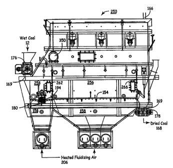
208. Vessel 152 is divided in two stages: a first stage 254 and second stage
256.
Although illustrated in Figs. 15-16 as a two-stage dryer, additional stages
may be added
and further processing can be achieved. Typically, wet sized coal 12 enters
the first stage
254 of the fluidized bed drier 250 through the freeboard region 162 at entry
point 164.
The wet sized coal 12 is preheated and partially dried (i.e., a portion of
surface moisture
is removed) by hot condenser cooling water 252 entering, circulating and
exiting through
the heating coils of in-bed heat exchanger 258 contained inside the first
stage 254 (direct
heat). The wet sized coal 12 is also heated and fluidized by hot fluidizing
air 206.
Fluidizing air 206 is forced by fan 200 through the distributor plate 154 of
the first stage
254 of the fluidized bed dryer 250 after being heated by waste process heat
212 in
external heat exchanger 210.
In the first stage 254, the hot fluidization air stream 206 is forced through
the wet
sized coal 12 supported by and above distributor plate 154 to dry the coal and
separate
the fluidizable particles and non-fluidizable particles contained within the
coal. Heavier
or denser, non-fluidizable particles segregate out within the bed and collect
at its bottom
on the distributor plate 154. These non-fluidizable particles ("undercut") are
then
discharged from the first stage 254 as Stream 1 (260). Fluidized bed dryers
are generally
designed to handle non-fluidized material up to four inches thick collecting
at the bottom
of the fluidized bed. The non-fluidized material may account for up to 25% of
the coal
input stream. This undercut stream 260 can be directed through another
beneficiation
process or simply be rejected. Movement of the segregated material along the
distributor
CA 02729429 2011-01-25
plate 154 to the discharge point for stream 260 is accomplished by an inclined
horizontal-directional distributor plate 154, as shown in Fig. 16. The first
stage 254
therefore separates the fluidizable and non-fluidizable material, pre-dries
and preheats the
wet sized coal 12, and provides uniform flow of the wet sized coal 12 to the
second stage
256 contained within the fluidized bed dryer 250. From the first stage 254,
the fluidized
coal 12 flows airborne over a first weir 262 to the second stage 256 of the
bed dryer 250.
In this second stage of the bed dryer 250, the fluidized coal 12 is further
heated and dried
to a desired outlet moisture level by direct heat, hot condenser cooling water
252
entering, circulating, and exiting the heating coils of the in-bed heat
exchanger 264
contained within the second stage 256 to radiate sensible heat therein. The
coal 12 is also
heated, dried, and fluidized by hot fluidizing air 206 forced by fan 200
through the
distributor plate 154 into the second stage 256 of the fluidized bed dryer 250
after being
heated by waste process heat 212 in external heat exchanger 210.
The dried coal stream is discharged airborne over a second weir 266 at the
discharge end 169 of the fluidized bed dryer 250, and elutriated fines 166 and
moist air
are discharged through the top of the dryer unit. This second stage 256 can
also be used
to further separate fly ash and other impurities from the coal 12. Segregated
material will
be removed from the second stage 256 via multiple extraction points 268 and
270 located
at the bottom of the bed 250 (or wherever else that is appropriate), as shown
in Fig. 16 as
Streams 2 (268) and 3 (270). The required number of extraction points may be
modified
depending upon the size and other properties of the wet sized coal 12,
including without
limitation, nature of the undesirable impurities, fluidization parameters, and
bed design.
The movement of the segregated material to the discharge point(s) 260, 268,
and 270 can
be accomplished by an inclined distributor plate 154 shown in Fig. 16, or by
existing
commercially available horizontal-directional distributor plates. Streams 1, 2
and 3 may
be either removed from the process and land-filled or further processed to
remove
undesirable impurities.
The fluidization air stream 206 is cooled and humidified as it flows through
the
coal bed 250 and wet sized coal 12 contained in both the first stage 254 and
second stage
256 of the fluidized bed 156. The quantity of moisture which can be removed
from the
coal 12 inside the dryer bed is limited by the drying capacity of the
fluidization air stream
21
CA 02729429 2011-01-25
206. Therefore, the heat inputted to the fluidized bed 156 by means of the
heating coils
of the in-bed heat exchangers 258 and 264 increases the drying capacity of
fluidizing air
stream 206, and reduces the quantity of drying air required to accomplish a
desired
degree of coal drying. With a sufficient in-bed heat transfer surface, drying
air stream 206
could be reduced to values corresponding to the minimum fluidization velocity
needed to
keep particulate suspended. This is typically in the 0.8 meters/second range,
but the rate
could be increased to run at a higher value, such as 1.4 meters/second, to
assure that the
process never drops below the minimum required velocity.
To achieve maximum drying efficiency, drying air stream 206 leaves fluidized
bed 156 at saturation condition (i.e., with 100 % relative humidity). To
prevent
condensation of moisture in the freeboard region 162 of the fluidized bed
dryer 250 and
further downstream, coal dryer 250 is designed for outlet relative humidity
less than
100%. Also, a portion of the hot fluidizing air 206 may be bypassed around the
fluidized
bed 156, and mixed with the saturated air in the freeboard region 162 to lower
its relative
humidity (e.g., sparging), as explained more fully herein. Alternatively,
reheat surfaces
may be added inside the freeboard region 162 of the fluidized bed dryer 250 or
heating of
vessel skin, or other techniques may be utilized to increase the temperature
and lower the
relative humidity of fluidization air 206 leaving the bed dryer 250, and
prevent
downstream condensation. The moisture removed in the dryer is directly
proportional to
the heat input contained in the fluidizing air and heat radiated by the in-bed
heat
exchangers. Higher heat inputs result in higher bed and exit temperatures,
which increase
the water transport capabilities of the air, thereby lowering the required air-
to-coal ratio
required to achieve the desired degree of drying. The power requirements for
drying are
dependent upon the air flow and the fan differential pressure. The ability to
add heat in
the dryer bed is dependant upon the temperature differential between the bed
and heating
water, the heat transfer coefficient, and the surface area of the heat
exchanger. In order to
use lower temperature waste heat, more heat transfer area is therefore needed
to introduce
the heat into the process. This typically means a deeper bed to provide the
necessary
volume for the heat coils of the in-bed heat exchangers. Thus, intended goals
may dictate
the precise dimensions and design configuration of the fluidized bed dryer of
the present
invention.
22
CA 02729429 2011-01-25
Coal streams going into and out of the dryer include the wet sized coal 12,
processed coal stream, elutriated fines stream 166, and the undercut streams
260, 268,
and 270. To deal with the non-fluidizable coal, the dryer 250 is equipped with
a screw
auger 194 contained within the trough region 190 of first-stage distributor
plate 180 in
association with a collection hopper and scrubber unit for collecting the
undercut coal
particles, as disclosed more fully herein.
Typical associated components of a dryer include, amongst others, coal
delivery
equipment, coal storage bunker, fluidized bed dryer, air delivery and heating
system, in-
bed heat exchanger(s), environmental controls (dust collector),
instrumentation, and a
control and data acquisition system. In one embodiment, screw augers are used
for
feeding moist coal into and extracting the dried coal product out of the
dryer. Vane
feeders can be used to control the feed rates and provide an air lock on the
coal streams
into and out of the dryer. Load cells on the coal bunker provide the flow rate
and total
coal input into the dryer. Instrumentation could include, without limitation,
thermocouples, pressure gauges, air humidity meters, flow meters and strain
gauges.
With respect to fluidized-bed dryers, the first stage accomplishes pre-heating
and
separation of non-fluidizable material. This can be designed as a high-
velocity, small
chamber to separate the coal. In the second stage, coal dries by evaporation
of coal
moisture due to the difference in the partial pressures between the water
vapor and coal.
In a preferred embodiment, most of the moisture is removed in the second
stage.
The heating coils 280 contained within the in-bed heat exchanges 258 and 264
of
fluidized-bed dryer 250 are shown more clearly in Figs. 17-18. Each heating
coil is of
carbon steel construction consisting of a two-pass, U-tube coil connection 282
with an
integral water box 284 connected thereto with a cover, inlet flange 286,
outlet flange 288,
and lifting lugs 290. These heating coil bundles are designed for 150 psig at
300 OF with
150# ANSI flanges for the water inlet 286 and outlet 288. The heating coil
tubes 280 are
oriented across the width of the first-stage 254 and second-stage 256 of the
dryer unit,
and support plates 292 with lifting lugs are interspaced along the length of
the heating
coil bundles to provide lateral support.
An embodiment of the first-stage heat exchanger 258 contains 50 heating coil
pipes (280) having a 1'/z-inch diameter with Sch 40 SA-214 carbon steel finned
pipe,'/2-
23
CA 02729429 2011-01-25
inch-high fins, and %2 -inch fin pitch x 16-garage solid helical-welded carbon
steel fins
with a 1-inch horizontal clearances and a 1'/2-inch diagonal clearance. The
second-stage
heat exchanger 264, meanwhile, can consist of one long set of tube bundles, or
multiple
sets of tube bundles in series, depending upon the length of the second stage
of the dryer.
The tubes of the second-stage heat exchanger 264 will generally consist of 1-
1'/2-inch OD
tubing x 10 BWG wall SA-214 carbon steel finned pipe, '/4-'/2-inch-high fins,
and '/2-'/4-
incg fin pitch x 16-gauge solid helical- welded carbon steel fins with 1-inch
horizontal
clearance and I %2-inch diagonal clearance. In an embodiment of this
invention, the
second-stage heating coil pipes contain 110-140 tubes running the length of
the second
stage. The combined surface area of the tube bundles for both the first-stage
and second-
stage heat exchangers 258 and 264 is approximately 8,483 ft2.
The heat source provided to the fluidized bed under the present invention may
be
primary heat. More preferably, the heat source should be a waste heat source
like hot
condenser cooling water, process waste heat, hot flue gas, or spent turbine
steam, which
may be used alone or in combination with another waste heat source(s) or
primary heat.
Such waste heat sources are typically available in many if not most industrial
plant
operations, and therefore may be used to operate the contaminant separation
process of
the present invention on a more commercially economical basis, instead of
being
discarded within the industrial plant operation. U.S. patent application
publication no.
2006/0075682A1 filed on April 15, 2005, which shares a common co-inventor and
owner with this application, describes more fully how to integrate such
primary or waste
heat sources into the fluidized bed apparatus.
It has been found surprisingly that the concentration of sulfur and mercury
contaminants contained within the undercut streams 260, 268, and 270 are
significantly
greater than that of wet coal feed stream 12. Likewise, the elutriated fines
stream 166
exiting the top of the fluidized-bed dryer is enhanced in the presence of
contaminants
like fly ash, sulfur, and mercury. By using the particle segregation method of
the present
invention, the mercury concentration of the coal product stream 168 can be
reduced by
approximately 27%, compared with the mercury concentration of the wet coal
feed
stream 12. Moreover, the sulfur concentration of the coal product stream 168
can be
reduced by approximately 46%, and the ash concentration can be reduced by 59%.
24
CA 02729429 2011-01-25
Stated differently, using the present invention, approximately 27-54% of the
mercury
appearing in the wet coal feed can be concentrated in the undercut and
elutriated fines
output streams, and therefore removed from the coal product stream that will
go to the
boiler furnace. For sulfur and ash, the corresponding values are 25-51% and 23-
43%,
respectively. By concentrating the contaminants within the undercut stream in
this
manner, and significantly reducing the presence of the contaminants in the
coal product
stream 168 going to the boiler furnace for combustion, there will be less
mercury, SO2
and ash contained within the resulting flue gas, and therefore less burden on
the scrubber
technology conventionally used within industrial plant operations to treat the
flue gas
stream before it is vented to the atmosphere. This can result in significant
operational
and capital equipment cost savings for a typical industrial plant operation.
The fluidized bed designs for this invention are intended to be custom
designed to
maximize use of waste heat streams available from a variety of power plant
processes
without exposing the coal to temperatures greater than 300 IF, preferably
between 200-
300 OF. Other feedstock or fuel temperature gradients and fluid flows will
vary,
depending upon the intended goal to be achieved, properties of the fuel or
feedstock and
other factors relevant to the desired result. Above 300 OF, typically closer
to 400 OF,
oxidation occurs and volatiles are driven out of the coal, thereby producing
another
stream containing undesirable constituents that need to be managed, and other
potential
problems for the plant operations.
The fluidized-bed dryers are able to handle higher-temperature waste heat
sources
by tempering the air input to the dryer to less than 300 OF and inputting this
heat into heat
exchanger coils within the bed. The multi-stage design of a fluidized-bed
dryer creates
temperature zones which can be used to achieve more efficient heat transfer by
counter
flowing of the heating medium. The coal outlet temperature from a dryer bed of
the
present invention is relatively low (typically less than 140 F) and produces
a product
which is relatively easy to store and handle. If a particular particulate
material requires a
lower or higher product temperature, the dryers can be designed to provide the
reduced or
increased temperature.
Elutriated particles 600 collected by particle-control equipment are typically
very
small in size and rich in fly ash, sulfur, and mercury. Figure 19 is a
schematic drawing
CA 02729429 2011-01-25
indicating a process for removing mercury through the use of activated steam
602 to
produce activated carbon 604. As shown in Figure 19, elutriated particle
stream 600 is
heated in a fluidized-bed heater or mild gasifier 606 to a temperature of 400
OF or higher
to evaporate the mercury. Fluidizing air 608, forced through the fluidized bed
608, drives
out the mercury into overhead stream 610. Evaporated mercury in overhead
stream 610
can be removed by existing commercially available mercury control techniques,
for
example, by activated carbon injected into the air stream, or the mercury-
laden air stream
610 may be passed though a bed of activated carbon 612 as illustrated in
Figure 19.
Since mercury concentration in the treatment stream 610 will be much higher
compared
to the flue gas 306 leaving the furnace 330, and the total volume of the air
stream that
needs to be treated is very small compared to the flue gas leaving the
furnace, this will
be a very efficient mercury removal process. A heat exchanger.614 through
which
cooling fluid 616 is circulated, may be used to cool hot mercury-free stream
618. Heat
can be harvested in the cooling process and used to preheat fluidization air
620 to the
fluidized bed heater or mild gasifier 606. The mercury-free fines 622 can be
burned in
the furnace 330 or, as illustrated in Figure 19, can be activated by steam 602
to produce
activated carbon 604. The produced activated carbon 604 can be used for
mercury control
at the coal-drying site or can be sold to other coal-burning power stations.
Figure 20 illustrates a process for gasifying elutriated fines 600. Elutriated
particle stream 600 is gasified in fluid bed gasifier 700 in combination with
fluidizing air
702. A gasifier is typically utilized at a higher temperature, such as 400 F,
where
combustible gases and volatiles are driven off. The product gas stream 704 is
combusted
in a combustion turbine 706 consisting of a combustion chamber 708, compressor
710,
gas turbine 712 and generator 714. The remaining char 716 in the fluidized-bed
gasifier
will be mercury-free, and can be burned in the existing furnace 330 or treated
by steam
718 to produce activated carbon 720.
The undercut streams can also be rich in sulfur and mercury. These streams can
be removed from the process and land-filled or further processed in a manner
similar to
the elutriated fines stream, to remove undesirable impurities.
In a preferred embodiment of the present invention, the undercut coal particle
stream 170 or 260 is conveyed directly to a scrubber assembly 600 for further
26
CA 02729429 2011-01-25
concentration of the contaminants by removal of fine coal particles trapped
therein. An
embodiment of the scrubber assembly 600 of the present invention is shown in a
cut-
away view in Figs. 21a and 21b. The scrubber assembly 600 is a box-like
enclosure
having side walls 602, an end wall 604, bottom 606, and top 608 (not shown),
and is
attached to the dryer 256 sidewall to encompass an undercut discharge port 610
through
which the screw auger 194 partially extends. It should be noted that any other
appropriate device that is capable of conveying the undercut coal particles in
a horizontal
manner could be substituted for the screw auger, including a belt, ram, or
drag chain.
The screw auger 194 will move the undercut particles lying near the bottom of
the
fluidized bed across the bed, through undercut discharge part 610, and into
scrubber
assembly 600 where they can accumulate separate and apart from the fluidized
dryer.
Distributor plate 620 is contained within the scrubber assembly 600. A
substream of hot
fluidizing air 206 passes upwardly through holes 622 in distributor plate 620
to fluidize
the undercut particle stream contained within the scrubber assembly. Of
course, the
undercut particles will reside near the bottom of the fluidized bed due to
their greater
specific gravity, but any elutriated fines trapped amongst these undercut
particles will rise
to the top of the fluidized bed, and be sucked back into the fluidized dryer
bed 250
through inlet hole 624 (the heat exchanger coils 280 are shown through this
hole in Fig.
22). In this manner, the undercut particles stream is further processed within
the scrubber
assembly of Fig. 21 to clean out the elutriated fines, thereby leaving an
undercut coal
particle stream that has a greater concentration of contaminants, and allowing
the fines
which are lower in contaminants to be returned to the fluidized bed for
further
processing.
When the undercut particles contained within the scrubber assembly have
accumulated to a sufficient degree, or are otherwise needed for another
purpose, gate 612
in end wall 604 may be opened to allow the accumulated undercut particles to
be
discharged through an outlet hole in the end wall wherein these undercut
particles are
pushed by the positive pressure of the imposed.by screw auger 294 on the
undercut
particles through them, or by other suitable mechanical conveyance means. Gate
612
could also be operated by a timer circuit so that it opens on a periodic
schedule to
discharge the accumulated undercut particles.
27
CA 02729429 2011-01-25
Yet another embodiment 630 of the scrubber assembly is shown in Figs. 22-24,
constituting two scrubber subassemblies 632 and 634 for handling larger
volumes of
undercut particles produced by the fluidized-bed dryer 250. As can be seen
more clearly
in Fig. 24, screw auger 194 extends through vestibule 636. Undercut coal
particles are
conveyed by screw auger 194 to this vestibule 636 and then into collection
chambers 638
and 640 which terminate in gates 642 and 644, respectively, or other
appropriate type of
flow control means.
As discussed above, distributor plates 654 and 656 may be included inside the
collection chambers 638 and 640 (see Fig. 26) so that a fluidizing airstream
passed
through holes 658 and 660 in the distributor plates fluidize the undercut
particles to
separate any elutriated fines trapped amongst the denser undercut particles.
Once gates
642 and 644 are opened, the elutriated fines will rise to the tops of chutes
646 and 648
through holes 660 and 662 for conveyance by suitable mechanical means back to
the
fluidized bed dryer 250. The undercut particles will drop through the bottom
of chutes
646 and 648, as previously described.
Once a predetermined volume of undercut particles have accumulated within the
collection chambers 638 and 640, or a predetermined amount of time has
elapsed, then
gates 642 and 644 are opened to permit the undercut particles to be discharged
into
chutes 646 and 648, respectively. The undercut particles will fall by means of
gravity
through outlet parts 650 and 652 in the bottom of chutes 646 and 648 into some
other
storage vessel or conveyance means for further use, further processing, or
disposal.
Gates 642 and 644 may be pivotably coupled to the collection chambers 638 and
640, although these gates may also be slidably disposed, upwardly pivoting,
downwardly
pivoting, laterally pivoting, or any other appropriate arrangement.
Additionally, multiple
gates may be operatively associated with a collection chamber to increase the
speed of
discharge of the undercut coal particles therefrom.
In an example embodiment, as illustrated in Fig. 25, gate 642 or 644 could
include a planar door portion 672 that covers discharge port 632 of collection
chanber
638, 640. Door portion 672 may have an area greater than an area of discharge
port 632.
Door portion 672 may comprise any rigid material such as steel, aluminum,
iron, and like
materials with similar physical characteristics. In an alternate embodiment,
gate 670 will
28
CA 02729429 2011-01-25
be repeatedly operated, it may be advantageous to use a thinner material,
which can
reduce its weight. In this embodiment, the door portion 672 may also include
bracing or
supports (not shown) to add additional support against any outwardly acting
pressure
from within collection chamber 638, 640.
Gate 670 also includes at least one seal portion 674 disposed on or to an
inner
surface of door portion 672 to form a generally positive seal over discharge
opening 632.
Seal portion 674 could have an area greater than an area of discharge opening
632. Seal
member 674 could comprise any resiliently compressible material such as
rubber, an
elastic plastic, or like devices having similar physical characteristics.
A cover 676 may be disposed on seal member 672 to protect or cover it from the
fluidized and non-fluidized material that will confronting seal gate 670. As
particularly
illustrated in Fig. 26, cover 676 comprises a sheet having an area that can be
less than an
area of discharge opening 632. When gate 670 is in its closed position cover
676 is
nested in discharge port 632. Cover 676 can comprise any rigid material such
as steel,
aluminum, iron, and like materials with similar physical characteristics.
However, other
materials may also be utilized for cover 676.
In an example embodiment, an actuation assembly 680 is operatively coupled to
gate 670 to move it from an open position and a closed position, whereby the
coal is
dischargeable from fluidizing collector 620 when gate 670 is in the open
position.
Actuation assembly 280 comprises a pneumatic piston rod 684 and cylinder 686
that are
in operative communication with a fluid pneumatic system (not shown). The
fluid
pneumatic system may include the utilization of fluid heat streams such as
waste heat
streams, primary heat streams, or a combination to the two.
Since fluidization will be occurring in the fluidizing collector 632,
construction
materials may be used that are able to withstand the pressures needed to
separate the fine
particulates from the denser and/or larger contaminated material. Such
construction
material can include steel, aluminum, iron, or an alloy having similar
physical
characteristics. However, other materials may also be used to manufacture the
fluidizing
collection chamber 638, 640.
The fluidizing collection chamber 638, 640 can also, although not necessary,
include an in-collector heater (not shown) that may be operatively coupled to
a fluid heat
29
CA 02729429 2011-01-25
stream to provide additional heat and drying of the coal. The in-collector
heater may be
fed by any fluid heat stream available in the power plant including primary
heat streams,
waste streams, and any combination there.
As illustrated in Figs. 23 and 24, the top wall 632a and 632b of fluidizing
collection chamber 638, 640 may traverse away from the fluidized bed at an
angle such
that the fluid heat stream entering the fluidizing collection chamber 638, 640
is directed
toward passage A or second passage B, as indicated by reference arrows A and
B, and
into the fluidized bed. An inner surface of the top wall 632 can include
impressions, or
configurations such as channels, indentations, ridges, or similar arrangements
that may
facilitate the flow of the fluidized particulate matter through passage A or
second passage
B and into the fluidized bed.
Referring to Figs. 22 and 27, a window assembly 650 may be disposed on the
peripheral wall. 651 to permit viewing of the fluidization occurring within
the interior of
the fluidizing collection chamber 638, 640. In an example embodiment of the
present
invention, the window assembly 650 comprises at least an inner window 652
comprising
a transparent and/or shatter resistant material such as plastic,
thermoplastic, and like
materials fastened to and extending across a window opening 654. A support or
plate
656 may be disposed to a perimeter outer surface of the inner window 652 to
provide
support against outwardly acting pressure against the inner window 652. The
support
656 may comprise any substantially rigid material such as steel, aluminum, or
like
material. A second or outer widow 658 may be disposed to an outer surface of
the
support 656 to provide additional support against outwardly acting pressures
within the
fluidizing collection chamber 638, 640. A bracket 660 and fastener 662 may be
utilized
to secure window assembly 650 into place. Bracket 660 may comprise an L-shape,
C-
shape, or similar shape that is capable of securing the window assembly 650.
Fastener
662 may comprise a bolt, screw, c-clamp, or any fastener known to one skilled
in the art.
Junction 300 comprises a bottom wall 302, a top wall 304 and a plurality of
side
walls 306 defining an interior 308. A distributor plate 310 is spaced a
distance from the
bottom wall 302 of junction 300 defining a plenum 312 for receiving at least
one fluid
heat stream that flows into the plenum 312 through at least one inlet 316.
Distributor
plate 312 of junction 300 is preferably sloped or angled toward fluidizing
collector 220 to
CA 02729429 2011-01-25
assist in the transport of non-fluidized material from the fluidized dryer bed
130. As the
non-fluidized material travels through junction 300, apertures 314 extending
through
distributor plate 310 to diffuse a fluid heat stream through the non-fluidized
material;
thereby causing the separation of fine particulate material. The fine
particulate material
becomes fluidized and flows back into the interior 106 of fluidized dryer bed
130. The
apertures 314 extending through distributor plate 310 of junction 300 may be
angled
during manufacturing to control a direction of the fluid heat stream.
Use of the undercut particles separated from the dryer 250 by the scrubber
assembly 600 will depend upon its composition. If these undercut particles
contain
acceptable levels of sulfur, ash, mercury, and other undesirable constituents,
then they
may be conveyed to the furnace boiler for combustion, since they contain
desirable heat
values. If the undesirable constituents contained within these undercut
particles are
unacceptably high, however, then the undercut particles may be further
processed to
remove some or all of the levels of these undesirable constituents, as
disclosed more
fully in U.S. Patent Application publication No. 2006/00756821A1 and U.S.
Patent No.
7,725,646, both of which were filed on April 15, 2005 and share a common co-
inventor
and co-owner with this application. Only if the levels of undesirable
constituents
contained within the undercut particles are so high that they cannot be viably
reduced
through further processing will the undercut particles be disposed of in a
landfill, since
this wastes the desirable heat values contained within the undercut particles.
Thus, the
scrubber assembly 600 of the present invention not only allows the undercut
coal
particles stream to be automatically removed from the fluidized bed to enhance
the
efficient and continuous operation of the dryer, but also permits these
undercut particles
to be further processed and productively used within the electricity
generation plant or
other industrial plant operation. The following examples illustrate the low-
temperature
coal dryer that forms a part of the present invention.
Example I - Effect of Moisture Reduction on the Coal Composition
PRB coal and lignite coal samples were subjected to chemical and moisture
analysis to determine their elemental and moisture composition. The results
are reported
in Table 1 below. As can be seen, the lignite sample of coal exhibited on
average 34.03%
31
CA 02729429 2011-01-25
wt carbon, 10.97% wt oxygen, 12.30% wt fly ash, 0.51% wt sulfur, and 38.50% wt
moisture. The PRB subbituminous coal sample meanwhile exhibited on average
49.22%
wt carbon, 10.91% wt oxygen, 5.28% wt fly ash, 0.35% wt sulfur, and 30.00%
moisture.
An "ultimate analysis" was conducted using the "as-received" values for these
lignite and PRB coal samples to calculate revised values for these elemental
composition
values, assuming 0% moisture and 0% ash ("moisture and ash-free"), and 20%
moisture
levels, which are also reported in Table 1. As can be seen in Table 1, the
chemical
compositions and moisture levels of the coal samples significantly change.
More
specifically for the 20% moisture case, the lignite and PRB coal samples
exhibit large
increases in carbon content to 44.27% wt and 56.25% wt, respectively, along
with
smaller increases in oxygen content to 14.27% wt and 12.47% wt, respectively.
The
sulfur and fly ash constituents increase slightly too (although not on an
absolute basis).
Just as importantly, the heat value (HHV) for the lignite coal increased from
6,406
BTU/lb to 8,333 BTU/lb, while the HHV value for the PBR coal increased from
8,348
BTU/lb to 9,541 BTU/lb.
Table 1
Units As-Received Moisture & Ash- 20% Fuel Moisture
Free
Lignite PRB Lignite PRB Lignite PRB
Carbon % wt 34.03 49.22 69.17 76.05 44.27 56.25
Hydrogen % wt 2.97 3.49 6.04 5.39 3.87 3.99
Sulfur % wt 0.51 0.35 1.04 0.54 0.67 0.40
Oxygen % wt 10.97 10.91 22.29 16.86 14.27 12.47
Nitrogen % wt 0.72 0.75 1.46 1.16 0.92 0.86
Moisture % wt 38.50 30.00 0.00 0.00 20.00 20.00
Ash % wt 12.30 5.28 0.00 0.00 16.00 6.30
TOTAL % wt 100.00 100.00 100.00 100.00 100.00 100.00
HHV BTU/Ib 6,406 8,348 13,021 12,899 8,333 9,541
H the1 BTU/1b -2,879 2,807 -1,664 -2,217
32
CA 02729429 2011-01-25
Example II - Pilot Dryer Coal Particle Segregation Results
During the Fall of 2003 and Summer of 2004, over 200 tons of lignite was dried
in a pilot fluidized bed coal dryer built by Great River Energy at Underwood,
North
Dakota. The dryer capacity was 2 tons/hr and was designed for determining the
economics of drying North Dakota lignite using low-temperature waste heat and
determining the effectiveness of concentrating impurities such as mercury, ash
and sulfur
using the gravimetric separation capabilities of a fluidized bed.
Coal streams in and out of the dryer included the raw coal feed, processed
coal
stream, elutriated fines stream and the undercut. During tests, coal samples
were taken
from these streams and analyzed for moisture, heating value, sulfur, ash and
mercury.
Some of the samples were sized and further analysis was done on various size
fractions.
The pilot coal dryer was instrumented to allow experimental determination of
drying rates under a variety of operating conditions. A data collection system
allowed
the recording of dryer instruments on a 1-minute bases. The installed
instrumentation
was sufficient to allow for mass and energy balance calculations on the
system.
The main components of the pilot dryer were the coal screen, coal delivery
equipment, storage bunker, fluidized bed dryer, air delivery and heating
system, in-bed
heat exchanger, environmental controls (dust collector), instrumentation, and
a control
and data acquisition systems (See Fig. 28). Screw augers were used for feeding
coal in
and products out of the dryer. Vane feeders are used to control feed rates and
provide air
lock on the coal streams in and out of the dryer. Load cells on the coal
burner provided
the flow rate and total coal input into the dryer. The undercut and dust
collector
elutriation were collected in totes which were weighted before and after the
test. The
output product stream was collected in a gravity trailer which was equipped
with a scale.
The coal feed system was designed to supply'/4-minus coal at up to 8000 lbs/hr
to the
dryer. The air system was designed to supply 6000 SCFM @ 40 inches of water.
An air
heating coil inputted 438,000 BTU/hr and the bed coil inputted about 250,000
BTUs/hr.
This was enough heat and air flow to remove about 655 lbs of water per hour.
. Typical tests involved filling the coal bunker with 18,000 lbs of 1/4" minus
coal.
The totes would be emptied and the gravity trailer scale reading recorded.
Coal samples
on the feed stock were collected either while filling the bunker or during the
testing at the
33
CA 02729429 2011-01-25
same time interval as the dust collector, undercut and gravity trailer samples
(normally
every 30 minutes after achieving steady state.) The dust collector and all
product augers
and air locks were then started. The supply air fan was started and set to
5000 scfm. The
coal feed to the dryer was then started and run at high speed to fill the
dryer. Once the
bed was established in the dryer, the air temperature was increased, heating
was lined up
to the bed coil, and the air flow adjusted to the desired value. The tests
were then run for
a period of 2-3 hours. One test was run for eight hours. After the test, the
totes were
weighed and the gravity trailer scale reading recorded. Instrument reading
from the test
was transferred to an excel spread sheet and the coal samples taken to the lab
for analysis.
The totes and gravity trailer were then emptied in preparation for the next
test.
During the Fall of 2003, 150 tons of lignite was sent through the single-stage
pilot
dryer with a distributor area of 23.5 ft .in 39 different tests. Coal was fed
into the
fluidized bed at rates between 3000 to 5000 lbs/hr. Air flows were varied from
4400 (3.1
ft/sec) to 5400 (3.8 ft/sec) scfm. The moisture reduction in the coal is a
function of the
feed rate and the heat input to the drier. The 1St pilot module had the
ability to remove
about 655 lb water per hour at the design water temperatures of 200 F.
Feeding coal at
83.3 lbs/min, one would expect a water removal rate of 0.13 lbs/lb coal.
During the Summer of 2004, the dryer was modified to two stages to improve
non-fluidized particle removal, and a larger bed coil was installed. After
modifying the
dryer module, the drying capability was increased to about 750,000 BTU/hr with
a water
removal rate of 1100 lbs/hr. An additional 50 tons of coal was dried in the
new module.
The modified module also allowed for the collection of an undercut stream off
the 1St
stage. The undercut was non-fluidized material which was removed from the
bottom of
the 1St stage. It was primarily made up of oversized and higher density
material that was
gravimetrically separated in the 1St stage. The total distributor plate area
was 22.5 fe.
Table 2 shows the coal quality for the dryer feed, elutriation, undercut and
product streams. The data indicates that the elutriation stream was high in
mercury and
ash, the undercut stream was high in mercury and sulfur, and the product
stream
experienced a significant improvement in heating value, mercury, ash, and #
SO2/mBTUs. The elutriation stream was primarily 40-mesh-minus and the undercut
stream was 8-mesh-plus.
34
CA 02729429 2011-01-25
Table 2: Coal Feed Quality Verses Product Streams Test 44
Coal Pounds Mercury Ash % HHV Sulfur % #S02/mbtu
ppb BTUs/lb
Feed 14902 91.20 18.05 5830.00 0.53 1.82
Undercut 2714 100.61 15.41 6877.00 0.76 2.20
Elutriation 789 136.58 30.26 5433.75 0.50 1.86
Product 7695 65.83 14.22 7175.25 0.55 1.54
Therefore, Test 44 reduced the mercury and sulfur in the coal product stream
by 40% and
15%, respectively.
Time variation of bed temperature, measured at six locations within the bed,
and
outlet air temperature are presented in Fig. 29. This information was used,
along with the
information on coal moisture content (obtained from coal samples) to close the
mass and
energy balance for the dryer and determine the amount or removed moisture from
coal.
Figure 30 shows the makeup of the undercut product for the 7 tests using the
modified pilot dryer. Test 41 had the best results with containing 48% of the
sulfur and
mercury and only 23% of the btu and 25% of the weight. Applying the results
from the
air jig test in Module 4 we could expect to remove 37% of 48% for the mercury
18%,
27% of 48% for the sulfur 13% and 7.1 of 23% for BTU loss 1.6%.
Example III - Some More Particle Segregation Results
Between September and December 2004, 115 tons of Canadian Lignite was dried
at the modified, two-stage pilot dryer located at Underwood, North Dakota.
Between 3
and 20 tons of material was run through the dryer during a daily test at flow
rates of
2000-7000 lbs/hr. This produced coal with moisture levels of 15-24% from a 31
%
moisture feed stock.
Load cells on the coal bunker provided the flow rate and total coal input into
the
dryer. The undercut and dust collector elutriation was collected into totes,
which were
weighed before and after each test. The output product stream was collected in
a gravity
trailer, which was equipped with a scale. The coal feed system was designed to
supply
CA 02729429 2011-01-25
'/4-minus coal particles at up to 8000 lbs/hr to the dryer. The air system was
designed to
supply 6000 SCFM at 40 inches of water. An air heating coil input of 438,000
BTU/hr
and a bed coil input of about 500,000 BTU/hr were applied to the dryer. This
was
enough heat and air flow to remove about 900 pounds of water per hour,
depending upon
ambient conditions and the temperature of the heating fluid.
The dryer output was typically 20% elutriation and undercut, and 80% product
at
7000 lbs/hr flow rates with their percentage increasing as the coal flow to
the dryer was
reduced. Samples were collected off each stream during the tests and compared
with the
input feed. The undercut ("UC") flow was typically set at 420-840 lbs/hr. As
the flow to
the dryer was reduced, this became a larger percentage of the output stream.
The
elutriation stream also tended to increase as a percentage of the output as
the coal flow
was reduced. This was attributed to longer residence time in the dryer and
higher
attrition with lower moisture levels.
Typical tests involved filling the coal bunker with 18,000 pounds of/4-inch-
minus coal. Lignite coal sourced from Canadian Mine No. 1 was first crushed to
2-inch-
minus. The material was then screened, placing the '/4-inch-minus material
(50%) in one
pile and the'/4-inch-plus material (50%) in another pile. The pilot dryer was
then filled
by adding alternating buckets from the two piles. The '/a-inch-plus material
was run
through a crusher prior to being fed up to the bunker, and the '/4-inch-minus
material was
fed in directly. Lignite coal sourced from Canadian Mine No. 2 was run
directly through
a crusher and into the pilot bunker without screening. Coal samples on the
feed stock
were collected from the respective stock piles. The dust collector ("DC"),
undercut
("UC"), and gravity trailer ("GT") samples were taken every 30 minutes after
achieving
steady state. When running the large amounts of the Mine No. 1 coal through
the dryer,
samples were taken daily with a grain probe on the gravity trailer, DC tote,
and UC tote.
The totes were emptied and the gravity scale reading recorded. The dust
collector
and all product augers and air locks were then started. The supply air fan was
started and
set to about 5000 SCFM. The coal feed to the dryer was then started and run at
high
speed to fill the dryer. Once the bed was established in the dryer, the air
temperature was
increased, heating water lined up to the bed coil, and the air flow adjusted
to the desired
value. The tests were then run for a period of 2-7 hours. The bed was not
always
36
CA 02729429 2011-01-25
emptied between tests and the nominal 3000 pounds of material accounted for in
the
results.
Tables 4-5 tabulate the results of the Canadian Lignite tests. Table 4
contains the
dryer input, sum or the output streams, actual and calculated, based upon the
change in
total moisture and the input. Table 5 contains data on the three output
streams for the
Mine No. 1 Coal Tests.
Table 4: Test Summary
Test Dryer Actual Calculated Percent
Input Dryer Dryer Difference
(lbs) Output Output (lbs)
(lbs)
Test 49 on Mine No. 2 6829 6088 6176 1.5
Coal
Test 50 on Mine No. 2 6871 5840 5522 -5.4
Coal
Test 52 on Mine No. 1 108,517 95,474 95,474 0
Coal
Test 57 on Mine No. 1 38,500 33,206 32,931 -0.8
Coal
Test 58 on Mine No. 1 7927 6396 6478 1.3
Coal
Test 59 on on Mine 27,960 25,320 25,278 -0.2
No. 1 Coal
Table 5: Mine No.1 Coal Tests 52, 57, and 59 Results
Output Tot. BTU % % % % %
Moisture Output BTU Sulfur Mercury Ash
52DC 19.53 7117 10.1 9.26 8.54 14.24 14.21
52UC 20.3 7280 6.9 6.48 16.83 12.97 9.36
37
CA 02729429 2011-01-25
52GT 21.93 7869 83.02 84.26 74.63 72.79 76.43
57DC 20.1 6019 8.62 7.11 5.69 10.0 11.81
57UC 16.4 5321 10.85 7.90 41.52 44.23 20.78
57GT 19.65 7711 80.53 84.99 52.79 45.76 67.4
58DC 18.43 6721 7.60 6.54 5.35 8.70 9.63
58UC 12.40 6375 18.96 15.48 45.38 44.03 33.49
58GT 16.09 8294 73.44 77.98 49.28 47.27 56.88
59DC 23.24 6324 11.49 9.46 11.65 N/A 22.54
59UC 30.14 6850 15.05 13.41 13.43 N/A 15.66
59GT 22.42 8069 73.46 77.13 74.92 N/A 61.8
Tests 52, 57, 58, and 59 were conducted on the Mine No. 1 coal. Test 58 was a
controlled test, and for Tests 52, 57, and 59 the bunker was being filled with
coal during
the dryer operation.
Test 52 was conducted for the purpose of removing about 25% of the water in
the
coal, and then bagging it for shipment to GTI for further testing. During this
type of
testing, we were filling the bunker at the same time material was being fed
into the dryer,
thereby making it difficult to track the input. For this test, the input was
estimated by
correcting the total output back to the coal feed total moisture. Test 52 was
conducted on
six separate days over a three-week period. After the second day of the test,
the bed was
not dumped, and the coal remained in the dryer for two-plus days in a fairly
dry
condition. This coal started smoldering in the UC tote and in the dryer bed.
When the
dryer was started, ignition took place, and several of the explosion panels
needed to be
replaced. The very dry condition of the coal and the period of time it sat, as
well as the
temperature of the bed when the unit was shut down contributed to this
problem. We
discontinued leaving coal in the dryer bed without proper cool down, and for
not longer
than one day. This seemed to eliminate the problem.
Tests 57, 58, and 59 were all one-day tests. During Tests 57 and 59, coal was
added to the bunker during dryer operation, and we needed to estimate the coal
feed.
Test 57 was conducted at a coal inlet flow rate of about 7000 lbs/hr. Tests 58
and 59
were conducted at an inlet coal flow of about 5000 lbs/hr. The cooler
temperature of
38
CA 02729429 2011-01-25
early December had reduced the dryer's capacity. The mercury analyzer
malfunctioned
during Test 59.
The results of Table 5 provide good evidence that the UC stream is capable of
removing a significant amount of the sulfur and mercury from the coal feed
stream, while
retaining the heat value of the coal feed stream.
The above specification, drawings, and examples provide a complete description
of the structure and operation of the particulate material separator of the
present
invention. However, the invention is capable of use in various other
combinations,
modifications, embodiments, and environments without departing from the spirit
and
scope of the invention. Therefore, the description is not intended to limit
the invention to
the particular form disclosed.
39