Note: Descriptions are shown in the official language in which they were submitted.
CA 02729474 2010-12-24
WO 2010/003557 PCT/EP2009/004603
Apparatus and Method for Generating a Bandwidth Extended Signal
Description
Embodiments according to the invention relate to audio signal processing and,
in
particular, to an apparatus and a method for generating a bandwidth extended
signal from
an input signal, an apparatus and a method for providing a bandwidth reduced
signal based
on an input signal and an audio signal.
Perceptually adapted coding of audio signals, providing a substantial data
rate reduction
for efficient storage and transmission of these signals, has gained wide
acceptance in many
fields. Many coding algorithms are known, e.g,, MPEG 1/2 Layer 3 ("MP3") or
MPEG 4
AAC (Advanced Audio Coding). However, the coding used for this, in particular
when
operating at lowest bit rates, can lead to an reduction of subjective audio
quality which is
often mainly caused by an encoder side induced limitation of the audio signal
bandwidth to
be transmitted.
It is known from WO 98 57436 to subject the audio signal to a band limiting in
such a
situation on the encoder side and to encode only a lower band of the audio
signal by means
of a high quality audio encoder ("core coder"). The upper band, however, is
only very
coarsely characterized, i.e. by a set of parameters which reproduces the
spectral envelope
of the upper band. On the decoder side, the upper band is then synthesized.
For this
purpose, a harmonic transposition is proposed wherein the lower band of the
decoded
audio signal is supplied to a filterbank. Filterbank channels of the lower
band are
connected to filterbank channels of the upper band, or are "patched", and each
patched
bandpass signal is subjected to an envelope adjustment. The synthesis
filterbank belonging
to a special analysis filterbank receives bandpass signals of the audio signal
in the lower
band and envelope-adjusted bandpass signals of the lower band which are
harmonically
patched into the upper band. The output signal of the synthesis filterbank is
an audio signal
extended with regard to its original bandwidth which is transmitted from the
encoder side
to the decoder side by the core coder operating a very low data rate. In
particular,
filterbank calculations and patching in the filterbank domain may become a
high
computational effort.
Complexity-reduced methods for a bandwidth extension of band-limited audio
signals
instead use a copying function of low-frequency signal portions (LF) into the
high
frequency range (HF) in order to approximate information missing due to the
band
limitation. Such methods are described in M. Dietz, L. Liljeryd, K. Kjorling
and 0. Kunz,
CA 02729474 2010-12-24
wo 2010/003557 2 PCT/EP2009/004603
"Spectral Band Replication, a novel approach in audio coding," in 112th AES
Convention,
Munich, May 2002; S. Meltzer, R. Bohm and F. Henn, "SBR enhanced audio codecs
for
digital broadcasting such as "Digital Radio Mondiale" (DRM)," 112th AES
Convention,
Munich, May 2002; T. Ziegler, A. Ehret, P. Ekstrand and M. Lutzky, "Enhancing
mp3
with SBR: Features and Capabilities of the new mp3PRO Algorithm," in 112th AES
Convention, Munich, May 2002; International Standard ISO/IEC 14496-
3:2001/FPDAM
1, "Bandwidth Extension," ISO/IEC, 2002, or "Speech bandwidth extension method
and
apparatus", Vasu Iyengar et al. US Patent Nr. 5,455,888.
In these methods, no harmonic transposition is performed, but successive
bandpass signals
of the lower band are introduced into successive filterbank channels of the
upper band. By
this, a coarse approximation of the upper band of the audio signal is
achieved. In a further
step, this coarse approximation of the signal is then assimilated with respect
to the original
by a post processing using control information gained from the original
signal. Here, e.g.
scale factors serve for adapting the spectral envelope, an inverse filtering,
and the addition
of a noise floor for adapting tonality and a supplementation of sinusoidal
signal portions
for missing harmonics, as it is also described in the MPEG-4 High Efficiency
Advanced
Audio Coding (HE-AAC) standard.
Apart from this, further methods are using a phase vocoder for bandwidth
extension. When
applying the phase vocoder for spectral spreading, frequency lines move
further apart from
each other. If gaps exist in the spectrum, e.g. by quantization, the same are
even increased
by the spreading. In an energy adaption, remaining lines in the spectrum
receive too much
energy compared to the respective lines in the original signal.
Fig. 13 shows a schematic illustration of a bandwidth extension 1300 using a
phase
vocoder. In this example, two patches 1312, 1314 are added to a low frequency
band 1302
of a signal. The upper cut-off frequency 1320 of the signal, also called Xover
frequency
(crossover frequency) is the low-end frequency of the neighboring patch 1312
and the
double of the x-over frequency is the upper cut-off frequency of the
neighboring patch
1312 and the lower cut-off frequency of the next patch 1314. The phase vocoder
doubles
the frequency of the frequency lines of the low frequency band 1302 of the
signal to obtain
the neighboring patch 1312 and triples the frequencies of the frequency lines
of the low
frequency band 1302 of the signal to obtain the next patch 1314. Therefore, a
spectral
density of the neighboring patch 1312 is only half of a spectral density of
the low
frequency band 1302 of the signal and the spectral density of the next patch
1314 is only
one third of the spectral density of the low frequency band 1302 of the
signal.
=
CA 02729474 2013-08-16
3
By the concentration of the energy in bands (patches) to only few frequency
lines, a substantial change
in timbre results which differs from the original. The energy of formerly more
bands (frequency lines)
is summed up to the fewer remaining ones.
Some examples for phase vocoders and their applications are presented in
"Frederik Nagel and Sascha
Disch, A Harmonic Bandwidth Extension Method for Audio Codecs," ICASSP'09 and
"M. Puckette.
Phase-locked Vocoder. IEEE ASSP Conference on Applications of Signal
Processing to Audio and
Acoustics, Mohonk 1995.", Robel, A.:
Transient detection and preservation in the phase vocoder;
citeseer.ist.psu.edu/679246.html",
"Laroche L., Dolson M.: Improved phase vocoder timescale modification of
audio", IEEE Trans.
Speech and Audio Processing, Vol. 7, No. 3, pp. 323-332" and United States
Patent 6549884.
One approach for filling the gaps is shown in WO 00/45379. It contains a
method and an apparatus for
enhancement of source coding systems utilizing high frequency reconstruction.
The application
addresses the problem of insufficient noise contents in a reconstructed
highband by adaptive noise-floor
addition. Adding noise may fill the gaps, but the audio quality or subjective
quality may not be
increased sufficiently.
It is the object of the present invention to provide a concept for a bandwidth
extension of audio signals
which increases the subjective quality of bandwidth extended signals.
An embodiment of the invention provides an apparatus for generating a
bandwidth extended signal
from an input signal. The input signal is represented, for a first band by a
first resolution data and for a
second band by a second resolution data, the second resolution being lower
than the first resolution.
The apparatus comprises a patch generator and a combiner. The patch generator
is configured to
generate a first patch from the first band of the input signal according to a
first patching algorithm and
configured to generate a second patch from the first band of the input signal
according to a second
patching algorithm. A spectral density of the second patch generated according
to the second patching
algorithm is higher than a spectral density of the first patch generated
according to the first patching
algorithm. The combiner is configured to combine the first patch, the second
patch and the first band of
the input signal to obtain the bandwidth extended signal. The apparatus for
generating a bandwidth
extended signal is configured to scale the input signal according to the first
patching algorithm and
according to the second patching
CA 02729474 2010-12-24
4
wo 2010/003557 PCT/EP2009/004603
algorithm or to scale the first patch and the second patch, so that the
bandwidth extended
signal fulfils a spectral envelope criterion.
Embodiments according to the present invention are based on the central idea
that a patch
with low spectral density (which means, for example, the patch comprises gaps
in
comparison to a low frequency band of the input signal) is combined with a
patch with
high spectral density (which means, for example, the patch comprises only few
gaps or no
gaps in comparison with the low frequency band of the input signal) for
extending the
bandwidth of an input signal. Since both patches are generated based on the
input signal,
the high frequency bandwidth extension of the low frequency band of the input
signal may
provide a good approximation of the original audio signal. Additionally, the
first and the
second patch may be scaled before (by scaling the input signal) or after
generation to fulfill
a spectral envelope criterion, since the spectral envelope of the original
audio signal should
be considered for the reconstruction of the high frequency band of the input
signal. In this
way, the subjective quality or the audio quality of the bandwidth extended
signal may be
significantly increased.
In some embodiments according to the invention, the first patching algorithm
is a harmonic
patching algorithm. In other words, the first patch is generated so that only
frequencies that
are integer multiples of frequencies of the first band of the input signal are
contained by the
first patch. In addition, the second patching algorithm may be a mixing
patching algorithm.
This means, for example, that the second patch may be generated, so that the
second patch
contains frequencies that are integer multiples of frequencies of the first
band of the input
signal and frequencies that are not integer multiples of frequencies of the
first band of the
input signal. Therefore, the spectral density of the second patch is higher
than the spectral
density of the first patch. By combining the first patch and the second patch,
missing
frequency lines of the first patch may be filled by frequency lines of the
second patch. In
this way, the gaps of the harmonic bandwidth extension according to the first
patching
algorithm may be filled by the second patch and the audio quality of the
bandwidth
extended signal may be significantly improved.
Some embodiments according to the invention relate to an apparatus for
providing a
bandwidth reduced signal based on an input signal. The apparatus comprises a
spectral
envelope data determiner, a patch scaling control data generator, and an
output interface.
The spectral envelope data determiner is configured to determine spectral
envelope data
based on the high frequency band of the input signal. The patch scaling
control data
generator is configured to generate patch scaling control data for scaling the
bandwidth
reduced signal at the decoder or for scaling a first patch and a second patch
by the decoder,
CA 02729474 2010-12-24
wo 2010/003557 PCT/EP2009/004603
so that a bandwidth extended signal generated by the decoder fulfills a
spectral envelope
criterion. The spectral envelope criterion is based on the spectral envelope
data. The first
patch is generated from a low frequency band of the bandwidth reduced signal
according to
a first patch algorithm and the second patch is generated from the low
frequency band of
5 the bandwidth reduced signal according to a second patching algorithm. A
spectral density
of the second patch generated according to the second patching algorithm is
higher than a
spectral density of the first patch generated according to the first patching
algorithm. The
output interface is configured to combine a low frequency band of the input
signal, the
spectral envelope data, and the power scaling control data to obtain the
bandwidth reduced
signal. Further, the output interface is configured to provide the bandwidth
reduced signal
for transmission or storage.
Some further embodiments according to the invention relate to an audio signal
comprising
a first band and a second band. The first band is represented by a first
resolution data and
the second band is represented by a second resolution data. The second
resolution is lower
than the first resolution. The second resolution data is based on spectral
envelope data of
the second band and patch-scaling control data of the second band for scaling
the audio
signal at a decoder or for scaling a first patch and a second patch by the
decoder, so that a
bandwidth extended signal generated by the decoder fulfills a spectral
envelope criterion.
The spectral envelope criterion is based on the spectral envelope data. The
first patch is
generated from the first band of the audio signal according to a first
patching algorithm and
the second patch is generated from the first band of the audio signal
according to a second
patching algorithm. A spectral density of the second patch generated according
to the
second patching algorithm is higher than a spectral density of the first patch
generator
according to the first patching algorithm.
Embodiments according to the invention will be detailed subsequently referring
to the
appended drawings, in which:
Fig. 1 is a block diagram of an apparatus for generating a bandwidth
extended
signal from an input signal;
Fig. 2a is a schematic illustration of a generated first patch;
Fig. 2b is a schematic illustration of a generated first and second patch;
Fig. 3a is a block diagram of an apparatus for generating a bandwidth
extended
signal from an input signal;
CA 02729474 2010-12-24
wo 2010/003557 6 PCT/EP2009/004603
Fig. 3b is a schematic illustration of a clipped sinusoidal input
signal;
Fig. 3c is a schematic illustration of a half wave rectified
sinusoidal input signal;
Fig. 3d is a schematic illustration of a clipped and full wave
rectified sinusoidal
input signal;
Fig. 4 is a block diagram of an apparatus for generating a bandwidth
extended
signal from an input signal;
Fig. 5a is a schematic illustration of a filterbank implementation of
a phase vocoder;
Fig. 5b is a detailed illustration of a filter of Fig. 5a;
Fig. 5c is a schematic illustration for the manipulation of the
magnitude signal and
the frequency signal in a filter channel of Fig. 5a;
Fig. 6 is a schematic illustration of a transformation implementation
of a phase
vocoder;
Fig. 7 is a block diagram of an apparatus for generating a bandwidth
extended
signal from an input signal;
Fig. 8 is a block diagram of an apparatus for generating a bandwidth
extended
signal from an input signal;
Fig. 9 is a block diagram of an apparatus for generating a bandwidth
extended
signal from an input signal;
Fig. 10 is a block diagram of an apparatus for providing a bandwidth
reduced signal
based on an input signal;
Fig. 11 is a flow chart of a method for generating a bandwidth
extended signal from
an input signal;
Fig. 12 is a flow chart of a method for providing a bandwidth reduced
signal based
on an input signal; and
CA 02729474 2010-12-24
7
wo 2010/003557 PCT/EP2009/004603
Fig. 13 is a schematic illustration of a known bandwidth extension
algorithm.
In the following, the same reference numerals are partly used for objects and
functional
units having the same or similar functional properties and the description
thereof with
regard to a figure shall apply also to other figures in order to reduce
redundancy in the
description of the embodiments.
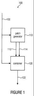
Fig. 1 shows a block diagram of an apparatus 100 for generating a bandwidth
extended
signal 122 for an input signal 102 according to an embodiment of the
invention. The input
signal 102 is represented, for a first band by a first resolution data, and
for a second band
by a second resolution data, the second resolution being lower than the first
resolution. The
apparatus 100 comprises a patch generator 110 connected to a combiner 120. The
patch
generator 120 generates a first patch 112 from the first band of the input
signal 102
according to a first patching algorithm and generates a second patch 114 from
the first
band of the input signal 102 according to a second patching algorithm. A
spectral density
of the second patch 114 generated according to the second patching algorithm
is higher
than a spectral density of the first patch 112 generated according to the
first patching
algorithm. The combiner 120 combines the first patch 112, the second patch 114
and the
first band of the input signal 102 to obtain the bandwidth extended signal
122. Further, the
apparatus 100 for generating a bandwidth extended signal 122 scales the input
signal 102
according to the first patching algorithm and according to the second patching
algorithm or
scales the first patch 112 and the second patch 114 so that the bandwidth
extended signal
122 fulfills a spectral envelope criterion.
Spectral density means, for example, the density of different frequencies or
frequency lines
within a frequency band. For example, a frequency band reaching from 0Hz to
10kHz
comprising frequency portions with frequencies of 4k1-Iz and 81cHz has a lower
spectral
density than the same frequency band comprising frequency portions with
frequencies of
2kHz, 4kHz, 6IcHz, 8kHz and 10kHz. Since the spectral density of the first
patch 112 is
lower than the spectral density of the second patch 114, the first patch 112
comprises gaps
in comparison with the second patch 114. Therefore, the second patch 114 may
be used to
fill these gaps. Since both patches are based on the first band of the input
signal 102, both
patches are related to the characteristic of the original signal corresponding
to the input
signal 102. Therefore, the bandwidth extended signal 122 may be a good
approximation of
the original signal and the subjective quality or the audio quality of the
bandwidth
extension signal 122 may be significantly improved by using the described
concept. In this
CA 02729474 2010-12-24
wo 2010/003557 8 PCT/EP2009/004603
way, more energy may be distributed between the remaining lines and, for
example, a
unnatural sound may be avoided.
For example, the first patching algorithm may be a harmonic patching
algorithm.
Therefore, the patch generator 110 may generate the first patch 112 comprising
only
frequencies that are integer multiples of frequencies of the first band of the
input signal
102. A harmonic bandwidth extension may provide a good approximation of the
tonal
structure of the original signal, but this patching algorithm will leave gaps
between the
harmonic frequencies. These gaps may be filled by the second patch. For
example, the
second patching algorithm may be a mixing patching algorithm, which means that
the
patch generator 110 may generate the second patch 114 comprising integer
multiples of
frequencies of the first band of the input signal 102 (harmonic frequencies)
and frequencies
that are not integer multiples of the frequencies of the first band of the
input signal 102
(non-harmonic frequencies). The non-harmonic frequencies may be used for
filling the
gaps of the first patch 112. It may also be possible to combine the whole
second patch 114
(including the harmonic frequencies) with the first patch 112. In this
example, an
amplification of the harmonic frequencies due to the combination of the
harmonic
frequency portions of the first patch 112 and the second patch 114 may be
taken into
account by appropriately scaling the first patch 112 and/or the second patch
114.
The first patch 112 and the second patch 114 comprise at least partly the same
frequency
range. For example, the first patch 112 comprises a frequency band reaching
from 4kHz to
81cHz and the second patch 114 comprises a frequency band from 6k1-Iz to
10kHz. In some
embodiments according to the invention, a lower cut of frequency of the first
patch is equal
to a lower cut of frequency of the second patch and an upper cut of frequency
of the first
patch 112 is equal to an upper cut of frequency of the second patch 114. For
example, both
patches comprise a frequency band reaching from 4kHz to 8kHz.
Figs. 2a and 2b show an example for a first patch 112 according to a first
patching
algorithm 212 and a second patch 114 according to a second patching algorithm
214. For
better illustration, Fig. 2a shows only the first patches 112 and Fig. 2b
shows the first
patches 112 and the corresponding second patches 114. Fig. 2a illustrates an
example 200
for the first band 202 of the input signal 102 and two first patches 112
generated according
to the first patching algorithm 212. In this example, a patch comprises the
same bandwidth
as the first band 202 of the input signal 102. The bandwidth may also be
different. The
upper cut-off frequency 220 of the first band 202 of the input signal 102 is
denoted `Xover'
frequency (crossover frequency). In the example shown in Fig. 2a, patches
start at a
frequency equal to a multiple of the crossover frequency Xover 220. The
frequency lines
CA 02729474 2010-12-24
9
wo 2010/003557 PCT/EP2009/004603
within the first patches 112 are integer multiples of the frequency lines of
the first band
202 of the input signal 102 and may, for example, be generated by a phase
vocoder. These
first patches 112 comprise gaps in terms of missing frequency lines in
comparison to the
first band 202 of the input signal 102.
Fig. 2b additionally shows an example 250 for the two corresponding second
patches 114.
These patches are generated according to the second patching algorithm 214 and
comprise
harmonic and non-harmonic frequencies. The non-harmonic frequency lines may be
used
to fill the gaps of the first patches 112. The frequency lines of the second
patches 114 may
be generated, for example, by a non-linear distortion.
In this way, the gaps may not be filled arbitrarily as, for example, by
filling the gaps with
noise. The gaps are filled based on the first resolution data of the first
band of the input
signal and, therefore, based on the original signal.
The first band of the input signal 102 may represent, for example, the low
frequency band
of an original audio signal encoded with high resolution. The second band of
the input
signal 102 may represent, for example, a high frequency band of the original
audio signal
and may be quantized by one or more parameters as, for example, spectral
envelope data,
noise data and/or missing harmonic data with low resolution. An original audio
signal may
be, for example, an audio signal recorded by a microphone before processing or
encoding.
Scaling the input signal according to the first patching algorithm and
according to the
second patching algorithm means, for example, that the input signal is scaled
once
according to the first patching algorithm before the first patch is generated
and then the
first patch is generated based on the scaled input signal, and that the input
signal is scaled
once according to the second patching algorithm before the second patch is
generated and
then the second patch is generated based on the scaled input signal, so that
after the _
combination of the first patch, the second patch and the first band of the
input signal, the
bandwidth extended signal fulfills a spectral envelope criterion.
Alternatively, the first
patch and the second patch are scaled after their generation, so that the
bandwidth extended
signal also fulfills a spectral envelope criterion. Also a scaling of the
input signal according
to the first patching algorithm and according to the second patching algorithm
in
combination with a scaling of the first patch and the second patch may be
possible.
The combiner 120 may be, for example, an adder and the bandwidth extended
signal 122
may be a weighted sum of the first patch 112, the second patch 114 and the
first band of
the input signal 102.
CA 02729474 2010-12-24
WO 2010/003557 PCT/EP2009/004603
Fulfilling a spectral envelope criterion means, for example, that a spectral
envelope of the
bandwidth extended signal is based on a spectral envelope data contained by
the input
signal. The spectral envelope data may be generated by an encoder and may
represent the
5 second band of an original signal. In this way, the spectral envelope of
the bandwidth
extended signal may be a good approximation of the spectral envelope of the
original
signal.
The apparatus 100 may also comprise a core decoder for decoding the first band
of the
10 input signal 102.
The patch generator 110 and the combiner 120 may be, or example, specially
designed
hardware or part of a processor or micro controller or may be a computer
program
configured to run on a computer or a micro controller. The apparatus 100 may
be part of a
decoder or an audio decoder.
Fig. 3a shows a block diagram of an apparatus 300 for generating a bandwidth
extended
signal 122 from an input signal 102 according to an embodiment of the
invention. In this
example, the patch generator 110 comprises a phase vocoder 310 for generating
the first
patch and an amplitude clipper 320 for generating the second patch 114. The
phase
vocoder 310 and the amplitude clipper 320 are connected to the combiner 120.
The phase
vocoder 310 may spread the first band of the input audio signal 102 to
generate the first
patch 112 comprising harmonic frequencies. In a non-linear processing step,
the amplitude
clipper 320 may clip the input signal 102 to generate the second patch 114
comprising
harmonic and non-harmonic frequencies. Alternatively to the amplitude clipper
320, also a
half-wave rectifier, a full-wave rectifier, a mixer or a diode used in the
quadratic region of
the characteristic curve may be used to generate non-harmonic frequencies
based on the
input signal 102 by a non-linear processing step.
Figs. 3b, 3c and 3d show examples for clipped and/or rectified input signals
102 to
generate non-harmonic frequencies. Fig. 3b shows a schematic illustration 350
of a clipped
sinusoidal input signal 102. By clipping the signal, points of discontinuity
in the form of
abrupt changes of the signal slope 380 are caused and harmonic and non-
harmonic portions
with higher frequencies are generated.
Alternatively, Fig. 3c shows a schematic illustration 360 of a half-wave
rectified sinusoidal
input signal 102, also causing points of discontinuity 380.
CA 02729474 2010-12-24
11
WO 2010/003557 PCT/EP2009/004603
Further, a combination of clipping and rectifying may be possible. Fig. 3d
shows a
schematic illustration 370 of a clipped and full-wave rectified sinusoidal
input signal 102
causing different points of discontinuity 380.
By clipping and/or rectifying or applying other methods of nonlinear
processing generating
points of discontinuity 380, a wide spectrum of different frequencies may be
generated.
Therefore, a patch generated according to such a patching algorithm may
comprise a high
spectral density.
Fig. 4 shows a block diagram of an apparatus 400 for generating a bandwidth
extended
signal 122 from an input signal 102 according to an embodiment of the
invention. The
apparatus 400 is similar to the apparatus shown in Fig. 3a, but additionally
comprises a
spectral line selector 410. The phase vocoder 310 and the amplitude clipper
320 are
connected to the spectral line selector 410 and the spectral line selector 410
is connected to
the combiner 120. The spectral line selector 410 may select a plurality of
frequency lines
of the second patch 114 to obtain a modified second patch 414 that may be
complementary
to the first patch. A frequency line of the second patch 114 may be selected
if a
corresponding frequency line of the first patch 112 is missing. In other
words, the spectral
line selector 410 selects frequency lines of the second patch 114 for filling
gaps of the first
patch 112 and may disregard frequencies of the second patch 114 already
contained by the
first patch 112. In this way, the modified second patch 414 may comprise gaps
at
frequencies already contained by the first patch 112.
In this example, the combiner 120 combines the first patch 112, the modified
second patch
414 and the first band of the input signal 102.
The spectral line selector 410 may be, for example, part of the patch
generator 110 (as
shown in Fig. 4) or a separate unit.
In the following, with reference to Figs 5 and 6, possible implementations for
a phase
vocoder 310 are illustrated according to the present invention. Fig. 5a shows
a filterbank
implementation of a phase vocoder, wherein an audio signal is fed to an input
500 and
obtained at an output 510. In particular, each channel of the schematic
filterbank
illustrated in Fig. 5a includes a bandpass filter 501 and a downstream
oscillator 502.
Output signals of all oscillators from every channel are combined by a
combiner, which is,
for example, implemented as an adder and indicated at 503 in order to obtain
the output
signal. Each filter 501 is implemented such that it provides an amplitude
signal on the one
hand and a frequency signal on the other hand. The amplitude signal and the
frequency
CA 02729474 2010-12-24
wo 2010/003557 12 PCT/EP2009/004603
signal are time signals illustrating a development of the amplitude in a
filter 501 over
time, while the frequency signal represents a development of the frequency of
the signal
filtered by a filter 501.
A schematical setup of filter 501 is illustrated in Fig. 5b. Each filter 501
of Fig. 5a may be
set up as in Fig. 5b, wherein, however, only the frequencies fi supplied to
the two input
mixers 551 and the adder 552 are different from channel to channel. The mixer
output
signals of the mixers 551 are both lowpass filtered by lowpasses 553, wherein
the lowpass
signals are different insofar as they were generated by local oscillator
frequencies (LO
frequencies), which are out of phase by 900. The upper lowpass filter 553
provides a
quadrature signal 554, while the lower filter 553 provides an in-phase signal
555. These
two signals, i.e. Q, and I are supplied to a coordinate transformer 556 which
generates a
magnitude phase representation from the rectangular representation. The
magnitude signal
or amplitude signal, respectively, of Fig. 5a over time is output at an output
557. The
phase signal is supplied to a phase unwrapper 558. At the output of the
element 558, there
is no phase value present any more, which is always between 0 and 360 , but a
phase
value, which increases linearly. This "unwrapped" phase value is supplied to a
phase/frequency converter 559 which may, for example, be implemented as a
simple
phase difference calculator, which subtracts a phase of a previous point in
time from a
phase at a current point in time to obtain a frequency value for the current
point in time or
any other means for obtaining an approximation of a phase derivative. This
frequency
value is added to the constant frequency value fi of the filter channel i to
obtain a
temporarily varying frequency value at the output 560. The frequency value at
the output
560 has a direct component = fi and an alternating component = the frequency
deviation
by which a current frequency of the signal in the filter channel deviates from
the average
frequency
Thus, as illustrated in Figs. 5a and 5b, the phase vocoder achieves a
separation of the
spectral information and the temporal information. The spectral information is
contained
in the special channel or in the frequency f;, which provides the direct
portion of the
frequency for each channel, while the temporal information is contained in the
frequency
deviation or the magnitude evolution over time, respectively.
Fig. 5c shows a manipulation as it is executed for the generation of the first
patch
according to the invention, in particular, using the phase vocoder 310 and, in
more detail,
inserted at the location of the dashed line of the illustrated circuit in Fig.
5a.
CA 02729474 2010-12-24
wo 2010/003557 13 PCT/EP2009/004603
For time scaling, e.g. the amplitude signals A(t) in each channel or the
frequency of the
signals f(t) in each channel may be decimated or interpolated. For purposes of
transposition, as it is useful for the present invention, an interpolation,
i.e. a temporal
extension or spreading of the signals A(t) and f(t) is performed to obtain
spread signals
A'(t) and f(t), wherein the interpolation is controlled by the spreading
factor 598. The
spreading factor can be selected, for example, so that the phase vocoder
generates
harmonic frequencies. By the interpolation of the phase variation, i.e. the
value before the
addition of the constant frequency by the adder 552, the frequency of each
individual
oscillator 502 in Fig. 5a is not changed. The temporal change of the overall
audio signal is
slowed down, however, i.e. by the factor 2. The result is a temporally spread
tone having
the original pitch, i.e. the original fundamental wave with its harmonics.
By performing the signal processing illustrated in Fig. 5c, the audio signal
may be shrunk
back to its original duration, e.g. by decimation of a factor 2, while all
frequencies are
doubled simultaneously. This leads to a pitch transposition by the factor 2
wherein,
however, an audio signal is obtained which has the same length as the original
audio
signal, i.e. the same number of samples.
As an alternative to the filterband implementation illustrated in Fig. 5a, a
transformation
implementation of a phase vocoder may also be used as depicted in figure 6.
Here, the
audio signal 698 is fed into an FFT processor, or more generally, into a Short-
Time-
Fourier-Transformation (STFT) processor 600 as a sequence of time samples. The
FFT
processor 600 is implemented to perform a temporal windowing of an audio
signal in
order to then, by means of an subsequent FFT, calculate both a magnitude
spectrum and
also a phase spectrum, wherein this calculation is performed for successive
spectra which
are related to blocks of the audio signal that are strongly overlapping.
In an extreme case, for every new audio signal sample a new spectrum may be
calculated,
wherein a new spectrum may be calculated also e.g. only for each twentieth new
sample.
This distance 'a' in samples between two spectra is preferably given by a
controller 602.
The controller 602 is further implemented to feed an IFFT processor 604 which
is
implemented to operate in an overlap-add operation. In particular, the IFFT
processor 604
is implemented such that it performs an inverse Short-Time-Fourier-
Transformation by
performing one IFFT per spectrum based on a magnitude spectrum and a phase
spectrum,
in order to then perform an overlap-add operation to obtain the resulting time
signal. The
overlap add operation is configured to eliminate the blocking effects
introduced by the
analysis window.
CA 02729474 2010-12-24
14
WO 2010/003557 PCT/EP2009/004603
A temporal spreading of the time signal is achieved by the distance 'b'
between two
spectra, as they are processed by the IFFT processor 604, being greater than
the distance
'a' between the spectra used in the generation of the FFT spectra. The basic
idea is to
spread the audio signal by the inverse FFTs simply being spaced further apart
than the
analysis FFTs. As a result, spectral changes in the synthesized audio signal
occur more
slowly than in the original audio signal.
Without a phase rescaling in block 606, this would, however, lead to frequency
artifacts.
When, for example, one single frequency bin is considered for which successive
phase
values by 45 are implemented, this implies that the signal within this
filterband increases
in the phase with a rate of 1/8 of a cycle, i.e. by 450 per time interval,
wherein the time
interval here is the time interval between successive FFTs. If now the inverse
FFTs are
being spaced farther apart from each other, this means that the 450 phase
increase occurs
across a longer time interval. This means that the frequency of this signal
portion was
unintentionally modified. To eliminate this artifact, the phase is rescaled by
exactly the
same factor by which the audio signal was spread in time. The phase of each
FFT spectral
value is thus increased by the factor b/a, so that this unintentional
frequency modification
is eliminated.
While in the embodiment illustrated in Fig. Sc the spreading by interpolation
of the
amplitude/frequency control signals was achieved for one signal oscillator in
the
filterbank implementation of Fig. 5a, the spreading in Fig. 6 is achieved by
the distance
between two IFFT spectra being greater than the distance between two FFT
spectra, i.e.
'b' being greater than 'a', wherein, however, for an artifact prevention a
phase rescaling is
executed according to the ratio `b/a'. The distance 'b' can be selected, for
example, so that
the phase vocoder generates harmonic frequencies.
Fig. 7 shows a block diagram of an apparatus 700 for generating a bandwidth
extended
signal 122 from an input signal 102 according to an embodiment of the
invention. The
apparatus 700 is similar to the apparatus shown in Fig. 1, but comprises a
power controller
710, a first power adjustment means 720 and a second power adjustment means
730. The
power controller 710 is connected to the first power adjustment means 720 and
to the
second power adjustment means 730. The first power adjustment means 720 and
the
second power adjustment means 730 are connected to the patch generator 110.
The power
controller 710 may control the scaling of the input signal according to the
first and the
second patching algorithm based on spectral envelope data contained by the
input signal
and based on patch scaling control data contained by the input signal.
Alternatively,
instead of the patch scaling control data contained by the input signal, at
least one stored
CA 02729474 2010-12-24
wo 2010/003557 PCT/EP2009/004603
patch- scaling control parameter may be used. A patch scaling control
parameter may be
stored by a patch-scaling control parameter memory, which may be part of the
power
controller 710 or a separate unit. The first power adjustment means 720 may
scale the input
signal 102 according to the first patching algorithm and the second power
adjustment
5
means 730 may scale the input signal 102 according to the second patching
algorithm. In
other words, the input signal 102 may be pre-processed, so that the first and
the second
patch can be generated, so that the bandwidth extended signal fulfills the
spectral envelope
criterion. For this, the spectral envelope data may define the spectral
envelope of the
bandwidth extended signal 122 and the patch scaling control data or patch
scaling control
10
parameter may set the ratio between the first patch 112 and the second patch
114 or may
set the absolute values of the first patch 112 and/or the second patch 114.
The first power
adjustment means 720 and the second power adjustment means 730 may be part of
the
power controller 710 or separate units as shown in Fig. 7. The power
controller 710 may be
part of the patch generator 110 or a separate unit as also shown in Fig. 7.
The power
15
adjustment means 720, 730 may be, for example, amplifiers or filters
controlled by the
power controller 710.
Alternatively, the scaling is done after generation of the patches. Fittingly,
Fig. 8 shows a
block diagram of an apparatus 800 for generating a bandwidth extended signal
122 from an
input signal 102 according to an embodiment of the invention. The apparatus
800 is similar
to the apparatus shown in Fig. 7, but the power adjustment means 720, 730 are
arranged
between the patch generator 110 and the combiner 120. In this example, the
patch
generator 110 is connected to the first power adjustment means 720 and
connected to the
second power adjustment means 730. The first power adjustment means 720 and
the
second power adjustment means 730 are connected to the combiner 120. In this
way, the
first patch 112 can be scaled by the first power adjustment means 720
according to the first
patching algorithm and the second patch 114 can be scaled by the second power
adjustment means 730 according to the second patching algorithm. The power
adjustment
means are, again, controlled by the power controller 710 based on the spectral
envelope
data and the patch scaling control data or the patch scaling control parameter
as described
before.
Alternatively, also a scaling or power adjustment of only one of the both
patches followed
by combining the patches by the combiner 120 and scaling the combined patches
before
combining the combined patches with the first band of the input signal 102 may
be
possible. In other words, first one patch may be scaled to realize a
predefined ratio (for
example, based on the patch scaling control data) between the two patches and
then the
CA 02729474 2010-12-24
16
wo 2010/003557 PCT/EP2009/004603
combined patches are scaled (for example, based on the spectral envelope data)
to fulfill
the spectral envelope criterion.
The patch scaling control data may comprise, for example, a simple factor or a
plurality of
parameters for a power distribution scaling. The patch scaling control data
may indicate,
for example, a power ratio between the first patch and the second patch over
the full
second band or full high frequency band or an absolute value for the power of
the first
patch and/or the second patch over the full second band or full high band and
may be
represented by at least one parameter. Alternatively, the patch scaling data
comprises a
factor for each of a plurality of subbands together constituting the second
band or high
frequency band, e.g. similar to the spectral envelope data per subband in
spectral
bandwidth replication applications. Alternatively, the patch scaling data may
also indicate
a transfer function of a filter. For example, parameters of a transfer
function of a filter for
scaling the first patch and/or parameters of a transfer function of a filter
for scaling the
second patch may be contained in the input signal. In this way, the parameters
may
represent a function of frequency. Another alternative may be patch scaling
control
parameters representing a differential function of the first patch and the
second patch.
According to this examples, the scaling of the input signal or the scaling of
the first patch
and the second patch may be based on the patch scaling control data comprising
at least
one parameter.
Fig. 9 shows a block diagram of an apparatus 900 for generating a bandwidth
extended
signal 122 from an input signal 102 according to an embodiment of the
invention. The
apparatus 900 is similar to the apparatus shown in Fig. 8, but comprises
additionally a
noise adder 910, a missing harmonic adder 920, a noise power adjustment means
940 and a
missing harmonic power adjustment means 950. The noise adder 910 is connected
to the
noise power adjustment means 940, which is connected to the combiner 120. The
missing
harmonic adder 920 is connected to the missing harmonic power adjustment means
950,
which is connected to the combiner 120. Further, the power controller 710 is
connected to
the noise power adjustment means 940 and the missing harmonic power adjustment
means
950. The noise adder 910 may generate a noise patch 912 based on a noise data
contained
by the input signal 102.
The noise patch 912 may be scaled by the noise power adjustment means 940. The
power
controller 710 may control the noise power adjustment means 940 based on the
spectral
envelope data and/or noise scaling data contained in the input signal 102. In
this way, the
noise of an original signal may be approximated to improve the audio quality
of the
bandwidth extended signal.
CA 02729474 2010-12-24
17
wo 2010/003557 PCT/EP2009/004603
The missing harmonic adder 920 may generate a missing harmonic patch 922 based
on a
missing harmonic data contained in the input signal. The missing harmonic
patch 922 may
contain harmonic frequencies, which may only occur in the high frequency band
of the
original signal and, therefore, cannot be reproduced, if only the information
of the low
frequency band of the original signal in terms of the first band of the input
signal 102 is
available. The missing harmonic data may provide information about these
missing
harmonics. The missing harmonic patch 922 may be scaled by the missing
harmonic power
adjustment means 950. The power controller 710 may control the missing
harmonic power
adjustment means 950 based on the spectral envelope data or based on a missing
harmonic
scaling data contained by the input signal 102.
The combiner 120 may combine the first patch 112, the second patch 114, the
first band of
the input signal 102, the noise patch 912 and the missing harmonic patch 922
to obtain the
bandwidth extended signal 122. The power controller 710, in combination with
the power
adjustment means, may scale the first patch 112, the second patch 114, the
noise patch 912
and the missing harmonic patch 922 based on the spectral envelope data, so
that the
spectral envelope criterion is fulfilled.
Fig. 10 shows a block diagram of an apparatus 1000 for providing a bandwidth
reduced
signal 1032 based on an input signal 1002 according to an embodiment of the
invention.
The apparatus 1000 comprises a spectral envelope data determiner 1010, a patch
scaling
control data generator 1020 and an output interface 1030. The spectral
envelope data
determiner 1010 and the patch scaling control data generator 1020 are
connected to the
output interface 1030. The spectral envelope data determiner 1010 may
determine spectral
envelope data 1012 based on a high frequency band of the input signal 1002.
The patch
scaling control data generator 1020 may generate patch scaling control data
1022 for
scaling the bandwidth reduced signal 1032 at a decoder or for scaling a first
patch and a
second patch by the decoder so that a bandwidth extended signal generated by
the decoder
fulfills a spectral envelope criterion. The spectral envelope criterion is
based on the
spectral envelope data. The first patch is generated from a first band of the
bandwidth
reduced signal 1032 according to a first patching algorithm and the second
patch is
generated from the first band of the bandwidth reduced signal 1032 according
to a second
patching algorithm. A spectral density of the second patch generated according
to the
second patching algorithm is higher than a spectral density of the first patch
generated
according to the first patching algorithm. The output interface 1030 combines
a low
frequency band of the input signal 1002, the spectral envelope data 1012 and
the patch
CA 02729474 2010-12-24
18
wo 2010/003557 PCT/EP2009/004603
scaling control data 1022 to obtain the bandwidth reduced signal 1032.
Further, the output
interface 1030 provides the bandwidth reduced signal 1032 for transmission or
storage.
The apparatus 1000 may also comprise a core coder for encoding the low
frequency band
of the input signal. The core encoder may be, for example, a differential
encoder, an
entropy encoder or a perceptual audio encoder.
The apparatus 1000 may be part of an encoder configured to provide a signal
for a decoder
described above. The patch scaling control data 1022 may comprise, for
example, a simple
factor or a plurality of parameters for a power distribution scaling. The
patch scaling
control data may indicate, for example, a power ratio between the first patch
and the
second patch over the full high frequency band or an absolute value for the
power of the
first patch and/or the second patch over the full high frequency band and may
be
represented by at least one parameter. Alternatively, the patch scaling data
comprises a
factor determined for each of a plurality of subbands together constituting
the high
frequency band, e.g. similar to the spectral envelope data per subband in
spectral
bandwidth replication applications. Alternatively the patch scaling data may
also indicate a
transfer function of a filter. For example, parameters of a transfer function
of a filter for
scaling the first patch and/or parameters of a transfer function of a filter
for scaling the
second patch may be determined for generating the patch scaling control data.
In this way,
the parameters may be generated based on a function of frequency. Another
alternative
may be generating patch scaling control parameters representing a differential
function of
the first patch and the second patch.
The patch scaling control data 1022 may be generated by analyzing the input
signal 1002
and selecting patch scaling control parameters stored in a patch scaling
control parameter
memory based on the analysis of the input signal 1002 to obtain the patch
scaling control
data 1022.
Alternatively, the generation of the patch scaling control data 1022 may be
realized by an
analysis by synthesis approach. For this, the patch scaling control data
generator 1020 may
comprise additionally a patch generator (as described for the decoder) and a
comparator.
The patch generator may generate a first patch from the low frequency band of
the input
signal 1002 according to a first patching algorithm and a second patch from
the low
frequency band of the input signal 1002 according to a second patching
algorithm. A
spectral density of the second patch generated according to the second
patching algorithm
may be higher than a spectral density of the first patch generated according
to the first
patching algorithm. The comparator may compare the first patch, the second
patch and the
CA 02729474 2010-12-24
19
wo 2010/003557 PCT/EP2009/004603
high frequency band of the input signal to obtain the patch scaling control
data 1022. In
other words, the concept described before is also applied to the apparatus
1000. In this
way, the apparatus 1000 may extract the patch scaling control data 1022 by
comparing the
patches or the combined patches with the input signal, which may, for example,
be an
original audio signal. Additionally, the apparatus 1000 may also comprise a
spectral line
selector, a power controller, a noise adder and/or a missing harmonic adder as
described
before. In this way, also the noise data, the noise patch scaling control
data, the missing
harmonic data and/or the missing harmonic patch scaling control data may be
extracted by
an analysis by synthesis approach.
Some embodiments according to the invention relate to an audio signal
comprising a first
band and a second band. The first band is represented by a first resolution
data and the
second band is represented by a second resolution data, wherein the second
resolution is
lower than the first resolution. The second resolution data is based on
spectral envelope
data of the second band and patch scaling control data of the second band for
scaling the
audio signal at a decoder or for scaling a first patch and a second patch by
the decoder, so
that a bandwidth extended signal generated by the decoder fulfills a spectral
envelope
criterion. The spectral envelope criterion is based on the spectral envelope
data. The first
patch is generated from the first band of the audio signal according to a
first patching
algorithm and the second patch is generated from the first band of the audio
signal
according to a second patching algorithm. A spectral density of the second
patch generated
according to the second patching algorithm is higher than a spectral density
of the first
patch generated according to the first patching algorithm.
The audio signal may be, for example, a bandwidth reduced signal based on an
original
audio signal. The first band of the audio signal may represent a low frequency
band of the
original audio signal encoded with high resolution. The second band of the
audio signal
may represent a high frequency band of the original audio signal and may be
quantized at
least by two parameters, a spectral envelope parameter represented by the
spectral
envelope data and a patch scaling control parameter represented by the patch
scaling
control data. Based on such an audio signal, a decoder according to the
concept described
above may generate a bandwidth extended signal providing a good approximation
of the
original audio signal with improved audio quality in comparison with known
concepts.
Fig. 11 shows a flow chart of a method 1100 for generating a bandwidth
extended signal
from an input signal according to an embodiment of the invention. The input
signal is
represented, for a first band by a first resolution data, and for a second
band by a second
resolution data, the second resolution being lower than the first resolution.
The method
CA 02729474 2010-12-24
wo 2010/003557 PCT/EP2009/004603
1100 comprises generating 1110 a first patch, generating 1120 a second patch,
scaling
1130 the input signal or scaling 1130 the first patch and the second patch and
combining
1140 the first patch, the second patch and the first band of the input signal
to obtain the
bandwidth extended signal. The first patch is generated 1110 from the first
band of the
5
input signal according to a first patching algorithm and the second band is
generated 1120
from the first band of the input signal according to a second patching
algorithm. A spectral
density of the second patch generated 1120 according to the second patching
algorithm is
higher than a spectral density of the first patch generated 1110 according to
the first
patching algorithm. The input signal may be scaled 1130 according to the first
patching
10
algorithm and according to the second patching algorithm or the first patch
and the second
patch may be scaled 1130, so that the bandwidth extended signal fulfills a
spectral
envelope criterion.
Further, the method 1100 may be extended by steps according to the concept
described
15
above. The method 1100 may be, for example, realized as a computer program for
running
on a computer or micro controller.
Fig. 12 shows a flow chart of a method 1200 for providing a bandwidth reduced
signal
based on an input signal according to an embodiment of the invention. The
method 1200
20
comprises determining 1210 spectral envelope data based on a high frequency
band of the
input signal, generating 1220 patch scaling control data, combining 1230 a low
frequency
band of the input signal, the spectral envelope data and the patch scaling
control data to
obtain the bandwidth reduced signal and providing 1240 the bandwidth reduced
signal for
transmission or storage. The patch scaling control data is generated 1220 for
scaling the
bandwidth reduced signal at a decoder or for scaling a first patch and a
second patch by the
decoder so that a bandwidth extended signal generated by the decoder fulfills
a spectral
envelope criterion. The spectral envelope criterion is based on the spectral
envelope data.
The first patch is generated from a low frequency band of the bandwidth
reduced signal
according to a first patching algorithm and the second patch is generated from
the low
frequency band of the bandwidth reduced signal according to a second patching
algorithm.
A spectral density of the second patch generated according to the second
patching
algorithm is higher than a spectral density of the first patch generated
according to the first
patching algorithm.
Further, the method 1200 may be extended by steps according to the concept
described
above. The method 1200 may be, for example, realized as a computer program for
running
on a computer or micro controller.
CA 02729474 2013-08-16
21
Some embodiments according to the invention relate to an apparatus for
generating a bandwidth
extended signal using a phase vocoder for bandwidth extension combined with
non-linear
distortion or noise-filling for a more dense spectrum. When applying the phase
vocoder for
spectral spreading, frequency lines move further apart. If gaps exist in the
spectrum, e.g. by
quantization, the same are even increased by the spreading. In an energy
adaptation, remaining
lines in the spectrum receive too much energy. This is prevented by filling
the gaps, either by noise
or by further harmonics, which may be gained by a nonlinear distortion of the
signal. This way,
more energy may be distributed between the remaining lines. By the
concentration of the energy in
bands to only few frequency lines, a unnatural or metallic sound results. The
energy of formerly
more bands is summed up to the remaining ones.
If there are no gaps in the spectrum, but - at least - noise is present, a
part of the energy remains in
the noise floor. By application of non-linear distortion, the spectrum may be
densified again on the
one hand by noise produced by the distortion, on the other hand by further
harmonic portions
steered by an appropriate selection of the signal portion to be distorted.
The bandwidth extended signal then may be, for example, a weighted sum of a
filtered distorted
signal and a signal, which was generated with the help of the phase vocoder.
In other words, the
bandwidth extended signal may be a weighted sum of the first patch, the second
patch and the first
band of the input signal.
Some embodiments according to the invention relate to a concept suitable for
all audio
applications where the full bandwidth is not available. For example, for the
broadcast of audio
contents using digital radio services, interne streaming or other audio
communication applications,
the described concept may be applied.
While this invention has been described in terms of several embodiments, there
are alterations,
permutations, and equivalents which fall within the scope of this invention.
It should also be noted
that there are many alternative ways of implementing the methods and
compositions of the present
invention. It is therefore intended that the following appended claims be
interpreted as including all
such alterations, permutations and equivalents.
In particular, it is pointed out that, depending on the conditions, the
inventive scheme may also be
implemented in software. The implementation may be on a digital storage
medium, particularly a
floppy disk or a CD with electronically readable control signals capable of
CA 02729474 2010-12-24
22
wo 2010/003557 PCT/EP2009/004603
cooperating with a programmable computer system so that the corresponding
method is
executed. In general, the invention thus also consists in a computer program
product with a
program code stored on a machine-readable carrier for performing the inventive
method,
when the computer program product is executed on a computer. Stated in other
words, the
invention may thus also be realized as a computer program with a program code
for
performing the method, when the computer program product is executed on a
computer.