Note: Descriptions are shown in the official language in which they were submitted.
CA 02729504 2011-01-25
1
RETICULATED AND CONTROLLED POROSITY BATTERY STRUCTURES
Background of the Invention
1. Field of the Invention
The present invention relates generally to bipolar devices, and more
particularly, to
batteries having electrodes that are reticulated, or interdigitated, a
controlled porosity, and to
those that are perforated.
2. Description of the Related Art
Solid state energy devices, such as but not limited to lithium batteries or
fuel cells,
typically require high energy density as well as high power density. Power
density can be
related to the discharge rate, which can be a function of ion and electron
transport rates. For
example, an electrode in a lithium battery that is too thick can limit
discharge rate because
ion/electrode transport from the electrode to the interface with a separator,
such as the
electrolyte, can be rate limiting. On the other hand, if the electrode layers
are very thin, then
energy density suffers because the electrolyte, separator, and current
collectors occupy a
higher volume and contribute to a greater mass relative to the active material
of the
electrodes. In addition, the discharge rate can be limited by interface
resistance allowing
only a certain current rate per unit area of interface.
The lithium-ion and lithium-polymer rechargeable battery can be an attractive
technology for rechargeable battery applications due to its high energy
density, freedom in
battery configuration, low potential for environmental and safety hazard, and
low associated
materials and processing costs.
Improvements in lithium rechargeable battery technology have occurred due to
improvements in the storage materials used as the cathodes or anodes, or in
the liquid or
polymer electrolytes used with such batteries. Currently known cathode
compounds such as
LiCoO2 and LiMn2O4 when used with currently known anodes such as lithium metal
or
carbon have working voltages between about three and four eV. For many
applications a
high voltage and low weight are desirable for the cathode as this leads to
high specific
CA 02729504 2011-01-25
-2-
energy. For example, for electrical vehicle applications the energy-to-weight
ratio of the
battery determines the ultimate driving distance between recharging.
Research into lithium intercalation compounds that has been conducted thus far
has
focused primarily on the synthesis and subsequent testing of various oxide
compounds.
These efforts have led to the development of a variety of compounds, including
Li CoO2,
1:.i;,Ni02, Li,;MmO4, and Li,;V;O13. In addition, Li,TiS2 and other disulfides
have been
investigated for use in lithium intercalation.
Systems with multiple metals have been described in several patents and
publications. Ohzuku, et al., "Synthesis and Characterization of
LiAli14Ni3i4O2 for Lithium-
Ion (Schuttle Cock) Batteries," J. Electrochem. Soc., vol. 142, p. 4033
(1995), and Chiang et
al., "I ligh Capacity, Temperature-Stable Lithium Aluminum Manganese Oxide
Cathodes for
Rechargeable Batteries," Electrochem. Sol. Si. Let!., 2(3) pp. 107-110 (1999)
describe the
mixed-metal composition of the title and report electrochemical properties
thereof.
Cathodes in some rechargeable lithium batteries contain lithium ion host
materials,
electronically conductive particles to electronically connect the lithium ion
hosts to a current
collector (i.e., a battery terminal), a hinder, and a lithium-conducting
liquid electrolyte. The
lithium ion host particles typically are particles of lithium intercalation
compounds, and the
electronically conductive particles are typically made of a substance such as
carbon black or
graphite. The resulting cathode includes a mixture of particles of average
size typically on
the order of no more than about 100 microns.
Anodes for rechargeable lithium-ion batteries typically contain a lithium ion
host
material such as graphite, a binder, and a lithium conducting liquid
electrolyte. Alternatives
to graphite or other carbons as the lithium ion host have been described by
Idota et al., in
Science 1997, 276, 1395, and by Linithongkul et al., in "Nanocomposite Li-Ion
Battery
Anodes Produced by the Partial Reduction of Mixed Oxides," Chem. Afat. 2001.
In such cathodes or anodes, for reliable operation, good contact between
particles
should be maintained to ensure an electronically-conductive pathway between
lithium host
particles and the external circuit, and a lithium-ion-conductive pathway
between lithium
host particles and the electrolyte. To that, flooded electrolyte batteries
have been used.
Flooded electrolyte batteries are generally those wherein the electrodes are
immersed in an
electrolyte solution or matrix. This should improve performance by providing
additional
reaction sites.
CA 02729504 2011-01-25
-3-
Energy density can be intrinsically determined by the storage materials; the
cell
voltage can be determined by the difference in lithium chemical potential
between cathode
and anode, while the charge capacity can depend on the lithium concentration
that can be
reversibly intercalated by the cathode and anode. Power density, on the other
hand, can be a
transport-limited quantity, determined by the rate at which ions or electrons
can he inserted
into or removed from the electrodes.
Solid polymer electrolytes have been described. For example, Nagaoka, et al.,
in "A
High Ionic Conductivity in Poly(dimethyl siloxane-co-ethylene oxide)
Dissolving Lithium
Perchlorate," Journal of Polymer Science: Polymer Letters Edition, Vol. 22,
659-663
to (1984), describe ionic conductivity in poly(dimethyl siloxane-co-ethylene
oxide) doped with
l,iC1O4. Bouridah, et al., in an article entitled, "a Poly(dimethylsiloxane)-
Poly(ethylene-
oxide) Based Polyurethane Networks Used as Electrolytes in Lithium
Electrochemical Solid
State Batteries," Solid State hnics, 15, 233-240 (1985) describe crosslinked
polyether-
grafted PDMS filled with 10 wt % LiCIO4, and its ionic conductivity and
thermal stability.
Matsumoto, et al., in an article titled, "Ionic Conductivity of Dual-Phase
Polymer
Electrolytes Comprised of NBR-SBR Latex Films Swollen with Lithium Salt
Solutions,"./.
Electrochem. Soc., 141, 8 (August, 1994) describe a technique involving
swelling
poly(acrylonitrile-co-butadiene) rubber and poly(styrene-co-butadiene) rubber
mixed latex
films with lithium salt solutions resulting in dual-phase polymer
electrolytes.
Electrodes for polymer batteries have also been described. For example,
Minett, et
al. in "polymeric insertion electrodes, Solid,Yiate Ionics, 28-30, 1192-1196
(1988)" describe
a mixed ionic/electronic conducting polymer matrix formed by exposing a film
of
polyethylene oxide soaked in pyrrole to aqueous FeC13 solution or by exposing
a film of
FeC13-impregnated polyethylene oxide to pyrrole vapor. Films were assembled
into all-
solid-state electrochemical cells using lithium as the anode and PEO8LiCIO4 as
electrolyte.
U.S. patent number 4,758,483 (Armand) teaches of a solid polymeric electrolyte
that can he
used in a composite electrode. The electrolyte can include an ionic compound
in solution in
a copolymer of ethylene oxide and a second unit that can be an ethylene
polyoxide structure.
including side-group radicals that introduce structural irregularities into
the system reducing
or eliminating crystallinity. A lithium salt, such as lithium perchlorate, can
be dissolved in
the polymer system.
CA 02729504 2011-01-25
-4-
While significant advances in battery formulations have been made, there is
much
room for improvement in increased power density and energy density in these
types of
devices.
Brief Summary of the Invention
In one embodiment, the present invention provides an energy storage device
comprising at least one reticulated electrode in ionic contact with an
electrolyte.
In another embodiment, the present invention provides an energy device
comprising
a first electrode having features defining a plurality of extensions into an
electrolyte matrix.
In another embodiment, the present invention provides a bipolar device. The
bipolar
device comprises a first electrode having a first set of proturberances
extending into an
electrolyte and a second electrode having a second set of protuberances
constructed and
arranged to be complementary to the first set of protuberances.
In another embodiment, the present invention provides an electrode comprising
a
framework having a porous network defined therein.
In another embodiment, the present invention provides a battery. The battery
comprises a first electrode, a second electrode, a first current collector in
electronic
communication with the first electrode and a second current collector in
electronic
communication with the second electrode. The first electrode includes a
portion, positioned
between the first current collector, and a second electrode, having a porosity
that increases
in a direction from the first current collector toward the second electrode.
In another embodiment, the present invention provides an apparatus comprising
a
first electrode having a first mating surface for positioning proximate an
opposing electrode,
the mating surface reticulated so as to define a plurality of protrusions and
intervening
indentations providing a surface area at least 1.5 times the theoretical
surface area of the
= first mating surface in a smooth, non-reticulated configuration.
In another embodiment, the present invention provides an electrode comprising
a
plurality of channels defined therein and constructed and arranged to allow
diffusion of an
ionic species from an electrolyte to a surface thereof.
In another embodiment, the present invention provides a battery comprising an
electrode in contact with an electrolyte and having a plurality of channels
defined therein,
the channels constructed and arranged to allow diffusion of an ionic species
from the
electrolyte to a surface thereof.
CA 02729504 2011-01-25
In another embodiment, the present invention provides a battery comprising at
least
one perforated electrode in ionic communication with an electrolyte.
In another embodiment, the present invention provides a bipolar device
comprising a
porous electrode that is free of polymer hinder.
In another embodiment, the present invention provides a bipolar device
comprising a
porous electrode that is free of carbon additive.
In another embodiment, the present invention provides a method for
facilitating
providing energy. The method comprises the step of providing a battery
comprising a first
electrode, a second electrode, a first current collector in electronic
communication with the
io first electrode and a second current collector in electronic communication
with the second
electrode, wherein the first electrode includes a portion, positioned between
the first current
collector and the second electrode, having a porosity that increases in a
direction from the
first current collector toward the second electrode.
Other advantages, novel features, and objects of the invention will become
apparent
5 from the following detailed description of the invention when considered in
conjunction
with the accompanying drawings, which are schematic and which are not intended
to he
drawn to scale. In the figures, each identical, or substantially similar
component that is
illustrated in various figures is represented by a single numeral or notation.
For purposes of
clarity, not every component is labeled in every figure. Nor is every
component of each
20 embodiment of the invention shown where illustration is not necessary to
allow those of
ordinary skill in the art to understand the invention.
Brief Description of Drawings
Preferred, non-limiting embodiments of the present invention will be described
by
25 way examples with reference to the accompanying figures, in which:
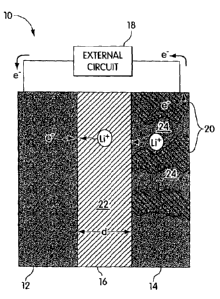
FIG. I is a schematic illustration showing an anode/cathode system that can be
used
in accordance with the present invention;
FIG. 2 is another schematic diagram illustrating another embodiment of the
present
invention illustrating simulated cells;
30 FIGS. 3A - 3D are schematic (cross-section) illustrations showing bipolar
devices
with various reticulated electrodes according to another embodiment of the
present
invention;
CA 02729504 2011-01-25
-6-
FIG. 4 is a schematic illustration showing a bipolar device having a
perforated
structure according to another embodiment of the present invention;
FIG. 5 is a graph showing electrolyte volume fraction as a function of
distance in an
electrode according to one embodiment of the present invention;
FIG. 6 is a graph predicting a normalized cumulative ionic resistance in a
greater
porosity structure in a bipolar device according to one embodiment of the
present invention;
FIG. 7 is a graph showing a normalized cumulative potential drop in a greater
porosity structure in a bipolar device according to one embodiment of the
present invention;
FIG. 8 is a graph showing the specific energy of a greater porosity structure
as a
l0 function of current density in a bipolar device according to one embodiment
of the present
invention;
FIG. 9 is a graph showing the specific energy as a function of specific power
in a
bipolar device according to one embodiment of the present invention;
FIG. 10 is a graph showing the specific energy as a function of electrolyte
fraction at
1.5 the surface of a graded porosity structure in a bipolar device according
to one embodiment
of the present invention; and
FIG. I l is a graph showing the specific energy as a function of discharge
current
density in a bipolar device having a graded porosity structure according to
one embodiment
of the present invention.
Detailed Description
To improve the intrinsic transport properties of electrochemically active
oxides, a
three-phase porous electrode can be used to improve the rate-limitation. A
carbonaceous
conducting additive and an electrolyte material can he added to the storage
material, lithium,
cobalt oxide, for example, to improve the electronic and ionic conductivity.
Typically, microstructural features control the critical properties of such
materials.
Accordingly, the microstructure of components in such systems is tailored to
optimize
desirable properties and minimize the undesirable ones.
A bipolar device according to one embodiment of the present invention is
schematically depicted in FIG. 1. The bipolar device 10, which can be an
energy storage
system, can use, in one embodiment, a LiCoO2/carbon combination. In some
cases, a solid
polymer energy storage system, such as a battery, can be provided and
comprises an
electrolyte 16, lithium metal anodes 12, and cathodes 14. Energy storage
devices according
CA 02729504 2011-01-25
-7-
to the present invention, such as but not limited to lithium ion batteries,
can be based on
liquid electrolytes. For example, the typical lithium battery has a lithium
foil or a composite
carbon anode, a liquid electrolyte with a lithium salt and a composite
cathode. During
discharge, lithium ions move through the electrolyte from the anode to the
cathode, and then
s intercalate into the oxide storage material. To preserve charge neutrality,
electrons are
driven through the external circuit 18 to complete the electrochemical
reaction. Preferably,
the electrode should provide fast transport for both electrons and lithium
ions.
Realizable energy and power density is typically influenced by system design,
including, for example, component arrangement and selection. Typical high-
performance
to rechargeable energy storage systems are of laminate construction, and can
use composite
electrodes that are typically a mixture of active material, hinder, and
conductive additive.
The system can be flooded with organic liquid electrolyte. The thickness of
the cathode in a
lithium-ion battery is typically less than 200 m, and for high power
batteries, less than 100
pm. To maximize the packing density of storage material, for high energy
density, the pore
t5 channels can be made to be tortuous and limited in cross-sectional area. It
is believed that
the rate-limiting transport step is, in most instances Li{ ion diffusion,
through the liquid-
filled pore channels of the composite electrode. Currently the "cell stack"
can he two metal
foil current collectors, anode, separator, and cathode, that is about 250 Elm
thick.
A lithium ion battery will be used to generally describe the various aspects
of the
20 present invention. The description of such a lithium ion bipolar device is
meant to he
exemplary and the use of the various features and aspects of the present
invention to other
systems is considered to be within the scope of the present invention. For
example, the
below described reticulated, perforated or controlled porosity structures can
be used for
energy storage or energy conversion systems including but not limited to
primary
25 (disposable) and secondary (rechargeable) batteries.
The lithium battery can be charged by applying a voltage between the
electrodes 12
and 14, which causes lithium ions and electrons to be withdrawn from lithium
hosts at the
battery's cathode. Lithium ions flow from cathode 14 to anode 12 through
electrolyte 16 to
be reduced at the anode. During discharge, with reference to FIG. 1, the
reverse occurs;
30 lithium ions and electrons enter lithium hosts 20 at cathode 14 while
lithium can be oxidized
to lithium ions at anode 12, which is typically an energetically favorable
process that drives
electrons through an external circuit 18, thereby supplying electrical power
to a device to
which the battery is connected. Thus, during battery operation, for example,
lithium ions
CA 02729504 2011-01-25
-R-
pass through several steps to complete the electrochemical reaction.
Typically, the steps
include, dissolution of lithium at the anode surface, which typically releases
an electron to
the external circuit; transport of the lithium ions through the electrolyte
(which can reside in
pores of a separator and, with porous electrodes, in the electrodes' pores)
separator, for
example, the electrolyte; transport of the lithium ions through the
electrolyte phase in a
composite cathode; intercalation into the active cathode material, which
typically receives
electrons from the external circuit; and diffusion of lithium ions into the
active material
along with electron transport from a current collector to the intercalation
sites.
The lithium dissolution at the anode and the intercalation reaction at the
cathode-
io electrolyte interface can be thermally activated and can be generally
characterized by
reaction kinetics. The charge transfer reactions, typically at the electrodes,
are believed to
be relatively fast at room temperature and, thus, not necessarily rate-
limiting. Nevertheless,
such reactions can be accelerated by increasing the surface area of the
reaction. Reducing
the particle size of the intercalation material can increase the rate of
reaction. Ion
intercalation into an electrode can be characterized by diffusion. For typical
intercalation
oxides at room temperature, the diffusion time, in a typical energy -storage
device, across a
typical distance of about one pm can be about ten seconds. Notably, diffusion
limitations
can be reduced by reducing the oxide particle size but can be addressed by
altering other
diffusion parameters.
Ion transport across the separator 16 typically occurs in two regions, the
separator
region 22 and the electrode region 24. In the former, generally, no
electrochemical reactions
occur and transport phenomena can be governed by the separator physical
properties. The
rate associated with this phenomenon can be reduced by designing or optimizing
separator
physical properties or by minimizing the transport distance across the
separator. In the
latter, ion transport can occur through the electrolyte-filled pore channels
or network
structures of the electrode. The ion transport can be affected by, for
example, the tortuosity
of the average ion transport path. In some systems, the ionic current changes
with electrode
depth because of the electrochemical reaction.
The effective ionic conductivity in a composite structure 12 or 14 is believed
to
decrease rapidly with decreasing pore volume fraction, said pores being filled
with
electrolyte. Accordingly, in one embodiment, the present invention provides an
electrode
structure 12 or 14 that favors or promotes ion transport. For example,
according to one
embodiment, the present invention provides a system comprising lamellar
particles arranged
CA 02729504 2011-01-25
-9-
to be substantially parallel to the direction of current flow. With such a
lamellar
microstructure, the volume fraction of active material can be increased
without reducing
ionic conductivity.
According to another embodiment, the present invention provides a bipolar
device
10 having a design in which the current collector and electrolyte mass is
minimized while
the anode and cathode structures mass are maximized. In one embodiment, the
diffusion
length, d, or path that electrodes or ions must traverse is minimized and the
interfacial area
exposed to the ions or electrons is maximized.
That is, in one embodiment, the system can include components or structures
that
can be reticulated or has a reticulated interface so that an interface area
can be increased. In
this way, the increased interfacial perimeter increases the available sites
for reaction of, for
example, ionic species. Many different reticulation patterns can be used
according to the
present invention including the reticulated structures shown schematically in
FIGS. 3A - 31).
In one embodiment, the aspect ratio I/a of this feature can be varied where I
is the length of a
protrusion (or indentation), described below, and a is its width or thickness.
Such a bipolar
device can be fabricated by a variety of methods or procedures, as described
below. FIGS.
3A - 3D show systems having a variety of reticulated structures. In FIG. 3A,
system 10 has
a reticulated anode 12 having a plurality of extensions 28 extending into and
in ionic
communication with electrolyte matrix 16. In this embodiment, cathode 14 is
shown as
non-reticulated. Similarly, according to another embodiment, FIG. 3B shows
system 10
having a reticulated anode 12 and a reticulated cathode 14, each having
protrusions 28 and
complementary indentations 26 that are separated from each other at a uniform
distance.
Anode 12 and cathode 14 can be in ionic and/or electronic communication with
electrolyte
16. In FIG. 3C, system 10 has complementary reticulated structures 12 and 14,
each being
interdigitated, the reticulations having a length, 1, and a width or
thickness, a. In FIG. 31),
system 10 has reticulated structures 12 and 14, each in electronic
communication with a
current collector 30. The reticulations form convexities 28 that are at a
separation distance,
d, from correspondingly-shaped concavities 26.
In addition to producing a single layer cell, or a stack, a multilayer cell
with a higher
energy density and power density can be achieved with the same materials in a
planar
interface design. The present invention provides systems or cells with a wide
range of
properties, for example, discharge rates, power densities, that can be made of
the same set of
materials. This provides flexibility and can lead to a more efficient design,
prolotyping and
CA 02729504 2011-01-25
-10-
manufacturing sequence, as well as providing a tailorable or customizable
bipolar device. A
bipolar device having structures of reticulated interface can be tailored for
the purposes of
controlling and optimizing charge and discharge kinetics.
In the present invention, "reticulated interface" or "interdigitated
electrode" refers to
a battery 10 that has a structure, such as a positive and/or a negative
electrode 12 and 14
each of which can be connectable to a current collector 30 everywhere,
including cases
where the positive and negative electrodes serve as their own current
collector and having a
morphology such that the surface exposed is reticulated, having convexities 26
or
protrusions 28 and, correspondingly, concavities or indentations, sufficient
to produce
to features with a thickness or width that is less than the maximum thickness
or width of each
electrode. Such features may he periodic and regularly spaced or aperiodic or
random. The
morphology of the structures exhibit shape complementarity towards one another
such that
where one electrode has a protrusion, the other tends to have a indentation of
similar shape
and dimension. The positive and negative electrode can be separated everywhere
along
is their "mating" interface by a layer or region of electrolyte 16. In some
embodiments,
especially with respect to systems with shape complementary structures, the
layer of
electrolyte 16 can be thin and can have a relatively uniform thickness.
It is preferred that the spatially-averaged thickness of the layer of
electrolyte or
separator between positive and negative electrodes be less than about 100
microns,
20 preferably less than about 50 microns, still preferably less than about 25
microns, and still
preferably less than about 10 microns. It is also preferred that the
reticulated features of the
positive and negative electrode have a thickness, when averaged along the
length of the
protrusion or indentations, that is less than about 100 microns, preferably
less than about 50
microns, still preferably less than about 25 microns, and still preferably
less than about 10
25 microns. Such designs can decrease the volume of the systems that would
normally be
consumed by the separator, electrolyte, binder, conductive additive, and other
inert
components that, in some embodiments, do not store lithium, and thereby
increases the
energy density of the battery on a volume or weight basis.
Having the above stated dimensions, this design also has improved power on a
30 volume or weight basis compared to batteries of conventional design,
because the ion
diffusion distance can be decreased. In a conventional laminated battery
design in which the
thickness of the positive and negative electrodes are approximately uniform,
during
charging or discharging the ions must diffuse across the thickness of the
electrodes. In a
CA 02729504 2011-01-25
- 11 -
conventional lithium ion device, the electrode thickness is typically about
100 to about 200
micrometers. In most such systems the rate of transport of lithium ions across
the electrode
thickness limits the power. The transport rate of electrons is believed to be
much higher and
is not necessarily rate-limiting. In the present invention, when applied to a
lithium ion
battery, the lithium ion diffusion distance can be decreased, from a value
equal to the
electrode thickness to a value equal to the lateral dimensions of the
reticulated or
interdigitated features.
In another embodiment, the present invention provides increasing the
interfacial area
between an electrode of a bipolar device and a separator or electrolyte to
reduce the
1o diffusion distance or to minimize the length of diffusion paths. In some
cases, as shown in
schematically in FIG. 4, the present invention provides a system 10 having a
perforated
structure, such as an electrode 12 and 14, that has a plurality of channels 32
defined therein.
In one embodiment, the plurality of channels can be filled with electrolyte
material. Such a
structure can improve ionic diffusion by minimizing diffusion tortuosity.
Thus, the effective
diffusion length can be decreased. In some cases, perforated preferred
electrodes can be
used as a composite cathode in lithium ion batteries. In another embodiment,
the present
invention provides a thin film battery wherein the electrode can be a dense
single phase
material that has a plurality of channels filled with solid electrolyte 16.
The right side of
FIG. 4 shows a cross-section along a-a of electrode 14. The cross-section
shows electrolyte
16 in the channels 32 of electrode 14. The channels can extend through and
across the
electrode, from the front at interface 34 with separator 16 to the back near
current collector
30. Channels 32 provide ionic communication between the back of the
electrolyte and the
region near the back of an electrode. This alternate transport path should
reduce the
transport distance by removing tortuosity that an ionic species may travel.
Channels 32 can
have a variety of cross-sectional shapes such as, but not limited to circular,
as shown in FIG.
4, rectangular or polygonal.
The present design can also provide a system wherein the charge or discharge
characteristics can be selectively tuned by altering the dimensions of the
reticulated or
interpenetrating features. Microfabrication approaches such as those described
below allow
these feature shapes and dimensions to be readily varied thus providing
improved control
over system characteristics without relying on the type of material. This
improves design,
prototyping, and manufacturing, compared to conventional energy storage
systems where
materials formulations are typically empirically adjusted to achieve desired
properties. In
CA 02729504 2011-01-25
-12-
another embodiment, the present invention provides improved ion transport in a
composite
structure, such as an electrode, by adjusting the ionic conductivity relative
to the current
distribution in the structure. When a charge transfer current in the electrode
particles is rate-
limiting, the current carried by the electrolyte phase in the electrode can
decrease with
depth. Such a phenomenon typically indicates that the ionic conductivity of
the electrolyte
phase near the region away from the electrolyte separator may not he critical
while a high
ionic conductivity near the electrode surface requires rapid ion transport
towards the bulk of
the electrode structure. Accordingly, in one embodiment, the present invention
provides
improved transport rates by grading the porosity, or porosity density, of the
electrode
to structure. A high volume fraction of electrolyte near the interface, with
the bulk electrolyte,
can improve ionic conductivity in the region where ion current can be high, to
improve rate
capability, while a higher fraction of the active material in the depth of the
electrode allows
retaining a high energy density.
The present invention provides a variety of graded porosity arrangements
including,
l5 but not limited to, linear, concave up and concave down porosity gradients.
An electrode,
for example, with a linear porosity gradient typically has a continuously, or
at least a non-
discretely, varying porosity from one region to another region. For example,
an electrode
can have a linearly varying porosity, filled with electrolyte, in one
embodiment, so that a
porosity of 0.4 can be at the front 36 of the electrode, near the electrolyte,
and a porosity of
20 0.2 can be at the back 38 of the electrode, near the current collector. The
back refers to the
region of an electrode that is in electronic communication with a current
collector and the
front refers to the region of an electrode that is positioned adjacent the
separator electrolyte.
In other embodiments, the electrode has a porosity that can have concave up or
concave
down profile.
25 The porosity can average from about 10% to about 70%. It is believed that
if the
porosity is too high, above about 80%, then the framework may be structurally
unstable; if
the porosity is too low, below about 10%, then there is only an incremental
increase in
power or energy density. Accordingly, the average porosity is, preferably from
about 20%
to about 50%. In another embodiment, the average porosity is from about 30% to
about
30 45%. In some embodiments, the porosity gradient in an electrode, from the
current collector
toward the electrolyte or the other electrode, varies by at least about 10%
from the average
porosity, preferably, at least about 20%, more preferably, at least about 30%.
In other
embodiments, at any cross-section of an electrode perpendicular to a line
connecting the
CA 02729504 2011-01-25
-13-
center of mass of the current collector and the center of mass of the other
electrode, the
porosity variation is uniform to about +/-10%, preferably about +/-5%, more
preferably,
about +/-3%, and even more preferably about +/-I%.
Thus, the system can have structures that have a porous network in a
framework.
The porous network can be conically interconnected so that ions can diffuse to
the cavities
defining the porosity at any location within the porous structure. For
example, a lithium ion
can diffuse from the bulk electrolyte to any ionically interconnected location
in a porous
electrode.
These graded porosity gradients are graphically illustrated in FIG. 5. In FIG.
5, the
to average porosity is about 0.3 and each of the graded porosity electrodes
has a porosity of
about 0.4 at the front of the electrode, which corresponded to an electrolyte
fraction of 0.4.
The performance of the bipolar system shown in the figures relates to a
typical
LiMn2O4 spinel cathode with a EC/DEC/LiPF6 electrolyte and either a MCMB
carbon or
lithium anode schematically illustrated in FIG. 2. The mesoporous carbon
microbeads
(MCMB) carbon anode was used for evaluations of graded porosity electrodes.
For
discharges, a spinel cathode was assumed with an initial lithium content of
Li0_1705Mn2O4.
The systems were simulated to be discharged to a cutoff of about 3.5 V. The
cathode
thickness was assumed to be about 200 pm; the electrolyte thickness was
assumed to he
about 52 m and the anode thickness was assumed to be about 100 m. In the
figures,
various gradients are shown for an average porosity of 0.3.
FIG. 6 is a graphical illustration of the normalized cumulative ionic
resistance as a
function of electrode depth for each of the graded porosity electrodes shown
in FIG. 5.
Each of the graded porosity electrodes had a predicted lower cumulative ionic
resistance
than a conventional electrode near the surface and throughout the electrode.
FIG. 7 is a
graphical illustration of the normalized cumulative potential drop as a
function of electrode
depth for each of the graded porosity electrodes shown in FIG. 5. Each of the
graded
porosity electrodes has a lower potential drop than a conventional electrode
near the surface
as well as throughout the electrode. FIGS. 6 and 7 show that the graded
porosity electrode
has better ionic transport and potential properties that should translate to
higher power and
energy densities. Such performance can be graphically illustrated in FIGS. 8
and 9, which
show, respectively, the specific energy relative to the current density and
specific power, for
a variety of graded porosity electrodes. FIG. 9 shows that the systems with
graded porosity
electrodes would supply more energy at a given power than a conventional
electrode
CA 02729504 2011-01-25
-14-
system. Moreover, FIG. 10, which is a graphical illustration of the specific
energy as a
function of porosity (electrolyte fraction at the electrode surface), shows
that as the
discharge current increases, the optimum electrode grading shifts from a
slight porosity to
more severe gradients at high current densities. It is believed that the shift
follows from
decreasing electrode utilization with increasing current where lower ion
transport properties
at the back of the electrode, especially for highly graded electrodes,
inhibits utilization at
low and moderate discharge rates. FIG. 11, which is a graphical illustration
of specific
energy as a function of discharge current density for systems with concave up,
concave
down and linearly gradient porosity electrodes, shows that the graded porosity
systems have
io higher specific energy compared to a conventional, homogeneous electrode
system,
especially at the intermediate discharge rate regime.
In accordance with another embodiment, the electrode has a porosity gradient,
from
the current collector to the other electrode or the electrolyte, that has a
slope that varies by
less than or no more than 5% at any location along the electrode, preferably,
by less than or
no more than 10%, more preferably, by less than or no more than 15%. The
change in slope
can be stepwise or smooth.
In another embodiment, the structures have a mating surface that is
reticulated with a
surface area that is at least 1.5 times the theoretical surface area of a
smooth, non-reticulated
structure, preferably, the reticulated surface area is at least about 2.5
times, more preferably,
at least about 3 times, even more preferably, at least 4 times, and most
preferably, at least
about 5 times.
In another embodiment, the reticulations have an aspect ratio that is at least
about 2,
preferably at least about 2.5, more preferably at least about 3.0, more
preferably at least 3.0,
more preferably at least about 4.0, and most preferably, at least about 5Ø
In another embodiment, the protrusions and indentations are separated by an
average
distance of less than about 100 microns. Preferably, the separation distance
is less than
about 50 microns, more preferably, less than 25 microns, most preferably, less
than about 10
microns.
The function and advantage of these and other embodiments of the present
invention
will be more fully understood from the examples below. The following examples
are
intended to illustrate the benefits of the present invention, but do not
exemplify the full
scope of the invention.
CA 02729504 2011-01-25
-15-
EXAMPLES
Prophetic Example 1. Lithium Battery Prepared by Sequential Deposition
A suspension can be prepared of a fine powder lithium storage cathode such as
LiCoO2, LiNi02i LiMnO2, LiMn2O4, LiFePO4i V205, Li3Bi, Li3Sb, or other such
cathodes
well-known to those skilled in the art, in a solvent with a binder, optionally
a conductive
additive such as carbon, and other additives well-known to impart
characteristics to the
suspension allowing it to be deposited in thin layers using stenciling, screen
printing, ink-jet
printing, or lithographic methods selected to allow a lateral resolution to
the printed layer
to that is within the desired dimensional ranges. A separate like suspension
can be prepared of
a fine powder lithium storage anode such as carbon, Sn, Sb, Al, Zn, Ag, LiAI
or other anode
materials known to those skilled in the art. The cathode suspension and anode
suspension
are deposited layer by layer, providing a periodic or aperiodic reticulated or
interdigitated
structure as described above and as shown in Figure 3. Electronic contact,
shorting,
l5 between the cathode and the anode is avoided by selecting the solvent and
binder system
such that a continuous (wetting) surface layer of the binder forms upon
drying, and/or by
depositing the layers such that, within the same layer, cathode patterns and
anode patterns
are adequately separated. Optionally, a third suspension containing binder and
no cathode
or anode or conductive additive can be deposited in a pattern at the interface
of the cathode
20 and anode patterns to ensure electronic isolation of the two.
A metal foil or fine mesh current collector made of, for example, aluminum or
copper, can be used as the substrate upon which layers are deposited. Aluminum
is
preferred when the cathode compound forms a first continuous layer and copper
is preferred
when the anode forms a first continuous layer. After sequential deposition is
complete, and
25 the assembly is dried and, optionally, heated for consolidation, a second
current collector
can be applied to the surface of the layered battery. Optionally, the top
current collector is
formed by printing as a conductive ink using techniques such as those used for
forming
patterned interconnects as those used by those skilled in the art of
electronic device
fabrication. Optionally, the battery is deposited on an insulating film such
as, but not
30 limited fo, polyethylene or polyester such as MYLAR x0 film, available from
the F.I. du Pont
de Nemours and Company (Wilmington, Delaware), from which the battery can be
subsequently removed and current collectors can be applied to form contacts
with the anode
and cathode.
CA 02729504 2011-01-25
16-
The binder is, for example, a solid polymer electrolyte. This should obviate
the need
for liquid electrolyte in the battery, and, in some instance, serves to bind
the particles
securely together in the assembled device while allowing liquid electrolyte to
be infused
(flooded) throughout the battery. An example of suitable solid polymer
electrolyte includes,
is not limited to, (poly)ethylene oxide in which a lithium salt such as
lithium perchlorate or
lithium triflate has been added. An example of a binder and liquid electrolyte
that remains
dimensionally stable, i.e., the electrolyte does not dissolve the hinder, is
(poly)ethylene
difluoride (PVdF) and ethylene carbonate-dimethyl carbonate (EC:DMC) in a 1:1
molar
ratio to which a lithium salt has been added.
Prophetic Example 2: Battery Produced by Printing and Coating
A first electrode with a reticulated or interdigitated structure, either
cathode or
anode, is prepared using the materials and methods of Example 1. At the free
surface of the
printed structure, a continuous film of a binder or polymer electrolyte can be
formed. The
is film can form a physical separator between anode and cathode. The film can
be formed by
self-segregation (wetting) of the binder solution to the free surface of the
printed electrode.
Optionally, the surface film can be formed by coating with a liquid binder or
electrolyte
solution followed by drying, or by vapor deposition techniques known to those
skilled in the
art of thin film materials preparation.
A conformal coating of a liquid suspension can be applied to the formed
structure to
create the counter electrode. The indentations of the latter fill in
complementary fashion to
the structure of the first electrode, leaving a smooth and flat outer surface
to which a current
collector is subsequently applied. Multiple coatings may be used to achieve
conformal
filling. The system can then be dried and optionally heated for consolidation.
A current
collector can be applied to one or both surfaces to complete the system.
Prophetic Example 3: Battery Produced by Embossing and Coating
A layer of a first electrode, either cathode or anode, formulated of the
materials and
by the methods of Example 1, is cast or coated in a layer upon a metal foil
current collector
or an insulating film. This layer is formulated by methods known to those
skilled in the art
to have rheological characteristics appropriate for thick film processing, for
example, by
screen printing, tape casting, web coating, and similar processes. The surface
of the first
layer is then embossed with a die to leave a reticulated surface with
dimensions as desired.
CA 02729504 2011-01-25
17-
To this shaped surface is applied a counterelectrode by the conformal coating
material and
process described in Example 2. The assembly is dried and optionally heated
for
consolidation and a current collector is applied.
A film of binder or electrolyte is applied before or after the embossing step,
and
before coating with the counterelectrode formulation.
Prophetic Example No. 4: Subtractive Patterning Followed by Filling
A layer of a first electrode, either cathode or anode, formulated of the
materials and
by the methods of Example 1, is cast or coated in a layer upon a metal foil
current collector
to or an insulating film. Optionally the electrode is cast or coated as a
suspension upon a metal
foil current collector and fired to obtain a continuous solid film of the
storage material, or
deposited as a solid film by a vapor deposition process known to those skilled
in the art,
such as sputtering, evaporation, chemical vapor deposition. The layer of first
electrode is
subtractively patterned, that is, material is removed, to form the reticulated
or interdigitated
electrode topology of the invention, by lithographic masking followed by
chemical or
reactive-ion etching, laser removal, or other such methods known in thick and
thin film
materials processing. Upon the patterned first electrode is optionally
deposited a film of
binder or electrolyte, followed by coating with the counterelectrode so as to
conformally fill
the pattern in the first electrode, by the method of Example 3.
Prophetic Example 5: Graded Porosity Electrode Produced by Differential
Sedimentation
It is well-known to those skilled in the art of powder processing that the
Stokes'
settling rate of particles in a fluid is a function of the size and shape of
the particles, the
difference in density between the particle and the fluid within which it is
settling, and the
fluid viscosity. For the same particle material, smaller particles tend to
settle slower than
larger particles, and anisometric particles such as rods of large length to
diameter ratio, or
plates of large width to thickness ratio, settle at a slower average rate than
spheres or
equiaxed particles of identical volume. It is furthermore known that highly
aspected
particles tend to settle to a lower packing density than equiaxed particles of
the same
material. Therefore a method for introducing a porosity gradient into a layer
of storage
electrode fabricated from a powder mixture or suspension is use a mixture of
particle sizes
and shapes.
A suspension is made of a cathode oxide powder in which the powder contains a
distribution of particle sizes and shapes. Equiaxed particles are mixed with
platelet-shaped
CA 02729504 2011-01-25
-18-
particles, with the particles sizes selected such that the equiaxed particles
have a higher
Stokes' settling velocity. The powder is formulated with a binder (such as
PVdF), a fine
conductive additive (such as high surface area carbon) and a solvent to
produce a tastable
suspension. The suspension is formulated to allow differential sedimentation
of the cathode
oxide particles within a few minutes to a few hours after casting a film from
the suspension.
The film is cast, printed, or coated on a metal foil current collector or an
insulating film,
whereupon differential sedimentation occurs under the force of gravity
resulting in a higher
packing density of equiaxed particles in the portion of the electrode adjacent
to the metal
current collector, and a lower packing density of anisometric particles away
from the metal
current collector. This introduces a desired porosity gradient in the
electrode. After drying,
the electrode is laminated with a separator and a counterelectrode and infused
with organic
liquid electrolyte to produce a battery cell. Optionally, a cathode oxide with
high electronic
conductivity, such as LiMgo,o5CoU.9502, is used and no carbon additive is
used.
A graded porosity carbon anode is produced in like manner, using carbon powder
selected to have a mixture of equiaxed particle shapes and anisometric
particles shapes, as
well as differences in density that allow the Stokes' settling rates to be
adjusted. In one
instance MCMB are used as the equiaxed carbon particle which settles more
rapidly and
forms a more densely packed region adjacent to the current collector, and
flake graphite
with platelet particle shape is used as the anisometric carbon particle which
settles more
slowly and forms the lower packing density region adjacent to the separator.
The porosity
gradient is adjusted by selecting the relative amounts of the particle forms
and the size of the
MCMB and flake graphite particles.
Prophetic Example 6: Graded Porosity Electrode Produced by Differential
Sedimentation of
a Fugitive Filler
In this example, a suspension is used to form a cast, printed, or coated layer
of
electrode as in Example 5. However, the electrode storage material is mixed in
the
suspension with one or more additional solid materials which upon heating are
removed,
thereby leaving behind porosity. Therefore the solid material that is removed
is a "fugitive"
pore former. The density, particle size and size distribution, and particle
shape of the
electrode storage material and the fugitive pore former are selected to
provide a differential
Stokes' settling rate giving in the final product a more densely packed
storage material
CA 02729504 2011-01-25
-
19-adjacent to the current collector, and less densely packed storage material
adjacent to the
separator.
In one instance the storage material is an oxide cathode such as LiCoO2,
LiMgo.o5Coo9502, LiMnO2, or LiFePO4. The fugitive pore former is MCMB,
selected to
have a particle size giving a slower Stokes' settling rate than the cathode
oxide. A
suspension is prepared containing these two solids as well as a solvent and
optionally a
hinder, the specific formulation being selected to allow differential
sedimentation of the
cathode oxide and MCMI3. The suspension is cast, printed, or coated on a metal
current
collector and fired in an oxidizing ambient that pyrolyses the MCMB and
sinters the cathode
oxide to form a connected layer. The sintered porous cathode layer contains a
desired
porosity gradient once the MCMB has been removed.
In another instance, the fugitive pore former consists of particles of an
organic or
inorganic compound with a melting point between about 0 C and 800 C. The
preparation
of the suspension and the casting process are carried out below the melting
point of the
compound. Subsequently, the cast, printed, or coated film is heated above the
melting point
of the organic compound allowing it to be drained or evaporated from the
porous electrode,
leaving a desired porosity gradient.
In still another embodiment, the fugitive pore former is a solid with a high
vapor
pressure, such as napthalene, and which is removed by sublimation rather than
melting,
leaving a desired porosity gradient.
Those skilled in the art should appreciate that all parameters and
configurations
described herein are meant to be exemplary and that actual parameters and
configurations
will depend upon the specific application in which the systems and methods of
the present
invention are used. Those skilled in the art should recognize, or be able to
ascertain, using
no more than routine experimentation, many equivalents to the specific
embodiments of the
invention described herein. For example, the selection and sizing of the
channels in
perforated electrodes is considered to require no more than routine
experimentation. It is,
therefore, to be understood that the foregoing embodiments are presented by
way of
example only and that, within the scope of the appended claims and equivalents
thereto, the
invention may be practiced otherwise than as specifically described. The
present invention
is directed to each feature, system, or method described herein. In addition,
any
combination of two or more features, systems or methods, if such features,
systems or
methods are not mutually inconsistent, is considered to be within the scope of
the present
CA 02729504 2011-01-25
-20-
invention. For example, the use of channels in reticulated electrodes or the
incorporation of
a porosity gradient with perforated or reticulated electrode is considered to
be within the
scope of the present invention.