Note: Descriptions are shown in the official language in which they were submitted.
CA 02729544 2016-01-11
,
' 67363-1717
ELECTRONIC DOOR LOCK WITH MODULAR COMPONENTS
BACKGROUND
[0001] The present invention relates to access control systems,
and more particularly
to an electronic door lock used in an access control system.
[0002] Access control systems may be upgraded periodically.
Upgrades may include
newer versions of software, firmware, hardware, or a combination thereof.
Upgrades may be
performed as maintenance or for user preference. For example, a user may wish
to change
from an offline access control system to an online access control system.
Alternatively, a user
may wish to change from a wired access control system, in which all
communication occurs
over physical, wired connections, to a wireless system, in which some or all
of the
communication is performed wirelessly. Traditionally, an upgrade from a wired
system to a
wireless system would require the purchase of new electronic door locks with
wireless
capability.
[0003] As a user's needs change, it may be desirable to change other
features of the
access control system. For example, a user may wish to convert from a system
that uses a
keypad input to a system that uses a biometric input. Because locks are
designed to function
with a specific input device, a switch from one type of input device to a
different type of input
device generally requires the purchase of a new set of door locks. Thus,
upgrading an access
control system is often expensive and time consuming.
1
CA 02729544 2016-01-11
67363-1717
[0004] In one construction, the invention provides an electronic door
lock that mounts
to a door. The door includes an inner side and an outer side, and the
electronic door lock is
operable to control access to an access controlled area positioned adjacent
the inner side of the
door. The electronic door lock includes an outer base connected to the outer
side of the door,
an inner base connected to the inner side of the door, a locking mechanism
coupled to the
door and movable between a locked position and an unlocked position in
response to a control
signal, and a control circuit disposed within the inner base and operable to
generate the
control signal in response to an input credential. An attachment interface is
at least partially
formed as part of the outer base. A plurality of different types of credential
readers is
selectively attachable and removable from the attachment interface when the
outer base is
attached to the door to electrically connect a selected one of the plurality
of different types of
credential readers to the control circuit to provide the input, each of the
credential readers
being fully supported by the outer base when attached to the attachment
interface. A
communication module is connected to the control circuit, and the
communication module is
operable to communicate with a device that is separate from the electronic
door lock. A first
anti-tamper wall extends in a horizontal direction from the outer base and
positioned between
the attachment interface and the locking mechanism to inhibit access to the
locking
mechanism from the attachment interface; and a second anti-tamper wall extends
in the
horizontal direction from the outer base and positioned between the first anti-
tamper wall and
the locking mechanism to inhibit access to the locking mechanism.
2
CA 02729544 2016-01-11
=
=
67363-1717
"-
= =
[0005] In another construction, the invention provides an
electronic door lock that mounts
to a dobr The door includes an inner side and an outer side, and the
electronic door lock is
- operable to control access to an access controlled area positioned adjacent
the inner side of
= the door. The electronic door lock includes an outer base supported by
the outer side, a
= locking mechanism coupled to the door and moveable between a locked
position and an
unlocked position, and a control circuit coupled to the door. The control
circuit is configured
to selectively move the locking mechanism between the locked position and the
unlocked
position to control access to the access controlled area. An attachment
interface is coupled to
the outer base and includes a mounting portion and a first connector that
extends from the
mounting portion. The first connector is in electrical communication with the
control circuit..
= An outer escutcheon is supported by At least one of the outer base and
the door. The outer
= escutcheon is positioned to substantially cover the outer base and
includes an aperture
positioned adjacent the attachment interface to expose the attachment
interface. A credential-
reader includes a surface sized and shaped to geherally correspond to the
mounting portion
and a second connector configured to mate with. the first connector. The
credential reader is
= removably mountable to the attachment interface to electrically connect
the credential reader
tO the control circuit.
[0006] In yet another construction, the invention provides an
electronic door lock that
mounts to a door. The door includes an inner side and an outer side, and the
electronic door
=
lock is operable to control access to an access controlled area positioned
adjacent the inner
side of the door. The electronic door lock includes an inner base supported by
the inner side, '
a locking meohanism coupled to the door and moilable between a locked position
and an
unlocked position, and a control circuit coupled to the door. The control
circuit is configured
to selectively move the locking mechanism between the locked position and the
unlocked
= position to control access to the access controlled area. A communication
module is coupled
to the control circuit to allow the electronic door lock to communicate with a
device that is
different from the electronic door lock, and the communication module is
positioned in the
inner base adjacent the inner side. The communication module is removably
coupled to the
control circuit and the inner base. An inner escutcheon is supported by at
least one of the
inner base and the door, and the inner escutcheon is positioned to
substantially cover the
inner base. The inner escutcheon includes an aperture positioned adjacent the
=
communication module to expose the communication module and to allow the
communication module to be removed and replaced through the inner escutcheon
aperture. A
cover is removably coupled to the inner escutcheon, and the cover and the
inner escutcheon
cooperate to close the inner escutcheon aperture and to cover the
communication module.
3
CA 02729544 2016-01-11
67363-1717
[0007] In yet another construction, the invention provides an an
electronic door lock
that mounts to a door, the door including an inner side and an outer side and
the electronic door
lock operable to control access to an access controlled area positioned
adjacent the inner side of
the door, the electronic door lock comprising: an outer base connected to and
supported by the
outer side; an inner base supported by the inner side; a locking mechanism
coupled to the door
and moveable between a locked position and an unlocked position; a control
circuit disposed
within the inner base and configured to selectively move the locking mechanism
between the
locked position and the unlocked position to control access to the access
controlled area; an
attachment interface coupled to the outer base and including a mounting
portion and a first
connector that extends from the mounting portion, the first connector in
electrical
communication with the control circuit; a first anti-tamper wall extending in
a horizontal
direction from the outer base and positioned between the attachment interface
and the locking
mechanism to inhibit access to the locking mechanism from the attachment
interface; a second
anti-tamper wall extending in the horizontal direction from the outer base and
positioned
between the first anti-tamper wall and the locking mechanism to inhibit access
to the locking
mechanism; an outer escutcheon supported by at least one of the outer base and
the door, the
outer escutcheon positioned to substantially cover the outer base and
including an aperture
positioned adjacent the attachment interface to expose the attachment
interface; and a credential
reader that includes a surface sized and shaped to generally correspond to the
mounting portion
and a second connector configured to mate with the first connector, the
credential reader
removably mountable to the attachment interface to electrically connect the
credential reader to
the control circuit, such that when the credential reader is mounted to the
attachment interface,
the outer base fully supports the credential reader and when the credential
reader is not mounted
to the attachment interface, the outer base remains connected to the outer
side of the door.
[0007a] In yet another construction, the invention provides an electronic
door lock that
mounts to a door, the door including an inner side and an outer side and the
electronic door lock
operable to control access to an access controlled area positioned adjacent
the inner side of the
door, the electronic door lock comprising: a locking mechanism coupled to the
door and
moveable between a locked position and an unlocked position; an attachment
interface coupled
to the outer side and including a mounting portion; one of a keypad, proximity
detector,
3a
CA 02729544 2016-01-11
67363-1717
proximity detector with built-in keypad, magnetic stripe reader, magnetic
stripe reader with
built-in keypad, and biometric reader, each of the keypad, proximity detector,
proximity
detector with built-in keypad, magnetic stripe reader, magnetic stripe reader
with built-in
keypad, and biometric reader removably mountable to the mounting portion such
that the
attachment interface fully supports the one of the keypad, proximity detector,
proximity detector
with built-in keypad, magnetic stripe reader, magnetic stripe reader with
built-in keypad, and
biometric reader; a control circuit coupled to the door and configured to
selectively move the
locking mechanism between the locked position and the unlocked position to
control access to
the access controlled area, the control circuit including software or firmware
operable to receive
an input from each one of the keypad, proximity detector, proximity detector
with built-in
keypad, magnetic stripe reader, magnetic stripe reader with built-in keypad,
and biometric
reader; an outer base supported by the outer side, wherein the attachment
interface is coupled to
the outer base, and further including a first anti-tamper wall extending in a
horizontal direction
from the outer base and positioned between the attachment interface and the
locking mechanism
to inhibit access to the locking mechanism from the attachment interface; and
a second anti-
tamper wall extending in the horizontal direction from the outer base and
positioned between
the first anti-tamper wall and the locking mechanism to inhibit access to the
locking mechanism.
[0008] Other aspects of the invention will become apparent by
consideration of the
detailed description and accompanying drawings.
BRIEF DESCRIPTION OF THE DRAWINGS
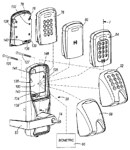
[0009] Fig. 1 is a side view of an electronic door lock mounted to a
door.
[0010] Fig. 2 is a schematic illustration of the electronic door lock
of Fig. 1 and a
plurality of credential readers configured for mounting on the electronic door
lock.
[0011] Fig. 3 is a schematic illustration of the electronic door lock
of Fig. 1 and a
plurality of communication module covers and a plurality of battery covers
configured for
mounting on the electronic door lock.
3b
CA 02729544 2010-12-24
WO 2009/158181 PCT/US2009/046628
[0012] Fig. 4 is a perspective view of the electronic door lock of Fig. 1
including an
attachment interface.
[0013] Fig. 5 is a perspective view of a portion of the electronic door
lock of Fig. 1
illustrating a communication module.
[0014] Fig. 6 is a perspective view of a portion of the electronic door
lock of Fig. 1
illustrating another construction of a communication module.
[0015] Fig. 7 is a sectional view of the electronic door lock of Fig. 1
taken along line 7-7
of Fig. 2.
[0016] Fig. 8 is a schematic illustration of an access control system
including the
electronic door lock of Fig. 1.
[0017] Fig. 9 is a schematic illustration of an electromechanical system of
the door lock
of Fig. 1.
DETAILED DESCRIPTION
[0018] Before any embodiments of the invention are explained in detail, it
is to be
understood that the invention is not limited in its application to the details
of construction and
the arrangement of components set forth in the following description or
illustrated in the
following drawings. The invention is capable of other embodiments and of being
practiced
or of being carried out in various ways.
[0019] Fig. 1 illustrates an electronic door lock 20 mounted to a door 24
and suitable for
use in an access control system 27. The door lock 20 includes an outer portion
28 mounted
on an outer side 32 of the door 24 and an inner portion 36 mounted on an inner
side 40 of the
door 24. The outer portion 28 of the door lock 20 includes an outer escutcheon
44, a
credential reader 48, and an outer handle 52. The inner portion 36 of the door
lock 20
includes an inner escutcheon 56, a communication module cover 60, an optional
pushbutton
64, a battery cover 68, and an inner handle 72.
[0020] The terms "inner" and "outer" are used herein to differentiate the
two sides of the
door and should not be considered as limiting the invention in anyway. In
constructions in
4
CA 02729544 2010-12-24
WO 2009/158181 PCT/US2009/046628
which one side of the door is in a secured space and the other side of the
door is not (e.g., an
entry door into a building), the inner side would be in the secured space.
However, some
constructions may position a door within a space in which both sides of the
door are located
within a secure space. In these constructions, one side of the door would be
considered the
inner side while the opposite side would be the outer side. Thus,
constructions are possible in
which components or features described as being positioned on an inner side of
the door
could be positioned on an outer side of the door and visa versa. Thus, the
terms "inner" and
"outer" are sometimes replaced herein with "first" and "second".
[0021] The door lock 20 includes an electromechanical system that allows
for the
movement of a locking mechanism 180 including an actuator 182, a clutch 179,
and a latch
178, which are schematically illustrated in Fig. 9. The latch 178 is movable
by the inner
handle 72 and the outer handle 52 between a locked position and an unlocked
position.
When the latch 178 is moved to the locked position, the latch 178 is extended
away from the
door lock 20 into an opening in a face plate 186 mounted to a door frame 190.
The latch 178
inhibits movement of the door 24 when in the extended position. When the latch
178 is
moved to the unlocked position, the latch 178 is retracted into the door lock
20 and out of
engagement with the face plate 186 to allow a user to open the door 24.
[0022] The actuator 182 moves the clutch 179 between an engaged position
and a
disengaged position to selectively enable and disable the outer handle 52.
When the clutch
179 is in the disengaged position, the clutch 179 disengages from the outer
handle 52 and the
latch 178 such that movement of the outer handle 52 does not cause movement of
the latch
178. Thus, when the clutch 179 is in the disengaged position, a user
positioned adjacent the
outer side 32 cannot gain access to the inner side 40. When the clutch 179 is
in the engaged
position, the clutch 179 is engages with the outer handle 52 and the latch 178
such that
movement of the outer handle 52 causes the latch 178 to move. Thus, when the
clutch 179 is
in the engaged position, a user positioned adjacent the outer side 32 can move
the latch 178,
open the door 24, and gain access to the inner side 40. The actuator 182 can
include an
electric motor, a solenoid, a piezoelectric actuator, a linear actuator, a
mechanically actuated
device, a different suitable actuator, or a combination thereof to move the
clutch 179 to the
desired position when a user uses an appropriate key 74 or presents an
appropriate credential
to the credential reader 48 to allow the user to operate the outer handle 52
and move the latch
CA 02729544 2010-12-24
WO 2009/158181 PCT/US2009/046628
178. In some constructions, the actuator 182 is configured to selectively
enable and disable
the inner handle 72 or both the inner and outer handle.
[0023] Fig. 2 illustrates the outer portion 28 of the door lock 20. A
plurality of input
devices (also referred to as credential readers 48) are illustrated including
but not limited to a
keypad 76, a proximity detector 80, a proximity detector with built-in keypad
84, a magnetic
stripe reader 88, a magnetic stripe reader with a built-in keypad 92, and a
biometric reader 96.
For clarity, the credential reader 48 could include any one of a keypad 76, a
proximity
detector 80, a proximity detector with built-in keypad 84, a magnetic stripe
reader 88, a
magnetic stripe reader with a built-in keypad 92, and a biometric reader 96 as
well as other
types of credential readers such as a smartcard reader, a smartcard reader
with built-in
keypad, a multitech reader, and a multitech reader with built-in keypad. In
fact, the
modularity of the arrangement described herein would allow for the use of
virtually any type
of credential reader desired. The credential readers may include other
features such as audio
beepers and visual interfaces that include light emitting diodes (LEDs). The
credential
readers 48 are configured to mount to a mounting portion of an attachment
interface 100,
which will be described in greater detail with respect to Fig. 4. Each
credential reader 48 is
self-contained and includes all the necessary electrical components and
firmware required for
the credential reader 48 to receive an input credential from a user and output
the credential or
a signal corresponding to the credential to a control circuit 154 (Fig. 9) of
the door lock 20.
For example, the keypad credential reader 76 is configured to receive a user
input (e.g., a
numeric or alphanumeric code) and output the entered credential to the control
circuit 154 of
the door lock 20. The biometric credential reader 96 is configured to receive
a user input
(e.g., a fingerprint, a scan of the user's hand, a vocal input, a scan of the
user's face, a scan of
the user's eye, or other biometric data), process the user input, and output
data to the control
circuit 154 that is representative of the user input. In some embodiments, the
biometric
credential reader 96 may receive user input in the form of a fingerprint and
output the
fingerprint data to the control circuit of the door lock 20. In other
embodiments, the
biometric credential reader 96 may process the input fingerprint and output a
statistical
representation of the fingerprint data or some other value representative of
the fingerprint or
the user that provided the fingerprint.
[0024] The control circuit 154 of the door lock 20, shown in Fig. 5,
includes software or
firmware that is operable to receive a variety of credentials or other signals
from a variety of
6
CA 02729544 2010-12-24
WO 2009/158181
PCT/US2009/046628
different types of credential readers 48. Thus, the user has the option to
purchase a door lock
and separately purchase any of a variety of credential readers 48, some of
which are
illustrated in Fig. 2. The software of the control circuit 154 is configured
to recognize the
type of credential reader 48 attached to the door lock 20 and thus knows what
input to expect
from the credential reader 48. For example, if a keypad 76 is attached, the
software expects a
user code. If a magnetic stripe reader with a built-in keypad 92 is attached,
the software may
be configured to expect both a user code and a magnetic stripe input. The
software is
configured to receive a signal, from each of a plurality of different types of
credential readers
48, that corresponds to the credential input by the user. Thus, no
modification to the software
is required when a user replaces one type of credential reader (e.g., keypad
76, proximity
detection 80, magnetic stripe reader 88, biometric 96, etc.) with a different
type of credential
reader. Of course, modifications to the software may be performed as desired
by the user.
[0025] As
the user's security needs or preferences change, the user may purchase a new
set of credential readers 48 to change the access control system from using
one type of
credential to a different type of credential. Thus, the user may selectively
remove and attach
desired credential readers 48 in the field (e.g., at the user's place of
business). Of course, the
credential readers 48 may also be selectively removed and attached at a
factory or place of
manufacture. In this way, the electronic door lock 20 contains a high degree
of modularity,
interchangeability, and upgradeability. Only some credential readers 48 are
illustrated in Fig.
2 and discussed herein for exemplary purposes, and the invention is not
limited to the types
of credential readers 48 discussed and illustrated herein.
[0026] Fig.
3 illustrates the inner portion 36 of the door lock 20 which includes an inner
base 144 and the inner escutcheon 56 that defines an inner escutcheon aperture
149. A
plurality of communication module covers 104, 108 are illustrated. One cover
104 is
configured to cover a wired communication module, and a second cover 108 is
configured to
cover a wireless communication module, which will be described in detail with
respect to
Figs. 5 and 6. The covers 104 and 108 may also be used to substantially close
or cover the
inner escutcheon aperture 149 when no communication module is present (e.g.,
offline locks).
A first battery cover 112 and a second battery cover 116 are configured to
mount to the inner
escutcheon 56 to cover the batteries and battery holder 118. A four-battery
battery holder
118 is illustrated in Fig. 3, as the construction of Fig. 3 includes 4
batteries. However, if the
user desires longer battery life or the credential reader 48 requires more
power to operate, the
7
CA 02729544 2010-12-24
WO 2009/158181 PCT/US2009/046628
user can use an eight-battery battery holder and mount battery cover 116 to
the inner
escutcheon 56 to cover the batteries and the battery holder. The eight-battery
battery holder
is formed by attaching a second four-battery battery holder to the door lock
and connecting
the second four-battery battery holder to the first four-battery battery
holder 118 in order to
create an eight-battery battery holder.
[0027] The inner portion 36 of the door lock 20 has an optional secondary
locking
mechanism 196 that includes a deadbolt turn 122 and a deadbolt 194. The
deadbolt turn 122
is accessible from inside the access controlled area and is coupled to the
deadbolt 194 to
allow a user to move the deadbolt 194 (Fig. 9) from a locked position, in
which it is extended
and engaged in a second opening in the faceplate 186, to an unlocked position,
in which the
deadbolt 194 is retracted into the door lock 20 and out of engagement with the
second
opening in the faceplate 186. Thus, a user inside the access controlled area
may turn the
deadbolt turn 122 to move the deadbolt 194 into engagement with the opening in
the
faceplate 186, thus inhibiting other users from entering the access controlled
area even when
an appropriate key 74 is used or when appropriate credentials are presented.
[0028] The communication module covers 104, 108 include optional outer
pushbuttons
64, 65 mounted to the communication module covers 104, 108, respectively. A
corresponding internal button 66 is coupled to the inner base 144. When the
cover is
mounted on the inner escutcheon 56, the outer pushbutton 64 or 65 aligns with
the
corresponding internal button 66. When a user positioned inside the access
controlled area
pushes the pushbutton 64, 65, the corresponding internal button 66 is actuated
and sends an
electrical signal to the control circuit. The control circuit receives the
signal and processes
the signal. The internal button 66 may be configured for providing a privacy,
lock, unlock, or
other function. The control circuit may be programmed to ignore signals
received from the
pushbutton to effectively disable the pushbutton 66, or the control circuit
may be
programmed to change the operating mode of the door lock for some period of
time or until a
second signal is received. For example, the door lock may change from a
standard mode of
operation to a restricted access mode. When the pushbutton 66 is activated,
the door lock 20
may only allow a select number of users to enter the access controlled area,
temporarily
denying assess to all others who present valid credentials. Of course, other
operating modes
are also possible and may be predefined and programmed into the electronic
door lock
software. If the communication module cover 104, 108 does not include an outer
pushbutton
8
CA 02729544 2010-12-24
WO 2009/158181
PCT/US2009/046628
64, 65, then the corresponding internal button 66, while still present in the
door lock 20, will
not be actuatable during normal use.
[0029] Fig.
4 illustrates the attachment interface 100 on the outer portion 28 of the door
lock 20. The attachment interface 100 is substantially flat and includes
mounting apertures
126, 130, a connector 134, and alignment posts 138, 142. The connector 134
extends from
the attachment interface 100 in a direction away from the door. The
illustrated connector 134
is a standard twenty pin female connector. Of course, in other embodiments,
the connector
134 may be positioned in a different location on the attachment interface. In
addition, the
connector may be a different connector, such as an 8 pin connector, a male
connector, or
other suitable connectors. In addition, the attachment interface 100 may be a
different shape
or size if desired.
[0030] The
credential reader 48, such as one of the credential readers 76, 80, 84, 88,
92,
96 illustrated in Fig. 2 is designed with a corresponding attachment portion
78 and is
removably mounted to the attachment interface 100 of the door lock 20. The
credential
reader 48 includes a second connector 136 that mates with the first connector
134 when the
credential reader 48 is mounted on the attachment interface 100. The alignment
posts 138,
142 are received in corresponding apertures 139, 143, respectively, in the
credential reader 48
to aid in the alignment of the connector 134 of the credential reader 48. Once
the credential
reader 48 is positioned on the attachment interface 100, mounting fasteners
127, 131 are
inserted from the inner side 40 of the door 24. The mounting fasteners 127,
131 pass through
apertures 126, 130 and are threadably received in threaded apertures 128, 132
in the
credential reader 48 to secure the credential reader 48 to the door lock 20.
Because the
mounting fasteners 127, 131 secure the credential reader 48 from the inside of
the door 24,
there is no access to the fasteners 127, 131 from the outer portion 28 of the
lock 20 and
security is increased. In other embodiments, the attachment interface 100 may
include fewer
or more alignment posts, differently shaped or positioned alignment posts, or
no alignment
posts whatsoever. Of course, the attachment interface 100 may include more or
less apertures
and more or less mounting fasteners if desired. It should be noted that other
alignment
features could also be employed as alignment posts. In addition, the alignment
posts could be
formed on the credential readers 48, with corresponding apertures formed in
the door lock 20
to facilitate alignment and attachment.
9
CA 02729544 2010-12-24
WO 2009/158181 PCT/US2009/046628
[0031] Fig. 5 illustrates a wired communication module 150 that may be used
with the
door lock 20 of Fig. 1. The inner base 144 is mounted to the inner side 40 of
the door. The
control circuit 154 is positioned in the inner base 144 and may include
electrical components
154 such as an integrated circuit, central processing unit, memory, etc. The
wired
communication module 150 is removably mounted on the inner base 144 and is
electrically
connected to the control circuit 154. The wired communication module 150
communicates
using wired communications such as serial communication, RS-485, RS-232,
Ethernet, etc.
The wired communication module 150 is secured to the inner base 144 by
inserting fasteners
through apertures 155 and 156. The cover 104 illustrated in Fig. 2 is
configured to mount to
the inner escutcheon 56 to substantially cover the wired communication module
and an
antenna. Of course, in other constructions, the wired communication module 150
may be
used with non-lock devices including but not limited to panel interface
modules, wireless
reader interfaces, wireless status monitors, wireless portable readers and the
like.
[0032] If a user wishes to change to, for example, a wireless communication
module 158,
the user may remove the cover 104 to gain access to the communication module
150. Easy
access is granted to the wired communication module 150 through the inner
escutcheon
aperture 149, and the wired communication module 150 may be removed by
removing
fasteners in apertures 155 and 156. The wireless communication module 158 may
be
mounted in the same position to provide wireless capability to the door lock
20, as illustrated
in Fig. 6. Thus, the wired communication module 150 may be removed and
replaced from
the lock without removing the inner escutcheon 56 and without damaging or
disturbing the
control circuit 154 and the locking mechanism 180.
[0033] With reference to Fig. 6, the wireless communication module 158 is
removably
mounted on the inner base 144 and is electrically connected to the control
circuit 154 when
mounted thereon. The wireless communication module 158 includes a radio
frequency
("RF") shield 162 and additional circuitry, such as a wireless transmitter or
transceiver and
the antenna to wirelessly communicate with other devices. Thus, the wireless
communication
module 158 is larger than the wired communication module 150. As illustrated
in Fig. 6, the
wireless communication module 158 extends above the inner portion 36 of the
door lock 20.
A metallic extension 166 is positioned adjacent the door 24 and extends above
the door lock
20 a distance that is similar to the wireless communication module 158. The
metallic
extension 166 contains an adhesive layer for mounting to the door 24. The
metallic extension
CA 02729544 2010-12-24
WO 2009/158181 PCT/US2009/046628
166 ensures a consistent RF radiation pattern when the door 24 is formed of
wood or metal.
The RF shield 162 is provided between the wireless communication module 158
and the
cover 108 when the cover 108 is mounted on the inner escutcheon 56 to
substantially cover
the communication module 158. The wireless communication module cover 108 is
larger
than the wired communication module cover 104 to accommodate the larger
wireless
communication module 158. In this manner, the inner portion 36 of the door
lock is able to
accommodate substantially any size of communication module provided that the
module is
configured to mount to the inner base 144 in a similar position and a cover is
designed to
mate with the inner escutcheon 56 to substantially cover the communication
module. Thus,
the door lock 20 is configured to accept a variety of communication modules
that are
interchangeable, providing the door lock 20 with a greater modularity,
flexibility, and
interchangeability.
[0034] The wireless communication module 158 can be configured to
communicate using
900MHz, WIFI, ZIGBEE, Z-wave, 2.4GHz, 868MHz, other radio frequencies, and
other
standards as desired. The wireless communication module 158 may also be used
in non-lock
devices such as panel interface modules, wireless portable readers, wireless
reader interfaces,
wireless status monitors or other wireless devices used in the access control
system 27. In
offline locks, a communication module is not present. However, the offline
lock still
includes sufficient space for the addition of a communication module should
one be desired.
The user can convert to an online wired or wireless lock simply by attaching
the wired
communication module 150 or the wireless communication module 158 as described
above.
[0035] With reference to Fig. 7, the outer portion 28 of the door lock 20
includes a first
anti-tamper wall 170 and a second anti-tamper wall 174 that inhibit access to
the locking
mechanism 180 from the outer portion 28 of the door lock. Specifically, the
anti-tamper
walls 170 and 174 are positioned to inhibit access to the locking mechanism
180 from an
outer escutcheon aperture 148 in the outer escutcheon 44. The first anti-
tamper wall 170
extends in a horizontal direction from the outer base 146 to a flange 172 of
the outer
escutcheon 44 to provide a horizontal barrier between the locking mechanism
180 and the
aperture 148. Thus, if an intruder breaks the credential reader 76 and gains
access to the
upper portion of the door lock 20, the intruder's access to the locking
mechanism 180 is
blocked by the first anti-tamper wall 170. To increase security, a second anti-
tamper wall
174 is positioned below the first anti-tamper wall 170 to provide a second
barrier between the
11
CA 02729544 2010-12-24
WO 2009/158181 PCT/US2009/046628
upper portion of the door lock 20 and the locking mechanism 180. The second
anti-tamper
wall 174 extends horizontally from the outer base 146 to at least partially
block access to the
locking mechanism 180.
[0036] Fig. 8 schematically illustrates an access control system 27 that
may include the
electronic door lock 20 of Figs. 1-7. The system includes an optional laptop
computer 200, a
personal device assistant (PDA) 204, a plurality of door locks and
communication modules
208, 212, 216, 220, 224, 228, 232, 236, 240, a panel interface device 244
(e.g., panel
interface board (PIB) or panel interface module (PIM)), an access control
panel (ACP) 248,
252, or 256, and a server 260.
[0037] The laptop 200 and PDA 204 may be used to configure parameters in
the access
control system 27. The door locks 208, 212, 216, 220, 224 may include one type
of door lock
or a plurality of types of door locks (e.g., online or offline locks, mortise
locks, cylindrical
locks, exit locks, etc). The door locks may include wireless credential
readers, wired
credential readers or a combination thereof In addition, the access points
(e.g., doors, gates,
elevators, etc.) may include proximity readers 236, a wireless reader
interface (WRI) 240, a
wireless status monitor (WSM) 232, a wireless portable reader (WPR) 228, a
universal serial
bus (USB) enabled electronic lock 224, an electronic lock including a standard
electrical
connection 220, a BLUETOOTH enabled lock 212 with corresponding dongle 264, or
other
devices not listed herein. The laptop 200, PDA 204, or a combination thereof
may be used
during installation and upgrades of the access control system 27. For example,
if the door
locks require a software upgrade, the upgrade may be performed through the
laptop 200 or
PDA 204. The laptop 200 and PDA 204 may communicate wirelessly with the door
locks or
through a wired connection such as a USB cable 268, 272 or other electrical
connection 276.
[0038] The door locks and communication modules 208, 212, 216, 220, 224,
228, 232,
236, 240 are configured to communicate with the panel interface device 244.
The
communication may be wireless, with the use of a wireless communication module
158, or
the communication may be wired, with the use of a wired communication module
150. The
panel interface device 244 is configured to communicate with the ACP 248 via a
wired
connection. In other constructions, the panel interface device 244 may
communicate with
third party original equipment manufacture (OEM) equipment 256 or a different
control
panel, such as BRIGHT BLUE 248. The ACP 252 is configured to communicate with
a
server 260 such as SMS Express, Select Premium Enterprise system (S/PIE),
other software
12
CA 02729544 2010-12-24
WO 2009/158181 PCT/US2009/046628
packages, and other third party OEM software and servers. The access control
decision may
be made by any of the control circuit 154, the panel interface device 244, the
ACP 252, 248,
or 256, and the server 260. It is also contemplated that the access control
decision may be
made in the credential reader or the lock itself.
[0039] When a user desires access to the access controlled area, the user
approaches the
credential reader 48, which is positioned on the outer portion 28 of the door
lock 20. The
user uses the credential reader 48 to enter credentials. This could include
entering a pin,
swiping a card, providing a biometric sample and the like. The credential
reader 48 provides
the received credentials or a signal including data representative of the
received credentials to
the control circuit 154. The control circuit 154 may include an onboard
database that has
been previously saved and that includes a list of authorized users and the
credentials or data
associated with each user. The control circuit 154 determines if the received
credentials or
representative data are valid and makes an access decision. Alternatively, the
control circuit
154 may transmit the data to the access control panel 248, 252, or 256, either
directly or
through the panel interface device 244. The access control panel 248, 252, or
256 may
include a database that the access control panel 248, 252, or 256 uses to make
an access
decision, or the access control panel 248, 252, or 256 may communicate
directly with a server
260 that makes the access decision. One of the server 260, access control
panel 248, 252, or
256, and the control circuit 154 generates a control signal in response to the
access decision.
[0040] The control signal is communicated to the control circuit 154, and
the control
circuit 154 processes the control signal and uses the control signal to
actuate the locking
mechanism 180 to enable the outside lever and allow the outer handle 52 to
move latch 178
to one of the locked position and the unlocked position to provide or inhibit
access to the
access controlled area. If the control circuit 154 generates the control
signal, then the control
circuit 154 uses the control signal to operate the locking mechanism 180
accordingly.
[0041] The modular design of the electronic door lock 20 provides users
with flexibility
and an easier way to manage repairs and upgrades of the door locks 20. The
user may
purchase credential readers 48 separately from the door lock 20. Thus, if a
user wishes to
change an access control system 27 that uses, for example, keypad credential
readers 76 to an
access control system that uses, for example, biometric credential readers 96,
the user can
purchase biometric credential readers 96 for each of the door locks 20. The
keypad credential
readers 76 can be removed and replaced with the biometric credential readers
96. Because
13
CA 02729544 2010-12-24
WO 2009/158181 PCT/US2009/046628
the control circuit 154 includes the necessary software to receive, for
example, both keypad
credential data and biometric data, no software modification is required.
After the biometric
credential reader 96 is mounted to the door lock 20 and the appropriate
databases are updated
with the users biometric data, the access control system 27 will function
properly.
[0042] For example, some users may wish to change from a security system 27
with
keypad entry to a biometric security system 27. To achieve the desired change,
the following
steps may be performed. The user removes the communication module cover 104
from the
inside portion 36 of the door lock 20 (Fig. 3). The user removes the fasteners
127, 131 from
the apertures 126 and 130 (Figs. 2 and 3), the keypad 76 is removed from the
attachment
interface 100 in the outer portion 28 of the door lock 20, and the biometric
credential reader
96 is mounted to the attachment interface 100. The fasteners 127, 131 are
reinserted in the
apertures 126 and 130 to secure the biometric credential reader 96 to the door
lock 20. The
communication module cover 104 may then be replaced on the inside portion 36
of the door
lock 20.
[0043] In some situations, a user may want to change from a wired security
system 27 to
a wireless security system 27. To do this, the wired communication module 150
(Fig. 5) is
removed by removing fasteners from apertures 155 and 156. The metallic
extension 166 is
mounted to the inner side 40 of the door 24. In some embodiments, the metallic
extension
166 is provided with an adhesive backing and a removable film. The film is
removed to
expose the adhesive, and the metallic extension 166 is mounted to the inside
of the door 24
above the inner base 144. The wireless communication module 158 (Fig. 6) is
mounted to
the door lock 20, and the fasteners are inserted in the apertures 155 and 156
to secure the
wireless communication module 158 thereto. The communication module cover 108
is
positioned over the wireless communication module 158 and is received by the
inner
escutcheon 56. The fasteners are replaced in the apertures 155 and 156 to
secure the cover
108 to the door lock 20. Of course, the above steps may be performed in a
different order.
Thus, the communication module 150 or 158 is removable and replaceable without
any
disassembly of, or damage to the locking mechanism 180, the inner base 144,
and the inner
escutcheon 56. Furthermore, the communication module 150 or 158 is removable
and
replaceable without disturbing the control circuit 154 or the locking
mechanism 180.
14
CA 02729544 2015-08-28
67363-1717
[0044] Thus, the
invention provides, among other things, an electronic door lock that
offers a greater degree of flexibility, interchangeability, and
upgradeability.