Note: Descriptions are shown in the official language in which they were submitted.
CA 02730028 2011-01-06
WO 2010/003595 1 PCT/EP2009/004828
A FUSION WELDING PROCESS TO JOIN ALUMINIUM AND TITANIUM
Field of the invention
The present invention relates generally to a joining process of aluminium
alloys
to titanium alloys, and in particular, to such process useful in the aerospace
industry.
State of the art
It is generally known that when manufacturing semi-finished products and
structural elements for aeronautical construction, certain required properties
generally
cannot be optimized at the same time independently of one another. The
monolithic
metallic structural elements with variable properties in space are thus very
much in
demand in the existing context in the aeronautical industry. Structural
elements are
subjected to a wide variety of contradictory constraints that require
particular choices
about materials and working conditions that can lead to unsatisfactory
compromises.
US 2005/156095 patent application explains that for manufacturing seat
mounting rails
of aircraft, it is advantageous to use a material highly resistant to
corrosion such as
titanium alloys. However, titanium alloys are more expensive and have a higher
density
than aluminium alloys, which is not advantageous with regard to the constant
need for
cost and weight reductions in the manufacture of commercial aircrafts. It is
proposed to
make a seat mounting rail with a lower section made of a first material, such
as high
strength aluminium alloy and an upper section made of a second material
different from
the first material, such as a titanium alloy. The first and second materials
are
interconnected by a homogeneous metallurgical interconnection or bonding.
Among welding techniques, two main families may be distinguished. In fusion
welding
processes, such as resistance spot welding, flash butt welding, laser welding,
arc
welding electron-beam welding, the weld is made above the melting point, in
the liquid
phase. In solid state welding such as friction welding, friction stir welding,
or diffusion
welding, the weld is made below the melting point, in the solid phase.
Diffusion welding of titanium and aluminium has been reported in "Properties
of
diffusion welded hybrid joints titanium/aluminium, J. Wilden, JP Bergmann, S.
Herz,
Proceedings of the 3`d International Brazing and Soldering Conference, April
24-26,
CA 02730028 2011-01-06
WO 2010/003595 2 PCT/EP2009/004828
2006, Crowne Plaza Riverwalk Hotel, San Antonio, Texas, USA, pp338-343)".
However, the strength of the assembly obtained is lower than 100 MPa.
Regarding fusion welding techniques, two options may be considered in order to
weld
an aluminium alloys to a titanium alloy : a first option is to weld at a
temperature above
the melting temperature of the titanium alloy in order to have fusion of both
the
aluminium and the titanium alloys and a second option is to weld at a
temperature above
the melting temperature of the aluminium alloy but below the melting
temperature of
the titanium alloy, this later case will be referred to herein as "weld-
brazing".
The patent US 4,486,647 illustrates the first option: enough welding energy is
provided
in order to melt the aluminium and the titanium alloys at the melt boundary.
However,
when the melt solidifies, titanium-aluminium compounds are produced in large
quantities, resulting in a poor mechanical strength of the joint, lower than
about 100
MPa.
The first option has also been reported in "Laser processing of aluminum-
titanium
tailored blanks, M. Kreimeyer, F. Wagner, F. Vollersten, Optics and Lasers in
Engineering 43 (2005) 1021-1035". In this article a process is reported
wherein the
joining is achieved by melting the titanium base metal whilst heating the
aluminium
base metal through conduction. However, it appears again that a limited
strength,
around 200 MPa in this case, is obtained.
The patent US 2,761,047 provides weld brazing conditions in order to join
aluminium
and aluminium alloys to titanium and titanium alloys with an inert gaseous arc
torch.
The process disclosed comprises a cleaning step which is said to be best
accomplished
when the torch has a non -consumable electrode and is of the ultra-high
frequency
alternating current type.
Laser weld brazing of aluminum and titanium without filler metal is also
reported in
"Investigation of Laser-Beam Joined Titanium-Aluminum Hybrid Structures,
Applied
Production Technology APT'07, Bremen, September 17-19, 2007". Mechanical
strength is improved compared to the first option, however it is still not
higher than 242
MPa for a weld between a TiA16V4 alloy and a 6056 alloy in the T4 condition,
aged
after welding to the T6 condition. The reported joining speed at the
conference was
around 0.2m/nn and leads to a wide heat affected zone of around 20 mm.
Weld-brazing aluminium to titanium has proven difficult, the strength of the
joint may
be increased and the process output improved. There is a need for an improved
method
CA 02730028 2011-01-06
WO 2010/003595 3 PCT/EP2009/004828
capable of weld-brazing aluminium alloy parts to titanium alloy parts, with a
high
output capable of providing high strength welding joints.
Object of the invention
A first object of the invention is a process for joining a first member (1)
comprising an
aluminium alloy to a second member (2) comprising a titanium alloy and having
at least
one edge with a thickness e,
comprising the steps of
(i) chamfering said edge of said second member into a tapered truncated shape
having
on a first side a first tapering angle al, on a second side a second tapering
angle a2 and
a minimum thickness t, wherein al and a2 are greater than or equal to zero,
the sum of
al and a2 is between 10 and 50 and t is between 0.05 e and 0.3 e,
(ii) placing said first member and said chamfered edge of said second member
(21) in
an abutting relationship defining a geometry to be weld-brazed (3),
(iii) heating the surface areas of said members adjacent the abutment to a
temperature
above the melting temperature of said aluminium alloy and below the melting
temperature of said titanium alloy, in the presence of an inert gas (5) and of
a filler
metal (4) to obtain a weld-brazed joint.
Another object of the invention is a weld-brazed assembly obtainable according
to the
process of the invention comprising a first extruded member (1) comprising a
fusion
weldable alloy from 2XXX, 6XXX or 7XXX alloy families and a second extruded
member (2) comprising a titanium alloy and having at least one edge with a
thickness e
and a tapered truncated shape having on a first side a first tapering angle
al, on a
second side a second tapering angle a2 and a minimum thickness t, wherein al
and a2
are greater than or equal to zero, the sum of al and a2 is between 10 and 50
and t is
between 0.05 e and 0.3 e.
Other objects of the invention include the use of a weld-brazed assembly of
the
invention for the fabrication of structural elements for the aerospace
industry and
aircraft seat tracks comprising a weld-brazed assembly according to the
invention.
CA 02730028 2011-01-06
WO 2010/003595 4 PCT/EP2009/004828
Description of the figures
Figure 1 shows grooves defined by the various joint geometries and
characterized by an
angle 8 and a depth d.
Figure 2 shows an embodiment of the invention.
Figure 3 is an example of a specific shape of the chamfered edge according to
the
invention.
Figure 4 is an example of a specific shape of the chamfered edge according to
the
invention.
Figure 5 shows various abutting relationships of first and second members
according to
the invention.
Figure 6 shows two embodiments of extruded section weld-brazed according to
the
invention.
Figure 7 shows a clamping device according to the invention
Figure 8a and 8b show images of weld-brazed joints for trials number 1 and 4,
respectively.
Figure 9 shows a hardness profile for trial number 1 and 2.
Detailed description of the invention
Unless otherwise indicated, all the indications relating to the chemical
composition of
the alloys are expressed as a mass percentage by weight based on the total
weight of the
alloy. Alloy designation is in accordance with the regulations of The
Aluminium
Association, known to those skilled in the art. A designation 6X56 includes
any alloy
having 6 as a first digit and 56 as third and fourth digits, such as for
example 6056 and
6156. Titanium alloys are designated herein by using the chemical symbol for
titanium,
Ti, followed by the percentage number(s) and the chemical symbols(s) of the
alloying
element(s). For example, Ti-5A1-2.5Sn indicates that 5 weight percent aluminum
and
2.5 percent tin alloying elements are present in the titanium alloy. The
tempers of
aluminium alloy products are laid down in European standard EN 515. Within the
present description, T3X means any temper having 3 as a first digit, including
for
example T3, T39, T351 or T3511, mutatis mutandis for T4X, T6X and T8X. Unless
otherwise indicated, the static mechanical characteristics, in other words the
ultimate
tensile strength (UTS, also designated as Rm), the tensile yield strength
(TYS, also
designated as YS or RpO.2), the elongation at fracture A and the elongation at
necking
Ag, are determined by a tensile test according to standard EN 10002-1. Tensile
tests on
CA 02730028 2011-01-06
WO 2010/003595 5 PCT/EP2009/004828
weld-brazed joints are determined according to EN 895: "Destructive tests on
welds in
metallic materials - Transverse tensile test". Unless otherwise indicated, the
definitions
given in the European Standard EN 12258-1 apply. The term "sheet" means a
rolled
product not exceeding about 6 mm in thickness. The term "plate" includes
"medium
plate" which is a rolled product from about 6 mm to about 30 mm in thickness,
and
"thick plate" which is a rolled product typically above about 30 mm in
thickness. Joint
geometries defined for welded joints in standard ISO 2553:1992(E) are used
herein to
describe the preparation of edges to be welded or brazed. Grooves defined by
the
various joint geometries are characterized by an angle 6 and a depth d, as
illustrated in
Figure 1. Thicknesses of extruded products are defined according to standard
EN2066.
According to the present invention, the process for joining a first member (1)
comprising an aluminium alloy to a second member (2) comprising a titanium
alloy and
having at least one edge with a thickness e, comprises the steps of
(i) chamfering said edge of said second member into a tapered truncated shape
having
on a first side a first tapering angle al between the bevelled portion and the
surface of
said first side, on a second side a second tapering angle a2 1 between the
bevelled
portion and the surface of said second side and a minimum thickness t wherein
the sum
of al and a2 is between 10 and 50 and t is between 0,05 e and 0,3 e,
(ii) placing said first member and said chamfered edge of said second member
(21) in
an abutting relationship defining a geometry to be weld-brazed (3),
(iii) heating the surface of said members to a temperature above the melting
temperature
of said aluminium alloy and below the melting temperature of said titanium
alloy, in the
presence of an inert gas (5) and of a filler metal (4) to obtain a weld-brazed
joint.
a 1 and a2 are greater than or equal to zero.
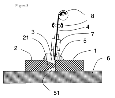
Figure 2 shows an embodiment of the invention wherein a first member (1)
comprising
an aluminium alloy is placed in an abutting relationship with a second member
(2)
having one edge chamfered into a tapered truncated shape (21). The first and
second
members are secured with a schematically represented clamping device (6). In
this
embodiment, the geometry of the abutting relationship (3) is a double-bevel
butt with
broad root face. A MIG torch (7) having a consumable filler wire (4) as
electrode emits
an inert gas which envelops the area of joining and provides the atmosphere
(5) of inert
gas, preventing oxidation of the surface areas adjacent to the abutting parts
of the first
and second members. The back portion of the weld (i.e, the portion of the weld
located
CA 02730028 2011-01-06
WO 2010/003595 6 PCT/EP2009/004828
on the side opposite to the MIG torch) is also protected of oxidation by the
inert gas
(51). Means for providing the consumable electrode (8) are also present in
this
embodiment. The surface of the members is heated to a temperature above the
melting
temperature of the aluminium alloy and below the melting temperature of the
titanium
alloy to obtain a weld-brazed joint.
According to the present invention the chamfered edge of the second member
comprising a titanium alloy must have a specific shape. Figure 3 and Figure 4
are two
examples of specific shapes of the chamfered edge according to the invention.
The
second member has at least one edge with a thickness e. Typically, said second
member
is an extruded profile or a sheet although any edge with a plane-parallel
shape can be of
use. Preferably the first and second members are selected from the group
consisting of
an extruded profile, a sheet and a plate. As shown by Figures 3 and 4, the
edge with a
plane-parallel shape of thickness e has on a first side a first tapering angle
al between
the bevelled portion and the surface said first side, on a second side a
second tapering
angle a2 between the bevelled portion and the surface said second side, and a
minimum
thickness t wherein the sum of al and a2 is between 10 and 50 and t is
between 0.05 e
and 0.3 e. The tapered truncated shape of the invention provides a significant
strength
improvement of the welded joint and an improved process output. If the sum of
al and
a2 is less than 10 , the tapered shape is too sharp compared to the edge
thickness and
the tapered face may not be entirely covered by the weld, which may cause loss
of
strength of the welded joint. If the sum of a1 and a2 is more than 50 , the
tapered shape
is not sharp enough compared to regular square butt geometry, and it does not
provide a
significant strength improvement. If t is lower than 0.05 e, the truncated
shape tip is too
sharp and it may melt during weld-brazing, which should be avoided. If t is
higher than
0.3 e, the truncated shape tip is not sharp enough compared to regular square
butt
geometry, and it does not provide a significant strength improvement.
Preferably the
sum a1 + a2 is between 20 and 40 and/or t is between 0.1 e and 0.2 e.
Although the present inventors are not bound to any specific theory, they
believe that
the improved strength of the weld-brazed joint according to the present
invention is
related to the increase of contact surface between aluminium and titanium
alloys and/or
to the improved flow of the melted alloy aluminium on the titanium alloy
surface and/or
to the absence of sharp contact angles between aluminium and titanium alloys,
in
relation to the tapered truncated shape. The tapered truncated shape is
selected even for
CA 02730028 2011-01-06
WO 2010/003595 7 PCT/EP2009/004828
an edge thickness of less than 2,5 mm contrarily to the usual purpose of
chamfered
edges which is to reduce the thickness of the weld-brazing area.
The first member and the chamfered edge of said second member (21) are then
placed
in an abutting relationship defining a geometry to be weld-brazed. The
abutting
relationship comprises geometries wherein a limited joint spacing is left
between the
members to be weld brazed, typically less than 10% of the second member edge
thickness e. Preferably, said geometry is selected in the group comprising a
bevel butt
with broad root face, a V butt with broad root face, a J- butt, a U-butt and
combination
thereof. By combination it is meant that, for example, a V butt with broad
root face may
be selected on one side whereas a bevel butt with broad root face is selected
on the other
side, providing a V-bevel butt with broad root face geometry.
In an embodiment of the invention, said geometry is a single-bevel butt with
broad root
face having an angle 8 and a depth d, said angle S being between 40 and 80
and
preferably between 50 and 70 , and said depth d being between 70% and 95% and
preferably between 80% and 90% of said second member thickness.. This
embodiment
is illustrated by Figure 5c.
In a preferred embodiment of the invention said geometry is a double-bevel
butt with
broad root face having a first groove on one side with a first angle 81 and a
first depth
dl and a second groove on the other side with a second angle 62 and a second
depth d2
and wherein said first and second angle 61 and 82 are between 40 and 80 and
preferably between 50 and 70 , and wherein the sum of said first depth dl and
said
second depth d2 is between 70% and 95% and preferably between 80% and 90% of
said
second member thickness. This embodiment is illustrated by Figures 5a, 5b, 5d
and 5f.
In another embodiment of the invention, said geometry is a single-V butt with
broad
root face having an angle 8 and a depth d and wherein said angle 8 is between
100 and
140 and preferably between 110 and 130 , and wherein said depth d is
between 70%
and 95% and preferably between 80% and 90% of said second member thickness.
In yet another embodiment of the invention, said geometry is a V- bevel butt
with broad
root face having a first V groove on one side with a first angle 81 and a
first depth dl
and a second bevel groove on the other side with a second angle 82 and a
second depth
d2, wherein said first angle 81 is between 100 and 140 and preferably
between 110
and 130 , wherein said second angle 82 is between 40 and 80 and preferably
between
50 and 70 , and wherein the sum of said first depth and said second depth is
between
70% and 95% and preferably between 80% and 90% of said second member
thickness.
CA 02730028 2011-01-06
WO 2010/003595 8 PCT/EP2009/004828
This embodiment is illustrated by Figure 5e. V butt with broad root shape
geometries on
at least one side are advantageous when the aluminium alloy first member is
too thick to
be melted throughout its entire thickness in usual fusion welding conditions,
typically
this embodiment may be of use when the thickness of the first member is higher
than
2,5 mm or even 5 mm.
Figure 6a and 6b illustrate weld brazed assemblies between extruded profile
sections
made of a titanium alloy (2) and of an aluminium alloy (1) joined by a weld-
braze joint
(10) according to the invention.
When the weld-brazed assembly includes several aluminium alloys members as
illustrated in Figure 6b, an unsymmetrical joint geometry such as for example
single-
bevel geometry (Figure 5c) or unsymmetrical double bevel geometry (Figure 5d)
or
single V geometry, is advantageous. On the other hand, symmetrical geometries
such as
for example double bevel geometry or double V geometry are advantageous for
weld
brazed assemblies including a single aluminium alloy member such as
illustrated in
Figure 6a.
The surface areas of said members adjacent the abutment are then heated to a
temperature above the melting temperature of said aluminium alloy and below
the
melting temperature of said titanium alloy, in the presence of an inert gas
(5) and of a
filler metal (4) to obtain a weld-brazed joint. This operation is herein
referred to as the
weld-brazing step.
Fusion welding processes, such as resistance spot welding, flash butt welding,
laser
welding, arc welding such as TIG (Tungsten Inert Gas) or MIG (Metal Inert
Gas),
plasma welding, electron-beam welding and combinations thereof are preferred
methods used for heating the surfaces of said members. In a preferred
embodiment of
the invention, an arc welding process with a consumable electrode is used. The
advantage of the consumable electrode over the non-consumable electrode are in
particular a reduced heat input which reduces the width if the heat affected
zone and an
easier process automation which enables a higher process output. According to
the
invention process, use of a filler metal is necessary to avoid hot cracks in
the weld.
Various filler metals made of aluminium alloys or zinc alloys are suitable for
the
present invention, the filler metal is usually selected to be compatible with
the first
member aluminium alloy. Examples of filler alloys are 2319, 4043, 4047, 4145,
5087
and 5183. Examples of inert gas suitable for the instant process are argon,
helium,
nitrogen and mixtures thereof. An oxidising gas such as oxygen or carbon-
dioxide may
CA 02730028 2011-01-06
WO 2010/003595 9 PCT/EP2009/004828
be added to the inert gas. A suitable mixture is one that contains at least
95% of argon
or helium and up to 5% of oxygen or carbon dioxide.
Any fusion weldable aluminium alloy can be of use for the process of the
present
invention. In particular, fusion weldable alloys of the 2XXX, 5XXX, 6XXX and
7XXX
series are advantageous. Preferably the aluminium alloy first member is a heat
treatable
alloy, which means that it can be hardened by solution heat treatment and
quenching.
Among heat treatable aluminium alloys, 6XXX alloys or 2XXX alloys having at
least
0.8 wt.% lithium are preferred. Weldable aluminium-lithium alloys having at
least 0.8
wt.% lithium and further containing at least 0.1 wt.% silver ("Weldalte
alloys") are
particularly suitable for the process of the present invention.
For artificially aged aluminium alloy products, the weld-brazing operation may
be
carried out before or after artificial aging. Strength is further improved
when artificial
aging is carried on the weld brazed assembly. In an embodiment of the present
invention said first member is in a T3X or T4X temper during the weld-brazing
step and
the process comprises a step following the weld-brazing step consisting of
aging the
first member to a T6X or T8X temper. However, this additional process step may
not be
advantageous for the process output in some instances, in particular when the
assembly
has large dimensions, such as length of several meters. A weld-brazed assembly
according to the invention is obtainable according a process of the invention
andcomprises a first member (1) comprising a fusion weldable alloy from 2XXX,
5XXX, 6XXX or 7XXX alloy families and a second member (2) comprising a
titanium
alloy and having at least one edge with a thickness e and a tapered truncated
shape
having on a first side a first tapering angle al between the bevelled portion
and the
surface of said first side, on a second side a second tapering angle a2
between the
bevelled portion and the surface of said second side and a minimum thickness
t, wherein
al and a2 are greater than or equal to zero, the sum of al and a2 is between
10 and 50
and t is between 0.05 e and 0.3 e.
A weld-brazed assembly according to the invention has preferentially an
ultimate tensile
strength higher than 260 MPa, and preferably higher than 280 MPa. The weld-
brazed
assembly according the invention can be used for the fabrication of structural
elements
for the aerospace industry. For example, an aircraft seat track comprising a
weld-brazed
assembly according to the invention is advantageous.
Another improvement related to the instant process is a reduction of the width
of the
heat affected zone, which is typically lower than 15 mm or even lower than 10
mm.
CA 02730028 2011-01-06
WO 2010/003595 10 PCT/EP2009/004828
The process according to the present invention enables the use of high welding
speed of
preferably at least 0.5 m/min and even at least 1.0 m/min.
Usually, the finished weld brazed assembly is obtained after two welding runs
: one on
each side of the abutting members, which reduces the process output. The
present
inventors found that with a specific clamping device, it is possible to obtain
a finished
weld brazed assembly with a single welding run, which is highly advantageous
for
process output. Weld-brazing on one side is also advantageous when one side
has low
accessibility, such as in the geometry of Figure 6b. According to an
advantageous
embodiment of the invention, the first and second members are fixed with a
clamping
device comprising means for maintaining a back pressure of inert gas above
atmospheric pressure, preferably higher than 110 kPa or 120 kPa and it is then
possible
to obtain a finished weld-brazed assembly after a single welding run. The back
pressure
of inert gas is the pressure of inert gas around the back portion of the weld.
Unexpectedly, the pressure control obtained with the clamping device according
to the
invention enables to control the aluminium alloy melt flow and in particular
to force the
aluminium alloy melt onto the titanium alloy member, avoiding for example drop
falling or excessive weld collar, during weld-brazing and obtain a
substantially
symmetrical weld brazed joint after a welding run on a single face, whatever
the groove
geometry.
An appropriate clamping device for the process of the invention with means to
control
the inert gas back pressure is now described (Figure 7). The clamping device
(6) useful
for weld-brazing a first member comprising an aluminium alloy (1) to a second
member
comprising a titanium alloy (2), comprises an upper face (66) adapted to press
against
said members to be weld-brazed together, a channel (63), means (641), (642),
(643) for
tightening said members onto said upper face in order to obtain a
substantially leak free
pipe having said channel and members for walls, means (61) for introducing a
gas (52)
into said pipe and means (62) for obtaining a pressure of said gas in said
pipe above
atmospheric pressure so that said pressure forces the aluminium alloy melt
onto said
second member during weld-brazing. The means for tightening the member (1) and
(2)
onto the upper surface (66) are preferably channels (641) linked to a vacuum
pump
(643) through machined tubes (642). Mechanical clamping may also be used but
it
appeared to the present inventors that it is more difficult with this type of
tightening
means to obtain a substantially leak-free pipe between the channel and the
members to
be welded. By substantially leak free it is meant that it is possible to
obtain a pressure
CA 02730028 2011-01-06
WO 2010/003595 11 PCT/EP2009/004828
within the pipe above atmospheric pressure without excessive inert gas input
pressure.
A diffuser may be used advantageously as a mean for obtaining an over
pressure.
The process according to the invention finds many uses, in particular in the
mechanical
construction of transportation vehicles in the car, railway, aerospace,
shipbuilding
industries. Fabrication of structural elements for the aerospace industry is a
preferred
application. The term "structural element" refers to an element used in a
mechanical
construction for which the static and/or dynamic mechanical characteristics
are
particularly important for performance and integrity of the structure, and for
which a
structural calculation is usually required or performed. It is typically a
mechanical part,
which if it fails will endanger the safety of the said construction, its
users, passengers or
others. For an aircraft, these structural elements include particularly
elements making up
the fuselage, such as the fuselage skin, stiffeners or stringers, bulkheads,
circumferential
frames, wings (such as the wing skin), stiffeners, ribs and spars, and the
tail fin
composed particularly of horizontal or vertical stabilisers, and floor beams,
seat tracks
and doors.
Extruded profiles weld brazed with a process according to the invention are
particularly
useful to make aircraft seat tracks.
EXAMPLES
Welded assemblies were prepared comprising 1.8 or 2 mm thick sheets made of an
aluminium alloy and of a titanium alloy having the same thickness. The
titanium alloy
was Ti-6A1-4V. The aluminium alloy was either AA6X56 or AA2X98. AA6X56 was
welded either in the T3X temper or in the T6X temper. When AA6X56 was welded
in
the T3X temper, the welded assembly was aged in order to obtain a T6X temper
after
welding. AA2X98 was welded either in the T3X temper or in the T8X temper. When
AA2X98 was aged in the T3X temper, the welded assembly was aged in order to
obtain
a T8X temper after welding This process is referred to as PWHT (Post Welding
Heat
Treatment) whereas process wherein welding is carried out on an aged aluminium
alloy
member are referred to as HTBW (Heat treatment Before Welding).
MIG arc welding was used as a welding method. The trials were conducted with a
CMT welding machine from Fronius. Argon was used as an inert gas for welding.
The
filler metal was a 4043 alloy wire with a diameter of 1.2 mm. Unless otherwise
CA 02730028 2011-01-06
WO 2010/003595 12 PCT/EP2009/004828
mentioned the titanium sheet was chamfered with the geometry al = a2 = 15 and
t/e =
0,15 ((xl, a2 , t and e as defined in Figure 3). Unless otherwise mentioned
the
aluminium sheet and the chamfered edge of the titanium sheet were placed in an
abutting relationship defining a double bevel butt with broad face geometry.
Two
clamping devices were used. Clamping device A is a standard clamping device
described in Figure 2 and clamping device B is described in Figure 7. When
clamping
device B was used, weld-brazing was carried out only on one side of the
abutting
members. When clamping device A was used, welding was carried out on one side,
then
the welded assembly was turned upside down and welding was carried out in the
other
side. The trial conditions and mechanical properties of the welded joints are
provided in
Table 1.
Table 1. Trials conditions and results.
TYS UTS
Trial Aluminium HTBW PWHT Clamping Welding [MPa] [MPa]
number speed (average (average
alloy device
[m/min] values) b values)b
1 6X56 X A 1,0 224 271
2 6X56 x A 1,0 178 257
3 2X98 x B 1,0 337
4 6X56 X B 1,0 257
5 a 6X56 157-
Reference x B 0.6 226
a : no chamfering of the titanium sheet, square butt geometry before weld-
brazing
b : Standard deviation of variants 1-4, 6 and 7 is < 10 MPa. For trial n 5 the
deviation
between the trials was too large (> 27 MPa) to provide a significant average
value,
maximum and minimum values are indicated.
Images of the weld-brazed sample from trial number 1 (two welding run) and
from trial
number 4 (single welding run) are presented in Figures 7a and 7b,
respectively.
Figure 8 is a hardness profile for weld-brazed samples from trial number 2
(HTBW) and
from trial number 1 (PWHT). The hardness profile is useful to determine the
width of
the heat affected zone. For both samples, the width of the heat affected zone
is around
10 mm, lower than 15 mm.
CA 02730028 2011-01-06
WO 2010/003595 13 PCT/EP2009/004828
The comparison of reference trial number 5 with trial according to the
invention (1 to 4,
6 and 7) clearly shows the advantage of the process according to the invention
: the
strength of weld-brazed samples according to the invention is higher and also
exhibits
less deviation compared to reference weld brazed samples. The further
improvement
related to the post welding heat treatment process is observed in particular
by
comparing trial number 1 to trial number 2. Strength obtained with a single
welding run
(clamping device B) are similar than those obtained with two welding runs
(clamping
device A), the process output is thus doubled with clamping device B.