Note: Descriptions are shown in the official language in which they were submitted.
CA 02730054 2011-01-06
WO 2010/004314
PCT/GB2009/050732
1
MARINE CONNECTION SYSTEM AND METHOD
BACKGROUND
This invention relates to a connection system and a connection method
and more particularly, relates to a sub-sea connection system and method
which is adapted to facilitate connection and/or disconnection of a first
body to a second body. The invention finds particular application in
connecting a first body to a second body in an off-shore environment and
is particularly adapted for use in moderate seas.
PRIOR ART
Connecting a marine structure to its mechanical moorings, electrical
power, communication signals and/or fluid transmission is a common
offshore activity. Current methods require connection work to be carried
out either on the deck of a vessel or on the marine structure itself.
This connection activity in particular is sensitive to the weather conditions
and can involve, as in the case of connecting mooring lines, working with
taut lines under large loads. This is potentially dangerous work which
must be carried out using a restrictive range of vessels and equipment,
and a restrictive range of weather conditions, all factors increasing the
expense of a project.
Furthermore the connection process is often a time-consuming one with
each mooring line, electrical power, communications and fluid
transmission cable being separately connected to the structure. This
extends the length of weather window required for connection operations
increasing the likelihood of delays and adding further to the cost.
CA 02730054 2011-01-06
WO 2010/004314
PCT/GB2009/050732
2
In some cases, marine structures are towed to an installation location with
the moorings already connected. In this case, large vessels are used to
pull the anchors of the moorings into place on site.
Alternatively, when the marine structure reaches the required location, a
winch line is connected from the marine structure to the mechanical
mooring to draw the two together for mechanical connection. A winch may
be permanently mounted on the marine structure to facilitate connection
which increases the cost of the equipment required for each connection
process. Alternatively, the winch may be provided on a towing vessel in
which case it must be connected to each of the marine structure and
mechanical mooring before the connection can be made. As mentioned
above, this adversely affects the time taken for the connection process.
The present invention aims to address these problems and in particular
aims to facilitate faster connection between a first body and a second
body, such as for example a marine structure and a sub-sea umbilical or a
floating cable and a mooring system, over a wider range of weather
conditions, with fewer restrictions on the vessel requirements than known
methods.
It is a further aim of the present invention to remove the requirement to
handle taught lines or make complicated connections on deck. This will
significantly improve the safety of such an operation.
SUMMARY OF INVENTION
According to one aspect of the present invention there is provided a
connection system comprising a first latching element mountable on or to
a first body and a second latching element mountable on or to a second
CA 02730054 2011-01-06
WO 2010/004314
PCT/GB2009/050732
3
body, and means for drawing the first latching element and second
latching element together to facilitate connection of the first body to the
second body, said drawing means comprising a buoyant winching system.
Preferably one of said first and second bodies is a marine structure and
the buoyant winching system is mountable on or to said marine structure.
Conveniently the buoyant winching system is removably mountable on or
to said marine structure.
Preferably said drawing means further comprises a winch line attached at
one end to the winch and connectable at the other end to a tether line to
which the second latching element is adapted to be connected.
Advantageously the winch line passes through the latching element of the
first body.
Conveniently axial drive means are provided on the winch for maintaining
correct spooling of the winch line.
Preferably means are provided for towing the first body the towing means
comprising a towing line connected between the first body and a towing
vessel and wherein the towing line is shorter than the winch line such that
when the free end of the winch line is carried on the towing vessel, whilst
the towing line is under tension, there is no tension in the winch line.
CA 02730054 2011-01-06
WO 2010/004314
PCT/GB2009/050732
4
Advantageously the first latching element comprises a socket mounted on
the first body, and the second latching element comprises a plug locatable
within the socket of the first latching element.
Preferably alignment means are provided to enable correct axial and
rotational alignment of the first and second latching elements.
Conveniently the second latching element is provided with buoyancy
means to maintain the second latching element floating in an upright
orientation at a chosen depth.
Preferably the winch is remotely operable.
In some embodiments the latching mechanism between the first and
second latching elements may be remotely operable.
Advantageously the buoyant winching system comprises hoist means
facilitating installation of the buoyant winching system into a preferred
location on said first or second body.
Preferably mechanical locking means are provided between the first and
second latching elements.
Preferably also a further locking means is provided between the first and
second latching elements to avoid an unintentional disconnection of the
first and second latching elements.
Conveniently the winch is provided with a power supply and/or a
communications system which preferably is routed through the first body,
particularly where the first body is a marine structure.
CA 02730054 2011-01-06
WO 2010/004314
PCT/GB2009/050732
Advantageously the power supply of the winch can act as an auxiliary
power source for the first body.
Preferably the first and second bodies include any combination or single
function from the group comprising: an umbilical, for carrying electrical
current, an optical fibre, for carrying an optical signal, a fluid
transmission
and a mechanical mooring.
Conveniently the connection system includes a viewing system.
Preferably the viewing system relays images to an operator controlling the
connection of the first body to the second body.
According to a further aspect of the present invention there is provided a
connection method for connecting a first body carrying a first latching
element to a second body carrying a second latching element, the
connection method comprising the steps of connecting a winch line from a
buoyant winching system through the first latching element to a tether line
attached to the second latching element and operating the winch to draw
the first and second latching elements together to connect the first body to
the second body wherein the connection of the winch line to the tether line
is carried out without tension in the winch line.
Due to the lack of tension in the first line when the connection is made
between the first line and the tether line, the connection can be made in
rougher seas than currently used connection methods and this therefore
increases the weather window within which the connection between the
lines can be made.
Preferably the buoyant winching system is mounted on or to said first
body.
CA 02730054 2016-02-02
6
Preferably the first and second latching elements are mechanically locked
together once they have
been drawn together.
Conveniently the method further comprises the step of disconnecting or
severing the winch line once
the first and second bodies are connected.
Preferably also the method further comprises the step of removing the buoyant
winching system from
the first body.
In another aspect of the invention, it is provided a connection system
comprising:
a first latching element mountable to a first body;
a second latching element mountable to a second body; and
a buoyant winching system for drawing the first latching element and second
latching element
together to facilitate connection of the first body to the second body, which
buoyant winching system
comprises a winch comprising a frame and a buoyancy unit, the frame being
mounted to the
buoyancy unit such that the winch is adapted to be towed to an off-shore
location by a towing vessel;
a winch line attached at one end to the winch of the buoyant winching system
and connectable at
another end to a tether line to which the second latching element is adapted
to be connected;
a towing line connected between the first body and the towing vessel; and
wherein the towing line is shorter than the winch line such that when a free
end of the winch line is
carried on the towing vessel, whilst the towing line is under tension, there
is no tension in the winch
line.
BRIEF DESCRIPTION OF FIGURES
A preferred Embodiment of the Invention will now be described by way of
example only and with
reference to the Figures in which:
Figures la, lb and lc are schematic views illustrating the components of a sub-
sea
connection/disconnection system according to one aspect of the present
invention;
Figure 2a is a perspective view from above of a buoyant winching system of the
connection system of
Figure 1;
Figure 2b is an end view of the buoyant winching system of Figure 2a;
Figure 2c is a side view of the buoyant winching system of Figure 2a;
Figure 3a is a side view of a first element of the latching mechanism of the
connection system of
figure 1;
CA 02730054 2011-01-06
WO 2010/004314
PCT/GB2009/050732
7
Figure 3b is an enlarged detail of the internal features of the first element
of Figure 3a;
Figure 3c is a front view of the first element of Figure 3a;
Figure 3d is a schematic view of a locking mechanism of the first element
of Figure 3a in a locked condition;
Figure 3e is a schematic view of the locking mechanism of the first
element of Figure 3a in an open condition;
Figure 4a is a view from one side of the turret of the connection system of
Figure 1;
Figure 4b is a view from the other side of the turret of Figure 4a;
Figures 5a to 5h illustrate the connection sequence of the connection
system of Figure 1, and
Figures 5i to 5k illustrate the disconnection sequence of the connection
system of Figure 1.
DETAILED DESCRIPTION OF PREFERRED EMBODIMENTS OF THE
INVENTION
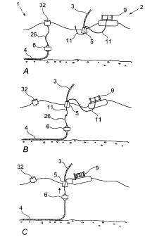
Turning now to the Figures, there is shown in Figure 1 a connection
system 1 according to a first aspect of the present invention. The
connection system comprises a buoyant winching system 2 comprising a
winch 9, which is adapted to be towed to an off-shore location by a tug or
other vessel. A latching mechanism is provided for connecting a first
CA 02730054 2011-01-06
WO 2010/004314
PCT/GB2009/050732
8
cable or body 3 to a second cable or body 4. A first element 5 of the
latching mechanism is mounted on the first cable or body and a second
element 6 of the latching mechanism is connected to the second cable or
body, this element remains permanently located at the connection site.
The buoyant winching system is shown in more detail in figure 2 and in
this embodiment comprises a frame 7 mounted between two buoyancy
units 8, although the frame may be mounted on or to one or more
buoyancy units in other embodiments. In the illustrated embodiment, the
buoyancy units are substantially cylindrical and the frame is mounted
between the long axes of the two buoyancy units. The buoyancy units
may be removably mounted on or to the frame to facilitate storage when
the winching system is in transit and also to allow a damaged unit to be
easily replaced. In a further embodiment, the buoyant winching system or
the winch structure itself may be inherently buoyant.
The winch 9 is carried on the frame. The winch comprises a reel 10 and
one end of a winch line 11 is connected to the reel and the line is wound
around the reel such that it can be selectively paid out and wound in by
rotation of the reel as will be described below. Advantageously, the winch
line is fed on to the reel through a static fairlead and the reel is driven
axially to maintain the correct spooling of the winch onto the reel.
A motor 12 is mounted on the frame and in the preferred embodiment, the
motor is mounted on the winch 9 for rotation and axial drive of the reel 10.
The motor may be powered by a localised power supply mounted on the
frame or alternatively may be powered via an umbilical from a remote
location such as a vessel.
CA 02730054 2011-01-06
WO 2010/004314
PCT/GB2009/050732
9
A yoke may be provided at one end of the frame or first body, preferably
the front end in use, such that the winch line may be selectively guided by
the yoke to prevent fouling of the winch line when the frame is being towed
by a vessel.
A mechanism (not shown) may also be provided for severing or detaching
the winch line once a connection operation is complete.
In the illustrated embodiment of Figure 5, the buoyant winching system 2
is mounted on top of a marine structure 3 which comprises the first body to
be connected to the second body.
In this embodiment the first element 5 of the latching mechanism is
mounted beneath the marine structure and directly below the winch 9
The first element comprises a docking port comprising a receptacle 13 for
receiving a second latching element as will be further described below.
The receptacle has an inner profile 14, which is adapted to assist in
aligning the second latching element both axially and rotationally. The
inner profile may comprise a slot. Means 15 may be provided for
attaching the receptacle to the frame of the buoyant winching system.
The receptacle further comprises a locking system 16 which may be
remotely operated to secure the first and second latching elements
together once the second latching element is docked within the receptacle.
The locking system is shown in detail in Figure 4d and 4e. Figure 4d
illustrates the locking system in an open condition and figure 4e illustrates
the locking system in a closed condition.
CA 02730054 2011-01-06
WO 2010/004314
PCT/GB2009/050732
The locking system comprises a pair of mechanical arms 17 hingedly
mounted on the top of the receptacle. Each arm has a concave recess 18
on the inner edge. The arms are mounted in opposed orientation such
that the concave inner faces form a substantially circular aperture 19 when
the mechanical arms are closed together.
Driving means are provided for operating the arms between an open and a
closed position. In the embodiment shown, the driving means may be a
hydraulic or pneumatic ram 20 mounted between each arm and the body
of the receptacle.
A secondary mechanical locking system 21may also be provided on the
receptacle to provide a failsafe system for use in preventing accidental
unlatching of the second latching element.
The present invention may be provided with a facility (not shown) for
remotely viewing or otherwise obtaining confirmation of successful docking
of a second element of the latching mechanism within the receptacle.
Means (not shown) may also be provided for connecting wiring, hosing or
other umbilicals to and from the marine structure to the receptacle.
Means 36 may also be provided for the automatically connecting and
disconnecting the subsea umbilicals from the second element of the
latching mechanism to the receptacle. This may comprise a wet mate
connector or sub sea plug. Docking of the connectors may take place
during or after the docking operation to be described further below.
A shock absorber 22 is mounted on the body of the receptacle for
absorbing shock loads during the docking process.
CA 02730054 2011-01-06
WO 2010/004314
PCT/GB2009/050732
11
A fairlead 23 is mounted on or adjacent the bottom of the receptacle 13 to
prevent fretting of the winch line during connection operations.
The second element of the latching mechanism is shown in more detail in
Figure 3. The second element comprises a shaped body 24 with a
tapered upper surface 25 which is adapted to be received within the
receptacle 13 of the first element.
An eye bolt (not shown) to enable connection of a tether line 26 may be
provided on the second element, preferably at the top of the shaped body.
A means for establishing a mechanical connection with the first element of
the latching mechanism is provided on the body of the second latching
element. In the embodiment shown, the shaped body has an area of
reduced diameter to form a waist 27, which is shown in this embodiment
as being below the tapered upper surface of the body.
A key 28 and tapered strakes 28' are provided on the side of the body to
align with the inner profile 14 of the receptacle to assist in rotational
alignment of the second element within the receptacle.
The lower part of the body of the second element is provided with means
for mechanically attaching mooring lines. The attachment means in the
illustrated embodiment are apertures 29 through the lower part of the
body.
One or more ports 30 for attaching umbilicals or cables is/are also
provided on the lower part of the body. Means 31 may also be provided
on the body of the second element for connecting and disconnecting
CA 02730054 2011-01-06
WO 2010/004314
PCT/GB2009/050732
12
umbilicals which dock into the ports to the first element of the latching
mechanism. This may comprise an electrical connection or underwater
plug. The connecting and disconnecting means may be remotely
operated from the towing vessel.
The second element of the latching mechanism may be provided with
inherent or inbuilt buoyancy or alternatively one or more buoyancy
modules may be attached to the body of the second element to maintain
the second element at a desired depth, off the seabed but below the
surface when not in use.
The process steps of the preferred method for connecting the first and
second elements of the latching mechanism together are illustrated in
Figure 5 a ¨ 5h.
As shown in Figure 5a, in an initial step, a cable or body 4 is connected to
the second element 6 of the latching mechanism. The cable or body may
be docked in one of the apertures 29 or ports 30 in the lower part of the
body.
The second element 6 of the latching mechanism is connected to a
location buoy 32 using a tether line 26. The location buoy merely
identifies the position of the second element but does not support the
weight of the element. The tether line is fed through the eye-bolt at the top
of the body of the second element using a remotely operated vehicle. The
buoyancy of the second element enables this element to take up a desired
position above the sea bed but below the surface.
In figure 5b, the buoyant winching system 2 is mounted on top of a marine
structure and the first element 5 of the latching mechanism is mounted
CA 02730054 2011-01-06
WO 2010/004314
PCT/GB2009/050732
13
beneath the marine structure, preferably immediately below the reel 10 of
the winch. The winch line 11 is attached to the reel, wound around the
reel and passed through both the marine structure and the receptacle 13
of the first element of the latching mechanism. An I-tube may be provided
through the marine structure which the winch line may pass through.
In the next step as illustrated in Figure 5c, a tow line 33 is connected from
the marine structure 3 to a vessel 34 such as a tug. A second line 35 for
retrieval as will be described below is connected from the buoyant
winching system 2 to the vessel. The winch line 11 is passed from the
floating winch structure to the vessel. The free end of the winch line may
be connected to a fixing point on the vessel. The steps illustrated in
Figures 5b and 5c are preferably carried out at shore or in harbour
although they may also be carried out on a calm day at sea.
The tow line 33 is shorter than the retrieval line 35 and the withdrawn
length of the winch line 11 such that both the winch line and the retrieval
line are slack, the only taut line being the tow line between the vessel and
the frame. The marine structure 3 is maintained at an optimum distance
from the vessel by the tow line to ensure that the winch line and retrieval
line remain slack during the connection operation.
The vessel tows the marine structure 3 to its connection location as
identified by the location buoy 32. The vessel retrieves the location buoy,
removes it and connects the end of the tether line 26 to the end of the
winch line 11 on board the vessel as illustrated in figure 5d.
In the next step as illustrated in Figure 5e, the connected tether line 26
and winch line 11 is thrown overboard. An operator located on the vessel
activates the winch 9 on the marine structure remotely to begin winding
CA 02730054 2011-01-06
WO 2010/004314
PCT/GB2009/050732
14
the tether line and connected winch line on to the reel 10 of the winch and
thereby to pull the second element 6 of the latching mechanism upwards
towards the receptacle 13 of the first element. In the preferred
embodiment, the winch reel is driven axially by the motor 12 to maintain
the correct spooling of the winch line onto the reel.
As the second latching element approaches the receptacle of the first
latching element, the tapered upper surface 25 of the first latching element
enters the receptacle and the key 28 on the body of the second latching
element engages in the inner profile 14 of the receptacle. The axial and
rotation position of the first and second latching elements is therefore
controlled as the elements are drawing together.
Upon docking of the second latching element within the receptacle of the
first latching element, the mechanical arms 17 are operated to encircle the
body of the second latching element in the region of the waisted area 27 of
the body to securely connect the first and second latching elements
together. The secondary locking mechanism is then activated to provide
additional security.
Docking of the shaped body 24 of the second element in the receptacle as
shown in figure 5f is confirmed from the remote viewing system through
proximity. The electrical power, signal and fluid power umbilical
connections are made at the same time.
The winch 9 continues to pull tension on the winch line. Tension is
increased until a weak connector is broken in the line or alternatively the
line is severed.
CA 02730054 2011-01-06
WO 2010/004314
PCT/GB2009/050732
The tow line 33 is then released from the marine structure 3 by a remote
operation carried out by an operator on the vessel (Figure 5g).
The buoyant winching system 2 is pulled off the marine structure 3 using
the winch retrieval line 35 and is recovered to the vessel 33 or alternatively
towed behind the vessel back to shore or harbour where it can be installed
on the next marine structure (Figure 5h and 5f).
Disconnection of the connection system will now be described.
A vessel sails out to the location of the marine structure 3 and a tow line
33 is attached between the vessel and the frame in accordance with a
known method.
An operator on board the vessel remotely actives the latch trigger and the
second element 6 of the latching mechanism is released from the
receptacle 13 of the first element and drops away from the receptacle.
The inherent buoyancy of the second element of the latching mechanism
allows the mechanism to maintain a desired depth above the seabed but
below the surface as described above. The marine structure 3 is then
towed back to shore or harbour (Figure 5k).
It will be apparent to a person of skill in the art that the present invention
provides a connection method and connection system which enables
connection of a first cable or body to a second cable or body using slack
connection lines such that the method and system can be operated in
moderate seas. This considerably widens the weather window within
which the connection method and connection system can be operated.
CA 02730054 2011-01-06
WO 2010/004314
PCT/GB2009/050732
16
Furthermore, by removably mounting the winch upon the floating platform,
the winch may be recovered to the towing vessel once the connection
between the first and second bodies is effected, thereby allowing the
winch to be reused for further connection operations. This reduces the
overall cost of the connection operation by reducing the number of
components required for multiple connection operations.
Additionally, as the connection system of the preset invention can be
operated remotely from a towing vessel, the connection system can be
used in heavier seas and with shorter weather windows than currently
available systems.
Modifications and alterations may be made to the present invention such
as for example, in some embodiments instead of a local motor on the
frame, power may be supplied from a remote vessel via an umbilical
connected to the motor.
In a further embodiment of the present invention, the location buoy may be
attached automatically to the second element of the latching mechanism
upon release of the shaped body from the receptacle.
In a further embodiment of the present invention, the winch structure
and/or buoyant winching system would be provided with means of hoisting
itself, under operator control, to the preferred location on the marine
structure.
Whilst the buoyant winching system and particularly the floating winch has
been described as part of a connection and disconnection system, it is to
be appreciated that the floating winch may be used in other marine
operations where the winch may be temporarily mounted on or to a marine
CA 02730054 2011-01-06
WO 2010/004314
PCT/GB2009/050732
17
structure, operated as required and then removed from the marine
structure. In some cases the winch may be towed or may be driven from
location to location as required.