Note: Descriptions are shown in the official language in which they were submitted.
CA 02730137 2011-01-06
WO 2010/011613 PCT/US2009/051178
1
PORTABLE HYDROSEEDER
CROSS REFERENCE TO RELATED APPLICATIONS
[0001] The present Application claims priority from United States Provisional
Patent
Application No. 61/082,455, filed July 21, 2008, entitled "A spot
hydroseeder/fertilizer that a
typical homeowner can connect to a garden hose for spot seeding for lawn,
slope, ground cover,
flower beds, pastures, herb gardens or virtually any seed that one would like
to propagate. You
may also fertilize any plot of earth by using a granulated or liquid
fertilizer," and from United
States Provisional Patent Application No. 61/208,508, filed February 25, 2009,
entitled "A
hand held spot hydroseeder that a typical homeowner can connect to a garden
hose for spot
seeding for a lawn, slope, ground cover, flower beds, pastures, herb gardens
or virtually any
seed one would like to propagate," the contents of which are incorporated
herein by reference
in their entirety.
FIELD
[0002] The invention pertains to hydro-seeding and more specifically a
hydroseeding
system that is economical, efficient and portable.
BACKGROUND
[0003] Hydroseeding (or hydraulic mulch seeding, hydro-mulching, hydraseeding)
is a
planting process that uses a slurry of seed, fertilizer and mulch. The slurry
is transported in a
housing, either truck-mounted or trailer-mounted and sprayed over prepared
ground in a
uniform layer. Alternatively, helicopters and aircraft can be used where
larger areas must be
covered, such as, for example, burned wilderness areas after a fire.
Hydroseeding is an
alternative to the traditional process of broadcasting or sowing dry seed and
promotes quick
germination and inhibits soil erosion. Hydroseeding is used to seed grass on
commercial sites
(highways/motorways etc.), golf courses, lawns and areas too large,
inaccessible or unsuitable
for conventional methods. Starting a lawn by hydroseeding is considerably
cheaper than laying
sod/turf and quicker than using dry seed. It is also used to spread mixtures
of wildflower and
tree/shrub seeds or turf grasses for erosion control. Hydroseeding typically
has similar costs to
dry seeding techniques that combine seed with straw mulch. Further, the
hydroseeding slurry is
weed free whereas straw mulch can contain weeds. Also, hydroseeding is
typically less than
1/4 the cost of laying sod.
[0004] Disadvantageously, there has never been a portable hydroseeder due to
the pressure
required to eject the mulch. As described in U.S. Pat. No. 3,717,285,
hydroseeding is currently
CA 02730137 2011-01-06
WO 2010/011613 PCT/US2009/051178
2
done by hiring a contractor that has a truck with separate housings for the
water and dry
ingredients (mulch, seed, color etc.) and an agitator pump to mix the water
and the dry
ingredients to produce a slurry that can then be spread over a large area.
United States Pat. No.
4,913,356 describes a portable seeding device that uses suction, using the
venturi effect, to lift a
mixture of water and seed from a jar. The constriction required to lift the
seed and water out of
the jar using the venturi effect is insufficient to allow any mulch to be
added to the jar.
Additionally, the amount of seed and mulch required to cover at least a one
square foot area
would make the jar extremely large and unwieldy.
[0005] Therefore, there is a need for a hydroseeder that is economical,
efficient and
portable that overcomes the problems in the prior art.
SUMMARY
[0006] The problems in the prior art have been successfully overcome by the
present
invention, which is directed to a portable hydroseeding system and method. The
system
comprises a portable housing means for containing a slurry, a propellant means
connected to
the housing and an outlet control means for distributing the slurry. The
propellant means can
be a standard garden hose water connection, a carbon dioxide connection, an
inflatable lining, a
mechanical plunger, a piston, a low pressure air connection, and a high
pressure air connection.
Preferably, the propellant connection is a standard garden hose.
[0007] The housing further comprises an upper housing portion and a lower
housing
portion, an inlet control valve connected to the propellant, a pressure gauge
connected to the
upper housing portion, a jet nozzle internally connected to the upper housing
portion for
spraying the pressurized water into the housing, a lower housing portion
attachable to the upper
housing portion for containing a mixture of dry ingredients to form a slurry,
an exit control
valve for controlling the discharge of slurry from the combined upper housing
portion and the
lower housing portion, and an applicator nozzle connected to the lower housing
portion for
distributing the slurry over an area. In one embodiment, a removable threaded
agitator lid is
connected to the inlet control valve of the housing. An output port is
connected to the housing
and an outlet control valve is connected to the output port to regulate the
distribution of the
slurry. In another embodiment, the outlet control valve further comprises a
slurry supply hose
for ease of use while distributing the slurry. In another embodiment, a second
outlet control
valve attached to the output port is provided for further control of the
pressure in the housing.
[0008] The housing, one or more than one water hose attachments, inlet control
valve,
threaded agitator lid, output port, and second outlet control valve can be
constructed from
CA 02730137 2011-01-06
WO 2010/011613 PCT/US2009/051178
3
wood, plastic, aluminum, steel, fiberglass, carbon fiber, polyethylene, resin,
vinyl, and glass,
but preferably from stainless steel.
[0009] In one embodiment, the lid further comprises an upper water jet
housing, a plurality
of upper water jets, a water shaft, a paddle agitator, and optionally a
plurality of lower water
jets connected to the tank. Optionally, the threaded agitator lid can further
comprise a mixing
shaft for external agitation.
[0010] There is provided a method for using the portable hydroseeding system
comprising
the steps of: a) removing thatch or dead vegetation from one or more than one
areas to be
seeded; b) loosening soil for the one or more than one areas to be seeded; c)
placing the
hydroseeder proximate to one of the one or more than one areas to be seeded;
d) connecting the
hydroseeder to a propellant source; e) opening the hydroseeder; f) adding dry
ingredients to the
hydroseeder; g) closing the hydroseeder; h) opening the inlet valve starting a
flow of propellant
to create a slurry; i) opening the outlet control valve; j) applying the
slurry to the loosened earth
until the housing becomes empty or the slurry is free of seed; and k)
repeating steps c through j
until all areas are seeded.
DRAWINGS
[0011] These and other features, aspects and advantages of the present
invention will
become better understood with regard to the following description, appended
claims, and
accompanying figure where:
[0012] Figure 1A is a schematic diagram of a handheld hydroseeding system that
is
economical, efficient and portable according to one embodiment of the present
invention;
[0013] Figure 1B is a schematic diagram of a piston-driven handheld
hydroseeding system
that is economical, efficient and portable according to another embodiment of
the present
invention;
[0014] Figure 2 is a schematic diagram of a hydroseeding system that is
economical,
efficient and portable according to another embodiment of the present
invention; and
[0015] Figure 3 is a flowchart diagram of some steps of a method for using the
hydroseeder
shown in Figures 1 and 2.
CA 02730137 2011-01-06
WO 2010/011613 PCT/US2009/051178
4
DETAILED DESCRIPTION
[0016] The present invention solves the problems with the prior art by
providing a
hydroseeder that is economically feasible for an individual to own, and is
efficient because in
one embodiment the hydroseeder only requires a regular garden hose to operate
and is portable
so that the individual user can use the hydroseeder anywhere at any time
without the need to
hire a commercial contractor with a massive hydroseeding vehicle as required
by the prior art.
Additionally, a separate agitating pump is not needed, as the present
invention is a portable or
hand held hydroseeder which anyone can use to propagate a slurry of seed,
fertilizer and mulch
using any municipal water source, such as, for example, a garden hose, or
other propellants.
The portable hydroseeder unit is lightweight, compact, reusable and can be
easily stored. The
portable hydroseeder described herein has the capabilities of large commercial
hydroseeders
with compact and portable convenience.
[0017] As used in this disclosure, except where the context requires
otherwise, the term
"comprise" and variations of the term, such as "comprising", "comprises" and
"comprised" are
not intended to exclude other additives, components, integers or steps.
[0018] The term "slurry" refers to a mixture of water, seed and mulch with
other additives,
such as, fertilizer, coloring agent and weed killer or pre-made mixtures, such
as, for example,
Scotts Patchmaster products among others.
[0019] The term "portable" refers to a device that can be transported from
location to
location by no more than two persons and preferably only one person.
[0020] In the following description, specific details are given to provide a
thorough
understanding of the embodiments. However, it will be understood by one of
ordinary skill in
the art that the embodiments can be practiced without these specific details.
For example,
circuits can be shown in block diagrams in order not to obscure the
embodiments in
unnecessary detail. In other instances, well-known circuits, structures and
techniques can be
shown in detail.
[0021] Also, it is noted that the embodiments can be described as a process
that is depicted
as a flowchart, a flow diagram, a structure diagram, or a block diagram.
Although a flowchart
can describe the operations as a sequential process, many of the operations
can be performed in
parallel or concurrently. In addition, the order of the operations can be
rearranged. A process
is terminated when its operations are completed.
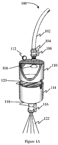
[0022] As can be seen in Figure 1A, there is shown a schematic diagram of a
handheld
hydroseeding system 100 that is economical, efficient and portable according
to one
CA 02730137 2011-01-06
WO 2010/011613 PCT/US2009/051178
embodiment of the present invention. The handheld hydroseeding system 100
comprises a
water hose 102 attachment 104 connected to a water control valve 106. The
water control
valve 106 controls the amount of water provided to a jet nozzle 108 located
inside an upper
housing portion 110. A pressure gauge 112 is also attached to the upper
housing portion 110 so
5 that the user can observe when water pressure inside a combined upper
housing portion 110 and
a lower housing portion 114 is sufficient for operation of the hydroseeding
system 100. An
applicator nozzle 118 is attached to the lower housing portion 114. The upper
housing portion
110 provides space for the incoming water to flow into the lower housing
portion 114
containing a dry mixture 120 of fertilizer, seed and mulch. The upper housing
portion 110 and
the lower housing portion 114 are connected together to form the housing 110
and 114 by any
typical means known in the art, such as, for example, clamps and screw
fittings, to remain
joined while under the pressure applied by the propellant. The jet nozzle 108
forces the water
completely into the dry mixture 120 making a slurry 122. The jet nozzle 108 is
positioned so
that the spray pattern forces all the dry mixture 120 into solution without
leaving any dry
mixture in the combined upper housing portion 110 and lower housing portion
114. The
applicator nozzle 118 can be designed to spray various patterns, such as, for
example, a square
pattern, a round pattern, and rectangular pattern among others as will be
understood by those
with skill in the art with reference to this disclosure. An exit control valve
116 controls the
discharge of the slurry 122 from the combined upper housing portion 110 and
the lower
housing portion 114.
[0023] Figure 1B shows a schematic diagram of a handheld hydroseeding system
100 that
is economical, efficient and portable according to another embodiment of the
present invention.
In this embodiment the elements of the hydroseeder described in Figure 1A are
identical with
the exception of a plunging means 124 that replaces the jet nozzle 108 shown
in Figure 1A.
The plunging means 124 can comprise various components, such as, for example,
an inflatable
rubber lining that expands to fill the housing 110 and 114, a hydraulic
plunger or a piston
among others that can push the slurry 122 out of the housing 110 and 114 only
using pressure
provided at the water hose attachment 102. Other propellants, such as, for
example, carbon
dioxide cartridges, compressed air cartridges, low pressure air lines, high
pressure air lines,
mechanical ratchet plungers, pistons and gravity flow can be used to
distribute the slurry 122
from the hydroseeder 100 onto the area to be seeded.
[0024] As can be seen in Figure 2, there is shown a schematic diagram of a
portable
hydroseeding system 100 that is economical, efficient and portable according
to another
CA 02730137 2011-01-06
WO 2010/011613 PCT/US2009/051178
6
embodiment of the present invention. The hydroseeding system 200 comprises a
water hose
202 attached to a first inlet control valve 204. The first inlet control valve
204 is connected to a
removable threaded agitator lid 206 and provides water to pressurize housing
208. The lid 206
can be opened to insert a dry mixture of seed, mulch and other additives that
when mixed with
water will become the hydroseeding slurry. The lid 206 further comprises a
plurality of upper
water jets 214 connected to a paddle agitator 224. When inlet control valve
204 is opened,
water will flow through the lid 206 and into the plurality of upper water jets
214. The water
from the upper water jets 214 will convert the dry mixture into the slurry to
be distributed. The
pressure from the incoming water will force the slurry to the output port 210.
The threaded
agitator lid 206 can further comprise a mixing shaft attachment (not shown) so
that a user can
connect a drill to provide agitation via a paddle agitator 224. Optionally,
the hydroseeding
system 200 further comprises a second inlet control valve (not shown) that
supplies propellant
to a set of lower water jets 222. The lower water jets 222 can provide
additional mixing action
to form the slurry and prevent the dry mixture from adhering to the tank 208.
[0025] Once sufficient water has been added, the water and dry ingredients
will form the
slurry and the housing 208 will be pressurized to the maximum amount from the
supplied
propellant so that the slurry can be forced out of the output port 210 to be
distributed over an
area to be seeded using only the pressure in the housing and the water
pressure from the water
hose 202. An outlet control valve 212 regulates the distribution of the slurry
from the housing
208 to the area to be seeded. As can be appreciated, the outlet control valve
212 can be
attached to a slurry supply hose 220 for ease of use. Optionally, a second
outlet control valve
can be attached to the output port 210 for further control of the pressure in
the housing 208. It
should further be noted that the lid 206, the housing 208 and the other
elements that comprise
the device can be made of various materials, such as, for example, wood,
plastic, aluminum,
steel, fiberglass, carbon fiber, polyethylene, resin, vinyl, glass, or any
other sufficiently resilient
material that can maintain the slurry under pressure. However, stainless steel
is preferable due
to its non-corrosive properties and ease of cleaning.
As can be appreciated, there are many possible variations. Among the
variations
contemplated include a cartridge system, where the dry mixture is present with
the proper ratio
of seed, mulch, fertilizer and other additives and is only used once.
Additionally, a cartridge
system comprising a premixed slurry and a non-water propellant, such as, for
example, carbon
dioxide(C02)or a compressed air canister is also contemplated for a portable
system that does
not require a water hose connection. The most basic form for a portable
hydroseeding system
CA 02730137 2011-01-06
WO 2010/011613 PCT/US2009/051178
7
comprises a housing for containing a slurry, a pressurizing propellant
connected to the housing
and an outlet control mechanism for distributing the slurry.
[0026] Referring now to Figure 3, there is shown some steps 300 of a method
for using the
hydroseeder 100 or 200. First, thatch or dead vegetation is removed 302 from
one or more
than one areas to be seeded. Then, soil for the one or more than one areas to
be seeded, is
loosened 304 to provide better seed adhesion. Next, the hydroseeder 100 or 200
is placed 306
proximate to the area to be hydroseeded. Then, the hydroseeder 100 or 200 is
connected to a
pressurized water source 308 using a hose 102 or 202. Next, an optional slurry
supply hose 220
is connected to the output 118 or 212 on the hydroseeder 100 or 200. Then,
inlet valve 106 or
204 is opened starting a flow of pressurized water. Optionally, a second water
hose can be
connected 310 to the hydroseeder to provide a second source of water to insure
complete
mixing of dry ingredients into a slurry and to assist in pressurizing the
hydroseeder. Next, the
hydroseeder 100 or 200 is filled with water to 1/2 capacity 312 to prime the
hydroseeder 100 or
200 for operation. Then, dry ingredients, such as, for example, seed,
cellulose mulch and
granulated or liquid pre-plant fertilizer are added 314 to the hydroseeder 100
or 200 to 3/4
capacity. Next, the hydroseeder 100 or 200 is securely closed 316. Optionally,
a drill can be
temporarily connected to the hydroseeder 200 to mix the dry ingredients 318
with the water for
30-60 seconds. Then, the user opens the outlet control valve and applies the
slurry 320 to the
earth until the housing becomes empty or the slurry is free of seed. Repeat
the steps 322 until
all areas are seeded.
[0027] Although the present invention has been discussed in considerable
detail with
reference to certain preferred embodiments, other embodiments are possible.
Therefore, the
scope of the appended claims should not be limited to the description of
preferred embodiments
contained in this disclosure. All references cited herein are incorporated by
reference in their
entirety.