Note: Descriptions are shown in the official language in which they were submitted.
CA 02730353 2011-02-04
- 76452-27D
Public Access CPR and AED Device
Related Applications
This application is a divisional application of Canadian
Patent Application No. 2,364,134 and claims priority from therein.
Field of the Invention
This invention relates to the resuscitation of cardiac
arrest victims.
Background of the Invention
Cardiopulmonary resuscitation (CPR) is a well known and
valuable method of first aid. CPR is used to resuscitate
people who have suffered from cardiac arrest after heart
attack, electric shock, chest injury and many other causes.
During cardiac arrest, the heart stops pumping blood, and a
person suffering cardiac arrest will soon suffer brain damage
from lack of blood supply to the brain. Thus, CPR requires
repetitive chest compression to squeeze the heart and the
thoracic cavity to pump blood through the body. Very often,
the victim is not breathing, and mouth to mouth artificial
respiration or a bag valve mask is used to supply air to the
lungs while the chest compression pumps blood through the
body. The methods of providing oxygenated airflow to the
lungs are referred to as ventilation.
=
It has been widely noted that CPR and chest compression
can save cardiac arrest victims, especially when applied
immediately after cardiac arrest. Chest compression requires
that the person providing chest compression repetitively push
down on the sternum of the victim at 80-100 compressions per
minute. CPR and closed chest compression can be used
CA 02730353 2011-02-04
=
76452-27D
anywhere, wherever the cardiac arrest victim is stricken. In the field, away
from
the hospital, CPR may be accomplished by ill-trained bystanders or highly
trained
paramedics and ambulance personnel.
When a first aid provider performs chest compression well, blood
flow in the body is typically about 25-30% of normal blood flow. This is
enough
blood flow to prevent brain damage. However, when chest compression is
required for long periods of time, it is difficult if not impossible to
maintain
adequate compression of the heart and rib cage. Even experienced paramedics
cannot maintain adequate chest compression for more than a few minutes.
Hightower, et al., Decay In Quality Of Chest Compressions Overtime, 26 Ann.
Emerg. Med. 300 (Sep. 1995). Thus, long periods of CPR, when required, are not
often successful at sustaining or reviving the victim. At the same time, it
appears
that, if chest compression could be adequately maintained, cardiac arrest
victims
could be sustained for extended periods of time. Occasional reports of
extended
CPR efforts (45-90 minutes) have been reported, with the victims eventually
being
saved by coronary bypass surgery. See Tovar, et al., Successful Myocardial
Revascularization and Neurologic Recovery, 22 Texas Heart J. 271 (1995).
In efforts to provide better blood flow and increase the effectiveness
of bystander resuscitation efforts, chest compression devices capable of
performing the tasks of the basic CPR procedure have been proposed and used.
Our own modular CPR device, described in U.S. Patent Nos. 6,142,962 and
6,066,106 provide for circumferential chest compression performed by a battery
operated motor and clutch assembly. The chest compressions are accomplished
automatically after installation and initialization of the system. The devices
are
designed for use by both untrained and trained operators, so that they may be
used on patients as quickly as possible. It is intended that any bystander
recognizing a fallen patient will be able to gain access to a nearby device,
install
the device, and initiate the operation of the device to commence chest
compression and patient monitoring.
2
CA 02730353 2011-10-12
76452-27D
Our CPR devices described in U.S. Patent Nos. 6,142,962 and
6,066,106 also incorporate an automatic emergency defibrillator.
Defibrillation is a
well known technique for restoring normal heart rhythm to a patient who is in
cardiac
arrest due to ventricular fibrillation or ventricular tachycardia. It involves
attaching
electrodes to the patient and applying a large electrical shock to the
patient.
Defibrillation can resuscitate a large class of cardiac arrest patients, and
its success
is enhanced by application of the shock early in the resuscitation effort. A
minute or
so of chest compression also enhances the effectiveness of defibrillation
shocks in
reviving the patient.
Recently, automatic emergency defibrillators (AED) have been installed
in controlled areas such as airplanes, where the presence of trained operators
and
secure access to the AED can be maintained. The practice of installing AED's
in
controlled areas is sometimes referred to as Public Access Defibrillation.
However,
laws in most jurisdictions forbid installation of the devices without
maintenance of a
number of trained operators in the controlled area and oversight of the
program
maintenance by a doctor.
U.S. Patent No. 6,213,960 provides a control system for operating an
automatic defibrillator and an automatic chest compression device in
coordination
with each other to enhance the effectiveness of the resuscitation. The device
also
provides electro-stimulation for electroventilation, electro-counterpulsion,
abdominal
binding and glottic closure, all coordinated with the chest compression device
to
effect electro-stimulation at various points in the compression cycle.
Summary
The public access CPR and AED device described below is intended to
be installed in public areas where access is readily available to bystanders,
first
responders, emergency medical technicians (EMT's) and doctors. However, it is
not
necessary, nor desirable, to permit full access of the device to the entire
range of
people who might desire or require access since some users will not be
properly
trained to supervise the device's operation. To control and thus permit the
optimal
3
CA 02730353 2011-10-12
76452-27D
degree of access to the system, a tiered access system is used to control
physical
access and functional enablement of the system. Physical access means access
to
the device itself, and/or access to certain accessories used for patient
treatment in
conjunction with the device that may be stored in the device or with the
device
(endotracheal (ET) tubes, venous access kits, laryngoscopes, drugs, etc.).
Functional enablement refers to the system allowing operation of certain
functions,
such as chest compression, alteration of setpoints, application of
defibrillating shock,
etc. Thus, the system must be told (or determine for itself) that it is
permitted to
initiate a therapeutic mode before it does so. One mechanism for
differentiating the
type of user accessing the device is through the identification subsystem
sensors,
since, for example, only trained personnel are "key holders".
The intended models of use for these systems include installation in
hospitals and ambulances, and widespread installation in public areas such as
workplaces, shopping centers, athletic facilities and stadiums, and even in
homes of
patients with an identified high risk of cardiac arrest. The devices may be
installed in
hospitals and ambulances without concern about the level of training for the
expected
user, because the expected user will be a highly trained operator such as a
physician, nurse or emergency medical technician. These trained users can be
expected or required to have the expertise necessary to supervise and
administer all
phases of the resuscitation protocol. However, because installation and
activation
within minutes of the onset of cardiac arrest is critical to saving a
patient's life, it is
desirable to allow the device to be deployed by untrained bystanders or
minimally
trained first responders, and permit trained first responders and untrained
bystanders
to operate the device in safe modes. The system reserves physical access to
advanced equipment and/or functional enablement of advanced modes which may
present some danger to the patient for trained first responders. The system
may
have additional treatment modules, such as drug delivery equipment, that
should only
be used by expert operators, and the system prohibits access to these modules
to all
but identified expert operators. Trained first responders and expert operators
may
identify themselves
4
CA 02730353 2011-02-04
76452-27D
to the system through the use of access cards, identification numbers or
access
codes, while the system may assume lack of identification indicates use by an
untrained bystander. In all instances of use, the system initiates
communications
with a remote medical center, wherein operator identity may be confirmed and
the
level of access and enablement of the system may be adjusted remotely.
Some embodiments disclosed herein relate to a medical system for
use on a patient, wherein said medical system requires an operator for use
upon
the patient, the operator having an operator's predetermined permitted level
of
access, said medical system comprising; a chest compression device for
compressing the chest of the patient and a defibrillator for providing
defibrillating
shock to the patient, wherein both the chest compression device and the
defibrillator are capable of being either functionally enabled or functionally
disabled depending upon the operator's predetermined permitted level of
access;
an identification means for identifying an operator of the system, said
identification
means comprising an identification card and a card reader, wherein said
identification card stores identification information pertaining to the
operator's
predetermined permitted level of access; controlling means for controlling the
chest compression device and the defibrillator in response to the indication
of the
operators permitted level of access as read from the identification card.
Some embodiments disclosed herein relate to a medical system for
use on a patient, wherein said medical system requires an operator for use
upon
the patient, said medical system comprising; a chest compression device for
compressing the chest of the patient and a defibrillator for providing
defibrillating
shock to the patient, wherein both the chest compression device and the
defibrillator are capable of being either functionally enabled or functionally
disabled depending upon the operator's predetermined permitted level of
access;
an identification means for identifying an operator of the system, said
identification
means comprising an identification card and a card reader, wherein said
identification card stores identification information pertaining to the
operator, an
indication of the operators permitted level of access, and authentication
information for the operator and; means for entering authentication
information
5
CA 02730353 2011-02-04
76452-27D
into the identification means for comparison with the authentication
information
stored on the identification card; controlling means for controlling the
plurality of
resuscitation means in response to the indication of the operators permitted
level
of access as read from the identification card, the controlling means
comprising
means for limiting functional enablement of at least one of the plurality of
the
resuscitation means while permitting functional enablement of at least one
other of
the plurality of resuscitation means.
Some embodiments disclosed herein relate to a resuscitation system
for use on a patient, wherein said resuscitation system requires an operator
for
deployment on the patient, said resuscitation system comprising; a chest
compression device for compressing the chest of the patient and a
defibrillator for
providing defibrillating shock to the patient, wherein both the chest
compression
device and the defibrillator are capable of being either functionally enabled
or
functionally disabled depending upon the operator's predetermined permitted
level
of access; an identification means for identifying an operator of the system,
said
identification means comprising an identification card and a card reader,
wherein
said identification card stores identification information pertaining to the
operator,
and an indication of the operators permitted level of access; and means for
entering authentication information into the identification means for
comparison
with the authentication information stored on the identification card;
controlling
means for controlling the plurality of resuscitation means in response to the
indication of the operators permitted level of access as read from the
identification
card, the controlling means comprise means for limiting functional enablement
of
at least one of the resuscitation means while permitting functional enablement
of
at least one other of the plurality of resuscitation means.
Some embodiments disclosed herein relate to a resuscitation system
for use on a patient, wherein said resuscitation system requires an operator
for
deployment on the patient, said resuscitation system comprising; sensing means
for sensing a biological parameter of the patient; a chest compression device
for
compressing the chest of the patient and a defibrillator for providing
defibrillating
shock to the patient, wherein both the chest compression device and the
6
CA 02730353 2011-10-12
76452-27D
defibrillator are capable of being either functionally enabled or functionally
disabled
depending upon the operator's predetermined permitted level of access; an
identification means for identifying an operator of the system, said
identification
means comprising an identification card and a card reader, wherein said
identification
card stores identification information pertaining to the operator, an
indication of the
operators permitted level of access, and authentication information for the
operator;
and means for entering authentication information into the identification
means for
comparison with the authentication information stored on the identification
card;
controlling means for controlling the plurality of resuscitation means in
response to
the indication of the operators permitted level of access as read from the
identification
card, the controlling means comprising means for limiting functional
enablement of at
least one of the plurality of resuscitation means while permitting functional
enablement of at least one other of the plurality of resuscitation means.
Some embodiments disclosed herein relate to a medical treatment
system for treatment of a patient wherein the medical treatment system is
removed
from a secure storage device and deployed upon the patient by a first operator
pending arrival of a second operator, said medical treatment system
comprising; a
plurality of medical devices; means for controlling physical access to the
plurality of
medical devices; means for controlling functional enablement of a first
medical device
included within the plurality of medical devices; means for identifying the
first operator
and permitting physical access to the first medical device by the first
operator; means
for identifying the second operator and permitting functional enablement of
the first
medical device included within the plurality of medical devices upon
identification of
the second operator; wherein the means for controlling physical access is
operable to
permit physical access to the first medical device included within the
plurality of
medical devices depending upon the identity of the first operator; and the
means for
controlling functional enablement is operable to permit functional enablement
of the
first medical device included within the plurality of medical devices
depending upon
the identity of the second operator.
6a
CA 02730353 2014-03-12
76452-27D
Some embodiments disclosed herein relate to a medical treatment
system for treatment of a patient wherein the medical treatment system is
removed
from a secure storage device and deployed upon the patient by any one of a
number
of potential operators, said medical treatment system comprising; a plurality
of
medical devices; means for controlling physical access to the plurality of
medical
devices; means for controlling functional enablement of a first medical device
included within the plurality of medical devices; means for identifying a
particular
operator attempting to use the medical treatment system as a first operator
and
permitting physical access to the first medical device by the first operator;
means for
identifying another particular operator attempting to use the medical
treatment system
as a second operator and permitting functional enablement of the first medical
device
included within the plurality of medical devices upon identification of the
second
operator; wherein the means for controlling physical access is operable to
permit
physical access to the first medical device included within the plurality of
medical
devices depending upon the identity of the first operator; and the means for
controlling function enablement is operable to permit functional enablement of
the
first medical device included within the plurality of medical devices
depending upon
the identity of the second operator.
Some embodiments disclosed herein relate to a system for use on a
patient, wherein said system requires an operator for deployment on the
patient, and
the system may be operated by various classes of operators assigned varying
levels
of access, said system comprising: a chest compression device; defibrillation
electrodes for supplying a defibrillating shock to the patient; identification
means for
determining the level of access of an operator of the system; and a computer
operably connected to the identification means, said computer programmed to
permit
the compression device to be placed on the patient and permit operation of the
compression device when the compression device is placed on the patient
regardless
of the operator's permitted level of access; wherein the computer is further
programmed to prohibit delivery of a shock through the defibrillation
electrodes for
operators having a first permitted level of access and to allow delivery of a
shock
6b
CA 02730353 2014-03-12
76452-27D
through the defibrillation electrodes for operators having a second permitted
level of
access.
Some embodiments disclosed herein relate to a medical treatment
system for treatment of a patient, wherein said medical treatment system is
intended
to be used in an environment wherein the device may be removed from a secure
storage device and deployed upon the patient by a first operator pending
arrival of a
second operator, said medical treatment system comprising: a plurality of
medical
devices; means for controlling physical access to the plurality of medical
devices;
means for controlling functional enablement of a medical device included
within the
plurality of medical devices; means for determining the level of access of the
first
operator and permitting physical access to a medical device by the first
operator
while prohibiting functional enablement of the medical device to the first
operator;
means for determining the level of access of the second operator and
permitting
functional enablement of a medical device included within the plurality of
medical
devices upon determining the level of access of the second operator; wherein
the
means for controlling physical access is operable to permit physical access to
a
medical device included within the plurality of medical devices depending upon
the
level of access of the first operator; and the means for controlling
functional
enablement is operable to permit functional enablement of a medical device
included
within the plurality of medical devices depending upon the level of access of
the
second operator.
Brief Description of the Drawings
Figure 1 is a diagram of a chest compression, ventilation and
defibrillation device controlled by the tiered access system.
Figure 2 is a block diagram of the system for controlling access to a
resuscitation device.
Figures 3A and 3B show the system flow chart for system of Figure 2,
with details of the tiered access system.
6c
CA 02730353 2014-03-12
,
76452-27D
Figure 4 shows the device of Figure 1 installed in a locked mounting
device.
6d
CA 02730353 2011-10-12
76452-27D
Detailed Description of the Inventions
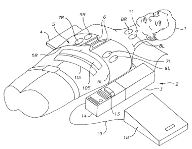
Figure 1 shows the Public Access CPR and AED Device
mounted on a patient 1 and ready for use. The chest
compression subsystem 2 comprises the motor box 3, the belt
cartridge 4, and the compression belt 5 with left and right
portions 5L and 5R. The belt is fastened around the patient
with fasteners 6 (which may be buckles, Velcro lm hook and loop
fasteners or other fasteners with sensors to sense when the
belt is fastened). Ventilation electrodes 7L and 7R are
mounted on the belts in the area of the lower chest and placed
bilaterally over the diaphragm. Bipolar electrodes 8L and 8R
(or electrode pairs) may also be placed on the neck,
bilaterally, to stimulate the phrenic nerve which courses
downwardly through the neck. Defibrillation electrodes 9R and
9L are placed on the right and left sides of the chest and
they may also be located below the patient, on the spine
between the shoulder blades, and on the center of the chest,
respectively. These electrodes are used for establishing the
electrical contact needed for electrocardiogram (EKG) sensing, and also for
defibrillating the patient. Counterpulsion electrodes 10i and
10s are placed on the skin over the abdominal or rectus
muscles, with a line of positive electrodes placed in the
superior position and a line of ground electrodes placed in
the inferior position. Glottic control electrodes are
disposed on an electrode patch 11 placed on the neck along the
tracheo-esophageal groove.
The control box 12 houses a computer system that controls
the various functions of the device. The computer system
7
CA 02730353 2011-02-04
' 76452-27D
controls operation of the chest compression device,
acquisition of signals from various feedback mechanisms such
as the EKG electrodes, and application of stimulating or
defibrillation pulses to the electrodes. (Commercially
available sensors, electrodes and EKG analysis systems such as
the ForeRunnern4 AED sold by HP Heartstream can be used as the
basis for the cardioverting subsystem). The computer system
may also control operation of additional therapeutic modules,
such as drug injection modules. The computer system also
controls the communications subsystem 13 used to initiate and
maintain communication with a remote medical facility. The
communications subsystem may include a telephone handset,
keypad and display.
An identification subsystem 14 is operably connected to
the control box 12 and/or communication subsystem, 13 and may
include a key card reader 15 for reading an encoded card, a
keyboard or touchpad 16 for entry of an access code or
personal identification number, and a biometric sensor 17 for
reading a biometric parameter of the user such as a
fingerprint. A secure device enclosure 18 is connected to the
control box through electronic cable 19, and is locked or
unlocked as controlled by the computer system. The secure
device enclosure may house ventilation equipment such as bag
valve masks or ventilation tubes, medication used in the ACLS
protocol, invasive devices such as intravenous needles (and,
if desired, defibrillation electrodes). The system also
includes diagnostic devices for sensing EKG, pulse,
respiration and temperature. Thus, the system includes
8
CA 02730353 2011-02-04
76452-27D
several means for resuscitation of the patient and several
means for sensing biological parameters of the patient to
diagnose the patient. Any number of medical devices, including
resuscitation devices and diagnostic devices, may be employed
in the system.
The Public Access CPR and AED Device illustrated in
Figure 1 compresses the chest to force blood circulation;
stimulates the patient's nerves to cause an inhaling
contraction of the diaphragm, the intercostal muscles, and the
abdominal muscles; stimulates the patient's abdominal muscles
to cause binding or counterpulsile contraction of the abdomen;
and delivers defibrillating electrical shock to the patient.
The computer system controls all of these therapeutic modes,
subject to initialization and enablement of these actions by
the operator or remote medical center.
The device is intended to be installed in public areas
where access is readily available to bystanders, first
responders, EMT's and doctors. The device should be quickly
installed on a heart attack victim, prior to the arrival of
specially trained users. However, it is not necessary, nor
desirable, to permit full access of the device to the entire
range of people who might desire or require access since some
users will not be properly trained to supervise the device's
operation. To control and thus permit the optimal degree of
access to the system, a tiered access system is used to =
control physical access and functional enablement of the
system. Physical access means access to the device itself,
and/or access to certain accessories used for patient
9
CA 02730353 2011-02-04
s 76452-27D
treatment in conjunction with the device that may be stored in
the device or with the device (ET tubes, venous access kits,
laryngoscopes, drugs, etc.). Functional enablement refers to
the system allowing operation of certain functions, such as
chest compression, alteration of setpoints, application of
defibrillating shock, etc. The system must be told (or
determine for itself) that it is permitted to initiate a
therapeutic mode before it does so. One mechanism for
differentiating the type of user accessing the device is
through the identification subsystem sensors, since, for
example, only trained personnel are "key holders" (as
described in further detail below in reference to Figure 3.)
The system utilizes a remote medical facility (not
shown). The medical facility may maintain a database that
stores user identification information, an indication of the
user's permitted level of access, and the user's
authentication information.
Figure 2 illustrates the overall system functions. The
initialization module 20 waits for user input that indicates
the system is in use and must begin operation. Once the device
is accessed, the initialization module operates to start
several modules. The system establishes communications with a
remote medical facility through the communications module 21.
During use, the system will accept user identification
information, as indicated by the user identification input
module 22. The system analyzes the user's identification,
input from a remote medical facility if available, in the
identification processing module 23. The system utilizes the
CA 02730353 2011-02-04
= 76452-27D
user's identity to determine whether or not a user will be _
allowed physical access to the device, as indicated by the
physical access module 24. The system also uses the user's
identity to determine which of the various capabilities of the
system will be enabled, as indicated by the functional
enablement module 25. The remote input module 26 receives
input from a remote medical facility, and this input can be
used to control the resuscitation devices.
Figures 3A and 3B show the system flow chart for system
of Figure 2, with details of the tiered access system. The
initialization module 20 achieves the system's ready state.
The device is intended to be stored for extended periods of
time before it is used, thus making it impractical to keep the
computerized components fully operational at all times and the
system in constant communication with a remote medical
facility. Thus, whenever the system is used, it must be
started up so that the various subsystems can achieve a ready
state. The system can be designed to start up as any
computerized system, either from a completely un-powered
condition or from a sleep mode, in which the computer control
module is always energized to the extent necessary to sense an
input (comparable to a lap-top computer in sleep mode).
The initialization module monitors the system housing to
sense a unit access attempt. This is also known as an
initiating event, such as the removal of the device from a
storage location, disconnection from a charging battery
holder, insertion of a key card into the card reader, or
operation of any startup sequence initiated by the operator
11
=
CA 02730353 2011-02-04
76452-27D
(pushing a button, entering an access code, etc). Figures 3A
and 3B illustrates an embodiment of the system which uses
insertion of a key card (for trained users) as one initiating
event, and a push button or telephone pick up (for bystanders)
as an alternate initiating event.
Upon recognition of the initiating event, in addition to
the steps taken in the CPR protocol as illustrated in our
prior patents, the initialization module establishes a
communication link with a remote medical facility. Via this
link, the initialization module communicates the activation
attempt to the medical facility, and differentiates to the
medical facility the type of initiating event (physical
removal of the device versus insertion of a key card). In
this way, the medical facility is made aware of the device
activation as well as the type of user activating the device.
The initialization module also communicates an encrypted
device ID to the remote medical facility such that the remote
medical facility will know where to send trained EMTs. The
initialization module also optionally activates an associated
video camera system.
The user identification module 22 seeks input from the
identification subsystem 14. The identification subsystem may
include a key card reader 15, an access code system (touchpad)
16, or mechanical key system (not shown). In this manner,
operators of different training levels may be issued a key
card, security code, or actual key, so that these trained
operators can identify themselves to the system as "key
12
CA 02730353 2011-02-04
= 76452-27D
holders". Several levels of access may be provided by use of
several "keys," each issued to different levels of trained
users and each accepted by the system as identification of a
different level of trained user. This provides for the
-tiered" access system.
The identification subsystem 14 may also include an
optional biometric sensor 17 for use in coordination with a
key card reader, using both the biometric information on the
key card and the sensed biometric information to ensure the
user's identity, and using the training information on the key
card to determine the appropriate access to the device.
The identification subsystem 14 is mounted on the
resuscitation device, and while the resuscitation device is
mounted in the wall mount, it is also detachably wired to the
wall mount (through releasable communications cables and
connectors) so that it can communicate with any electronic or
communications equipment housed within the wall mount. The
identification subsystem is thereby carried with the
resuscitation device after the system has permitted the device
to be detached from the wall mount.
The user identification module monitors the system
waiting to sense an input from the identification subsystem
14. If the user identification module senses a key card,
access code, or mechanical key, the module reads, for example,
=
the key card identification and communicates to the remote
medical facility this information for the next step of
determining the physical access level attainable.
13
CA 02730353 2011-02-04
76452-27D
If the user identification module does not sense a key _
card, access code, mechanical key, or if for some reason the
local identification fails, redundancy and backup of the
identification system is provided such that the user is
interrogated by the remote medical facility to ensure that the
device is intended to be used for a cardiac arrest victim.
This may be necessary when a trained first responder or expert
user is available to supervise and operate the device, but
cannot be identified by the device due to loss of an access
card or failure of the identification devices. If local
identification fails, the communications subsystem 13 (not
shown) may be used to communicate the identification
information or backup identification information to the remote
medical facility, and access can be granted by remote input
into the identification module. The backup information may be
personal identifying numbers of the operator, such as a unique
access code or a social security number. Thus the user
identification module, upon failure of identification, will
respond to an access control signal from the remote medical
facility. If the interrogation fails to confirm proper use,
the device remains locked so that it remains available for an
actual emergency. The system is reset and self check
performed in anticipation of an actual emergency.
A concern with such a device is that it might be used by
unauthorized users wrongfully in possession of a key. To
avoid this possibility, the system can require redundant
identification information, which can be provided through
biometric sensors. Trained users are issued a magnetic strip
14
CA 02730353 2011-02-04
76452-27D
card which stores the users training level and access level,
along with additional authenticating information. At the very
least, the authenticating information may be a personal
identification number or PIN, which a user may enter through
the keyboard after inserting the access card into the card
reader. However, since some trained users may not use the
system often enough to ensure that they will remember a PIN, a
biometric sensor such as a fingerprint reader may be used.
Trained users are issued a key comprising an access card
capable of storing biometric information such as the user's
fingerprint (retinal scan information, voice print, or other
biometric data can be used). The purpose of the biometric
data is to provide authentication with information that is
guaranteed to be readily available to the user, and cannot be
forgotten or lost. The access card may be a credit card sized
card with a magnetic strip which contains the users
identification, an indication of the users training level, and
a representation of the users fingerprint, or unique
fingerprint information. These access cards are then used in
conjunction with an identification module which includes a
card reader and determines the card users training level and
recorded fingerprint information, and also includes a
fingerprint reader which reads the users fingerprint and
compares it with the recorded fingerprint information to
ensure that the user is actually the trained user previously
identified by a system oversight facility. The system
oversight facility can issue the access cards after training
the users, thereby maintaining control of the training and the
access card. Using this system, there is no need for
CA 02730353 2011-02-04
' 76452-27D
communication with the system oversight facility, and no need
to refer to an extensive database of user identification
information or biometric information, so that the material
requirements for the identification module are eased.
Biome-trio sensors which read and verify card-stored
fingerprints are commercially available.
As illustrated in Figure 3A, the user identification
module 22 refers to the physical access module 24 after the
identification process has been completed. If the user is
identified as a Level 1 bystander or Level 2 first responder,
the physical access module 24 permits access to the device
such that it allows the device to be removed from the wall
mount (through operation of relay operated locks or other
electro-mechanical locking devices). The device may then be
installed on the patient by the bystander. If the user is
identified as a level 3 expert operator or EMT, the physical
access module may permit access to additional components, such
as ACLS supplies (needles/IV/ET tubes) stored within the
device or in the wall mount system (again, through operation
of electro-mechanical locks such as electrically operated
latches). If the user is identified as a level 4 paramedic or
doctor, the physical access module may permit access to drugs.
If the user is identified as a level 0 maintenance technician,
the system may permit access to the internal workings of the
device, such as mechanical components and computer systems to
permit service access.
In a large portion of the expected uses, the
resuscitation system will be removed from the wall mount by a
16
CA 02730353 2011-02-04
' 76452-27D
first operator, typically a bystander. Shortly thereafter,
EMT's should arrive on scene. While it is advantageous to the
patient to be fitted with the resuscitation device and sensing
devices immediately, with the assistance of any available
person, it is not necessarily advantageous to permit the
.system to operate treatment devices which apply power to the
body until more experienced operators such as EMT's arrive on
scene. Thus, the user identification module is designed so
that operators arriving on scene after deployment of the
system can enter their identification information, and the
system will functionally enable power emitting medical devices
and permit physical access to advanced equipment. When EMT's
do arrive, communications with a remote medical facility
should already be established by the system through the
initialization module. The EMT can enter his identification
information, which can be processed by the onboard operating
system or by the remote medical facility, and either the
onboard operating system or the remote medical facility can
functionally enable power applying devices. The system may be
redundant in its enablement capabilities, allowing enablement
by either the remote medical facility or by the local operator
(of appropriate level), so that enablement in proper
situations is ensured by one or the other (i.e., in case of a
communications failure with the remote medical facility).
The physical access module also provides for redundancy
and backup where, after the EMT, paramedic, or doctor have
arrived on the scene after an initial bystander access, the
module monitors the device to sense a key card reader
17
CA 02730353 2011-02-04
' 76452-27D
,
insertion or other access such that the next level of care may
_
be achieved. Essentially, the physical access module is in
constant contact with the user identification module to
perform this system update.
After the physical access module completes its task (or
in parallel to the operation of the physical access module),
the system refers to the functional enablement module 25
illustrated in Figure 3B. This module enables different parts
of the control system depending on the access level indicated
by the identification module. We have illustrated in the flow
chart an initial assignment of functional access which may
change according to experience, medical indications and legal
requirements at the time the device is used.
Where the user is identified as a level 1 bystander,
indicating an untrained user, the system will permit
deployment of the device and use of the communications and
sensing modules. For example, the system will allow the
entire device to be removed from a storage base into which it
is normally locked when not in use so that it may be
transported to a patient. The system will not allow
compression, defibrillation, electro-stimulation, access to
stored medication, etc. when the user is identified as a level
1 bystander. This is represented by Level 1 in Figure 3B.
Where the user is identified as a level 2 trained first
responder, the system will permit use of the communications
modules, sensing modules, compression modules and electro-
stimulation modules. The system permits all the actions of
18
CA 02730353 2011-10-12
76452-27D
the level 1 (bystander level), and additionally enables
compression. This is identified as Level 2 in Figure 3B.
Compression may be enabled in an automatic mode, meaning that
it commences as soon as proper installation of the compression
belt is verified by the system, or it may be enabled such that
compression commences when the user directs the system to
commence compression with user input from the keypad.
Where the user is identifies as a level 3 expert operator
or EMT, all the previous modules will be enabled and other
more sensitive modules such as the defibrillation module may
be enabled, and sensitive adjuncts such as the drug injection
devices and invasive sensing devices may be unlocked or
enabled. The precise allocation of therapeutic modules to
different access levels may vary as experience with the device
indicates that therapeutic modules require more or less
stringent controls. This is labeled as Level 3 in Figure 3B.
Finally, where the user is identified as a doctor, the
system enables all therapeutic modes (such as advanced cardiac life support
(ACLS) drug delivery, pacing, etc.), and allows the doctor to adjust
system thresholds and parameters (such as maximum chest
compression, compression rate, defibrillation power, etc.)
This is labeled as Level 4 in the flow chart.
All levels provide for a dispatch of appropriate
emergency personnel. All levels provide a communication,
instruct and monitor deployment function. All levels provide
for monitoring and transmitting of physiological parameters
(heartbeat, EKG, blood pressure, etc) to the remote medical
19
CA 02730353 2011-02-04
' 76452-27D
facility. Finally, all levels provide communication modules
so that the system may transmit the physiological data to the
remote medical facility. It should be appreciated that the
assignment of physical access and functional enablement levels
to the different classes of users may vary considerably, and
that therapeutic devices may be added to the system in
addition to the devices used to illustrate the invention. For
example, we expect that operation of the chest compression
device will prove to have little adverse effect if applied to
a patient who is not suffering from cardiac arrest, so that
application of chest compression may be permitted when the
device is used by a level 1 bystander.
The remote input module allows the remote medical
facility to remain in the loop and control the operation in
the field. The remote medical facility receives data via the
functional access module. The remote facility may then
analyze the data and send remote control communication to the
field. For example, the remote medical facility may transmit
signals via the feedback module to the device to enable chest
compression or other features, as medically indicated by the
sensed biological parameters provided by the functional access
module.
Figure 4 shows the resuscitation device configured in a
wall mount. The resuscitation device is mounted and locked
into a base 27 which is installed in an accessible place where
it is likely to be needed, such as in a shopping mall,
workplace, theater or stadium. The wall mounted base
preferably has a charger for continuously charging the
CA 02730353 2011-10-12 -
76452-27D
batteries required by the resuscitation system and telephone_
connections if the system is to be implemented through
cordless telephone communication between the device and the
remote medical facility (with the cordless telephone base
incorporated into the base). The motor box 3, communications
module 13, identification module 14 rest in the base, and are
locked in the base when the system is not in use. The card
reader 15 and telephone handset remain accessible to any
potential user, so that the system can be initiated whenever
desired. The chest compression subsystem and secure device
box remain closed and locked with electro-mechanical locks.
Thus, the device is secured in the base until needed. When
needed, the device can be removed from the base in the several
ways described above. A trained first responder with an
access card may insert the card into the card reader, and this
will unlock the entire device from the base so that it can be
carried to a heart attack victim. An untrained bystander can
initiate communications with the remote medical facility with
the telephone handset, and upon interrogation and confirmation
of the bystanders need for the device, the device may be
unlocked through the transmission of an appropriate signal
from the remote medical facility.
21