Note: Descriptions are shown in the official language in which they were submitted.
CA 02730680 2011-02-04
M&C PX209522WO
SOLVENT AND GAS INJECTION RECOVERY PROCESS
Field of the Invention
The present invention relates to a solvent and gas injection method for
recovery of
bitumen and extra heavy oil (EHO), and in particular relates to the recovery
of solvent
from the injection method.
Back-round of the Invention
Recent recovery methods include steam assisted gravity drainage (SAGD) and the
solvent co-injection variant thereof. Another method is the so-called N-Solv
process.
SAGD (Albahiani, A.M., Babadagli, T., "A Critical review of the Status of
SAGD: Where
Are We and What is Next?", SPE 113283, 2008 SPE Western Regional, Bakersfield
California) is a method of recovering bitumen and EHO which dates back to the
1960's.
A pair of wells is drilled, one above the other. The upper well is used to
inject steam,
optionally with a solvent. The lower well is used to collect the hot bitumen
or EHO and
condensed water from the steam. The injected steam forms a chamber that grows
within the formation. The steam heats the oil/bitumen and reduces its
viscosity so that
it can flow into the lower well. Gases thus released rise in the steam
chamber, filling
the void space left by the oil. Oil and water flow is by a countercurrent
gravity driven
drainage into the lower well bore. Condensed water and the bitumen or EHO is
pumped to the surface. Recovery levels can be as high as 70% to 80%. SAGD is
more economic than with the older pressure-driven steam process.
The solvent co-injection variant of the SAGD process (Gupta, S., Gittins, S.,
Picherack,
P., "Insights Into Some Key Issues With Solvent Aided Process", JCPT, February
2003,
Vol 43, No 2) aims to improve the performance of SAGD by introducing
hydrocarbon
solvent additives to the injected steam. The operating conditions for the
solvent co-
injection process are similar to SAGD.
In the N-Solt' process (Nenniger, J.E., Gunnewiek, L, "Dew Point vs Bubble
Point: A
Misunderstood Constraint on Gravity Drainage Processes", CIPC 2009, paper 065;
Nenniger, J.E., Dunn, S.G. "How Fast is Solvent Based Gravity Drainage", CIPC
2008,
paper 139), heated solvent vapour is injected into a gravity drainage chamber.
Vapour
flows from the injection well to the colder perimeter of the chamber where it
condenses,
31058858-1-klees
CA 02730680 2011-02-04
M&C PX209522WO
2
delivering heat and fresh solvent directly to the bitumen extraction
interface. The N-
Solv extraction temperature and pressure are lower than with in situ steam
SAGD. The
use of solvent is also capable of extracting valuable components in bitumen
while
leaving high molecular weight coke forming species behind. Condensed solvent
and oil
then drain by gravity to the bottom of the chamber and are recovered via the
production
well. Some details of solvent extraction processes are described in CA 2 351
148, CA
2 299 790 and CA 2 552 482.
It is known that contaminants of the solvent injection recovery process may
include
non-condensable gases, such as carbon dioxide, that may act as a barrier to
the
process. Methods have been described to remove such gases from the solvent
chamber (for example, W02008/009114).
It is an aim of the present invention to enhance bitumen recovery from a
formation and
to improve recovery of the injected solvent.
Definition of the Invention
To this end, the present invention provides_a process for the recovery of
hydrocarbons
from a hydrocarbon bearing formation in which are situated an upper injection
well and
a lower production well, the method comprising the steps:
circulating solvent through at least part of both of the wells until hydraulic
communication between both wells is achieved;
injecting one or more hydrocarbon solvents into the upper injection well,
thereby:
I) creating a solvent chamber consisting of solvent vapour and liquid,
ii) mixing of the bitumen and the solvent at the boundary of the solvent
chamber so formed, and
iii) causing a mixture of the hydrocarbon to be extracted and solvent to drain
downwards by gravity and sideways by pressure gradient towards the lower
production well; and
producing the mixture to the surface through the lower production well;
wherein a non-condensable gas is injected into the solvent chamber.
31058858-1-klees
CA 02730680 2011-02-04
M&C PX209522WO
3
Furthermore, the present invention provides a process for the recovery of
hydrocarbons from a hydrocarbon bearing formation in which are situated an
upper
injection well and a lower production well, the method comprising the steps:
circulating solvent through at least part of both of the wells until hydraulic
communication between both wells is achieved;
injecting one or more hydrocarbon solvents into the upper injection well,
thereby:
i) creating a solvent chamber,
ii) mixing of the bitumen and the solvent at the boundary of the solvent
chamber so formed, and
iii) causing a mixture of the hydrocarbon and solvent to drain downwards by
gravity and sideways by pressure gradient towards the lower production
well; and
producing the mixture to the surface through the lower production well;
wherein a non-condensable gas is injected into the solvent chamber.
By "non-condensable gas" is meant any gas or mixture of gases which have
condensation (or freezing temperature if not passing through a liquid stage)
temperature below 0 C at atmospheric pressure. Typical gauges include
nitrogen,
lower alkanes such as methane or CO2 and mixtures thereof. Methane is the
preferred
gas.
Although the injection of non-condensable gas is particularly preferred in the
case of
solvent injection recovery process using a hot solvent (i.e. using solvent at
or above a
critical temperature and/or at above 90 C) in the upper injection well, it
may also be
used to advantage in other solvent extraction processes, such as the N-Solv
process,
where the solvent is injected at a lower temperature.
The injection of the non-condensable gas may occur at the end of the
production
period, whereby the solvent may be back produced by means of injection of non-
condensable gas and pressure reduction also referred to as wind-down phase.
Typically non condensable gas injection rate is less than 10% of the solvent /
solvent
mixture rate during the wind-down phase. A typical solvent injection mass rate
per
meter well ranges between 200 and 400 kg/ day.
31058858-1-klees
CA 02730680 2011-02-04
M&C PX209522WO
4
However, the injection of non-condensable gas can be employed to advantage for
other purposes.
The injection of the non-condensable gas may also occur in a cyclic fashion,
whereby
solvent injection alternates with non-condensable gas injection starting
preferably when
the solvent chamber has reached the top of the reservoir, also referred to as
cyclic
phase.
During the cyclic phase, the non condensable gas injection rate is preferably
1 to 3% of
the solvent rate in order to allow for segregation; the less dense gas (the
non-
condensable gas) accumulating at the top of the reservoir and creating a
blanket while
the solvent is pushed downwards and laterally.
A typical cycle length for the solvent injection would be 6 months and 3
months for the
non condensable gas cycle. However, it is to be appreciated that the process
of the
invention is not restricted to these values.
The non-condensable gas or mixture should preferably be injected at a
temperature
from reservoir temperature up to and including the solvent injection
temperature, more
preferably being injected at approximately the same temperature as the solvent
injection temperature.
Thus, in one preferred class of embodiments according to any aspect of the
present
invention, a non-condensable gas (which is less dense than the solvent /
solvent
mixture) may be injected in the injection well so as to displace the solvent /
solvent
mixture by gravity driven flooding process. In this stage of the process, the
solvent /
solvent mixture and the injected non-condensable gas are produced through the
producer well. The non-condensable gas is separated from the solvent / solvent
mixture at the surface and re-injected until sufficient recovery of the
solvent / solvent
mixture is achieved.
The use of a non-condensable gas may be implemented in a number of different
ways.
It may be injected through the same injector(s) as used for the solvent.
Alternatively,
the non condensable gas may be injected through one or more, preferably
vertical,
31058858-1-klees
CA 02730680 2011-02-04
M&C PX209522WO
separate injector wells provided explicitly for that purpose. In the latter
configuration,
additional injection wells are drilled to inject non-condensable gases only in
the upper
part of the solvent chamber, thereby placing the non-condensable gas directly
through
separate wells. This can secure minimum mixing between the non-condensable
5 injection gas and the hot solvents, but with the additional cost connected
to drilling,
completion and top-side modifications.
In a preferred embodiment of the process according to the present invention,
the
circulating solvent comprises one or more hydrocarbon solvents injected into
the upper injection well at or above critical temperature of the solvent or
solvent
mixture, thereby causing a mixture of hydrocarbons and solvent to collect in
the lower
production well; and extracting the hydrocarbons from the lower production
well.
Preferably, the hydrocarbon solvents are injected into the upper injection
well so that
the temperature of the solvent or solvent mixture in the upper injection well
is 90 C or
more, thereby causing a mixture of hydrocarbons and solvent to collect in the
lower
production well.
The method may further include the step of preheating an area around and
between
the wells by circulating hot solvent through at least part of both of the
wells until
hydraulic communication between both wells is achieved, injecting one of more
hydrocarbon solvents into the upper injection well at or above critical
temperature of
the solvent or solvent mixture, preferably 90 C or above, thereby causing a
mixture of
hydrocarbons and solvent to collect in the lower production well, and
extracting the
hydrocarbons from the lower production well.
The injection of hot solvent above its critical temperature enhances recovery
of the
bitumen and EHOs from the formation. The N-Solv process of the prior art
operates at
low temperatures (typically up to 70 C,) and uses propane as the preferred
solvent.
This can result in low drainage rates. SAGD and SAGD with solvent co-injection
operate above 200 C so the energy usage is high.
In contrast, the present invention preferably injects the hydrocarbon solvent
or solvent
mixture at a temperature of 90 C to 400 C, more preferably at a temperature of
150 C
to 300 C. No steam is utilised in the process.
31058858-1-klees
CA 02730680 2011-02-04
M&C PX209522WO
6
Typical solvents are the lower alkanes, with butane or pentane being
preferred.
This embodiment of the present invention offers lower energy utilisation rates
and does
not require any use of water. CO2 emissions are also considerably lower. The
present
invention also achieves faster oil drainage rates than the N-Solv process due
to
employing a significantly higher solvent chamber temperature than N-Solv
extraction
temperature.
De-asphalting of the bitumen/EHO at the boundary layer between the solvent
chamber
and the bitumen/EHO region can occur also in the high temperature solvent
injection
process of the present invention.
A single injection of non-condensable gas may be provided at or towards the
end of the
production period but, more preferably, periods of solvent injection and gas
injection
may be effected alternately. Thus, the process can be repeated in several
cycles, i.e.
alternating between hot solvent injection and non-condensable gas injection.
This
results in a gradual increase of non-condensable gases occupying larger and
larger
portions of the original hot solvent chamber, filling up the original hot
solvent chamber
from above, altering the hot solvent sweep efficiency, and vaporizing and/or
displacing
main parts of the hot solvents to the producer.
In general, solvent and non-condensable gas could be separated from the
produced
well-stream, ready to be cycled back in the reservoir or sold for other
applications.
In the case of alternating cycles of gas and solvent and gas injection, the
last injection
period of these cycles is preferably a long injection period with non-
condensable gas,
to displace the remaining gas-phase of the hot solvent and vaporize out
remaining
intermediate components from the hot solvent and bitumen/EHO in the reservoir,
produced out as gas.
The following method is particularly suited to injections in horizontal
production/injection well pairs. After the last injection period, the
reservoir pressure
may be reduced to expand the non-condensable gas, and back-produce as much as
possible of the remaining hot solvents and the non-condensable gas.
The injection of non-condensable gas can provide one or more advantages,
including
increased economic efficiency due to solvent recovery/recycling, impoved
overall
31058858-1-klees
CA 02730680 2011-02-04
M&C PX209522WO
7
extraction, less variation of EHO recovery rate over time and higher
extraction rates per
unit volume of solvent. Late-life cyclic injection of hot solvents and high
temperature
non-condensable gases establish a blanket in the upper parts of the hot
solvent
chamber. This enhances bitumen and EHO production and enables recovery of the
injected hot solvents through displacement and/or vaporization effects.
Detailed Description of the Invention
In essence, the present invention is a gravity-based thermal recovery process
of
bitumen and extra heavy oil with assisted recovery of the solvent that is used
for the
thermal recovery process.
The following are features of a non-limiting preferred class of embodiments of
this
recovery process entails use of a pair of substantially parallel horizontal
wells, located
above each other, at a vertical distance of typically from 2 to 20 metres, say
5 metres,
placed at the bottom of the reservoir. In this configuration, parallel wells
may be
understood to include equidistant wells, horizontal wells and highly deviated
wells.
The area around and between the wells is heated by circulating hot solvent
through the
completed interval of each of the wells until sufficient hydraulic
communication between
the wells is achieved.
After the pre-heating period is finished the upper well is converted to an
injector and
the bottom well to a producer.
A hydrocarbon solvent (or mixture of hydrocarbon solvents) of technical grade
is
injected in the upper well at or above critical temperature.
A mixture of bitumen/EHO and solvent is produced through the bottom well.
The solvent is separated from the produced well stream and recycled.
Without being bound by any particular theory, it is believed that the
mechanisms which
underlie the basic process are as follows:
31058858-1-klees
CA 02730680 2011-02-04
M&C PX209522WO
8
- Establishment and expansion of a solvent chamber,
- Condensation of the solvent occurs far from the interface with the solvent
chamber
and the cold bitumen,
- The bitumen/EHO is heated by conduction to the solvent temperature in the
vicinity of
the solvent interface (typically a few meters),
- Solubilisation of solvent into oil by mechanical/convective mixing and
thereby
bitumen/extra heavy oil viscosity reduction,
- De-asphalting of the bitumen/EHO (upgrading and viscosity reduction of the
bitumen/EHO),
- Gravity drainage of bitumen/EHO.
Typical solvents usable in any process of the present invention are
hydrocarbons, e.g.
lower alkanes, such as propane, butane or pentane, but not limited to these,
and
mixtures thereof. Butane or pentane is the solvent of choice, with pentane
being
preferred. The critical temperature of a solvent or solvent mixture is readily
obtainable
from standard texts. However, typical operating well temperature ranges for
the
process of the present invention, are, particularly for the solvents listed,
in the range of
90 - 400 C, more preferably 150 C to 300 C. The solvent injection rate is
adjusted to
the reservoir (chamber) properties.
A single injection of a non-condensable gas is introduced at or towards the
end of the
production process or alternatively, alternating periods of solvent injection
and gas
injection may be effected in a cyclic fashion. A gradual placement (injection)
of the
non-condensable gas through such a solution will have similar effects on
altering the
solvent sweep efficiency, and vaporizing and/or displacing main parts of the
hot
solvents to the producer. At the end of the solvent injection time, the
injection of non-
condensable gases may be continued for a while in order to displace and
produce the
rest of the oil. Finally, the reservoir pressure is reduced to expand the non-
condensable
gas, and back-produce as much as possible of the remaining hot solvents and
the non-
condensable gas.
The gas (e.g. methane and/or nitrogen), is introduced at a high temperature
preferably
at approximately same temperature as the hot solvent) is injected in the
horizontal
injector-well. Due to the density difference between the non-condensable gas
and hot
solvents, the high-temperature non-condensable gas will displace hot solvents,
migrate
upwards and establish a "blanket" in the upper parts of the hot solvent
chamber. This
31058858-1-klees
CA 02730680 2011-02-04
M&C PX209522WO
9
establishment will partly reduce temperature loss upwards due to an insulation
effect,
but also alter the further hot solvent chamber development, which will be
lower and
wider in its development compared to not applying non-condensable gas
injection.
The alteration of the hot solvent chamber will expose new areas of bitumen for
the hot
solvent (typically bitumen "wedges" between producer/injectors pairs), and
potentially
increase the bitumen recovery though improved sweep efficiency of the hot
solvents. In
addition, portions of the hot solvents will be recovered, either through
displacement to
the producers by the non-condensable gas, and/or as vaporized hot solvent
components produced in the high-temperature non-condensable gas.
However, instead of a just a single injection of non-condensable gas at or
towards the
end of the production period, alternating periods of solvent and gas injection
may be
provided once the solvent has reached the top of the reservoir. This
establishes a
gradually growing blanket from the upper parts of the chamber that, over time,
fills the
entire hot solvent chamber. Consequently, this cyclic process alters the hot
solvent
chamber development (making the chamber lower and wider) and enhances bitumen
recovery (eg from wedges) and also recovers main parts of the injected hot
solvents
through displacement and/or vaporization effects thereby providing a process
with
enhanced recovery of bitumen and efficient back production of the injected hot
solvent.
As mentioned above, the technique of injecting a non-condensable gas may be
used
equally in other solvent recovery processes, e.g. the N-Solt' process, and
therefore,
any reference herein to that technique wherein the solvent is at an elevated
temperature such as i.e. at or above the critical temperature of the solvent
and/or at
above 90 C, and the non-condensable gas is injected at a temperature ranging
from
reservoir temperature up to and including the solvent critical temperature,
should be
interpreted as equally, a reference to and disclosure of the same technique
wherein the
solvent and/or non-condensable gas is at a lower temperature.
Brief Description of the Drawings
Figure 1A shows a vertical cross section perpendicular to the horizontal well
pair used
in a recovery process according to the present invention, viewed along the
wells;
31058858-1-klees
CA 02730680 2011-02-04
M&C PX209522WO
Figure 1 B shows an expanded detail of the solvent chamber - bitumen/EHO
transition
region;
Figure 2A shows a vertical cross-section corresponding to that shown in Figure
1A,
5 before injection of non-condensable gas;
Figure 2B shows the cross-section of Figure 2A after a single injection of non-
condensable gas;
10 Figure 2C shows the cross-section of Figure 2B after 'n' cycles of non-
condensable
gas; and
Figure 3 is a schematic diagram of a physical model used to verify the
recovery
process according to one embodiment of the present invention.
Description of Preferred Embodiments
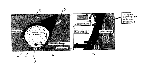
Figure 1A shows a vertical section perpendicular to the horizontal well pair
used in a
recovery process according to the present invention. The outer boundary of the
solvent chamber is denoted by reference numeral 3. Situated below the upper
well 1 is
a production well 5. Hot solvent in vapour form is injected into the upper
injection well
1 as denoted by arrows 7.
During the start-up period and prior to well conversion, the volume I region
between the
injection well 1 and the producing well 5, is pre-heated by circulation of hot
solvent until
sufficient hydraulic communication is established between the upper and lower
wells.
Bitumen/EHO flows (9) into the well.
Injection of hydrocarbon solvents as mentioned above causes a mixture of
bitumen/EHO and solvent to:
- drain downwards by gravity and sideways by pressure gradient to the lower
well
and
- be produced to the surface through the lower well by conventional well
lifting
means including down-hole pumps.
31058858-1-klees
CA 02730680 2011-02-04
MSC PX209522WO
11
At the surface, the solvent can be recovered for recycling.
Figure 1 B shows an expanded detail of the solvent chamber - bitumen/EHO
transition
region. Solubilisation of solvent into the bitumen/EHO occurs by diffusive and
convective mixing in the solvent chamber - bitumen/EHO transition region. The
bitumen/EHO is de-asphalted in the presence of higher solvent concentration.
As a
result of both phenomena stated above, a lower viscosity mixture of
bitumen/EHO and
solvent flows by gravity drainage to the producing well 5.
Figures 2A through 2C show how a non-condensable gas may be used for solvent
recovery and/optimised EHO/bitumen recovery by the provision of alternating
cycles of
solvent and gas injection.
Figure 2A shows the solvent chamber as used in the process described above
with
reference to Figures 1A and 1 B. The reference numerals refer to the same
integers as
in the earlier drawings. The solvent is introduced at a temperature of approx.
250 C
and at an injection mass rate per meter well of about 300 kg/day.
Figure 2B shows the situation after a single injection of non-condensable gas
in the
form of methane and/or nitrogen. In this case, the gas is injected into the
well used for
introduction of solvent, after solvent injection has been stopped. The gas is
also
introduced at a temperature of around 250 C and at a gas injection rate of
approx. 2%
of the solvent injection rate in order to allow for segregation. It can be
seen that a gas
blanket 11 forms at the top of the solvent chamber 3. This exposes new bitumen
wedges for subsequent recovery.
Figure 2C shows the situation after subsequent further cycles of solvent
injection and
gas injection. The gas blanket 11 increases in volume. Recovery is further
enhanced.
Eventually, sufficient gas may be injected to displace most of the solvent for
recovery,
thus improving the overall efficiency of the process. A typical cycle length
for the
solvent injection is approx. 6 months, followed by a 3-month period of gas
injection.
Figure 3 is a sketch of a physical model used to verify the superheated
solvent
recovery process according to an embodiment of the present invention. A
cannister 2
having the dimensions 10cm (a) x 80m (b) x 24cm (c) represents a small scale
(1:100)
model of a 2-dimensional symmetry element of a reservoir perpendicular to a
pair of
31058858-1-klees
CA 02730680 2011-02-04
M&C PX209522W0
12
injection and production wells 1, 5. The cannister was packed with sand and
saturated
with water and bitumen. The process was then carried out with butane being
injected
into the cannister at a injection temperature from 150 C to 300 C with high
grade
bitumen being recovered via the production well.
The results from the experiments carried out demonstrate the suitability of
the process
for the recovery of bitumen and extra heavy oil. The process is capable of
achieving
high ultimate oil (bitumen) recoveries (approx. 80%) and the produced bitumen
generally has an API 2-4 units higher than the original bitumen due to
asphaltene
precipitation in the model. The physical experiments have been simulated with
numerical reservoir simulators and reproduced with reasonable accuracy. The up-
scaled simulation results indicate that a production plant of 40,000 bbl/day
would have
a potential of an economy (NPV) that is better than SAGD and would use approx.
50-
67% of the energy used in SAGD.
In the light of the described embodiments, modifications to these embodiments,
as well
as other embodiments, all within the spirit and scope of the present
invention, for
example as defined by the appended claims, will now become apparent to persons
skilled in the art.
31058858-1-klees