Note: Descriptions are shown in the official language in which they were submitted.
EXTERIOR TRIM FOR MOTOR VEHICLE DOOR FRAME,
AND SEALING MODULE INCORPORATING SAME
FIELD OF THE INVENTION
The present invention relates to an exterior trim for a frame of a glazed side
or rear
door of a motor vehicle and to a sealing module incorporating it. The
invention notably
applies to sealing modules for exterior glass run channel profile strips for
doors with hidden
frames used in motor vehicles.
BACKGROUND
In a known way, exterior trims fitted to sealing profile strips of the run
channel or
window sealing strip type for the mobile glazing of a motor vehicle perform a
function of
decorating or improving the appearance of the sealing profile strips that they
cover and these
trims, like the sealing profile strips that accept them, are generally made of
rigid profile strips
(typically made of metal or, by way of alternative, of a rigid or semi-rigid
thermoplastic
material, the latter then including a reinforcing structure) which are
assembled onto the
corresponding profile strips. These exterior trims can be attached to the
bodyshell of the
vehicle, in which case they are called "gutters" or double lip seal against
bodyshell, or
alternatively to a door of the vehicle, they in this case being exterior door
frame trims,
whether these be vertical or horizontal. Among such glass run channel exterior
trims for
hidden frame doors a distinction is usually made, in the case of the extruded
profile strips,
between: a first family which includes trims which are attached directly to
the rebate of the
door frame and to which the glass run channel and the double lip seal portion
are added, a
second family which includes trims which are attached to the door frame and
which also pass
through the sealing profile strip which acts as a double lip seal and a glass
run channel, and
a third family which includes trims which are attached to the profile strip
that forms the glass
run channel, but without making direct contact with the door frame.
Exterior trims in this first family are usually extruded metal held on the
rebate of the
door frame by added metal clamps, screws or pop rivets. A major disadvantage
with these
trims is that they often require re-machining or rework operations (bending to
shape the
ends, curving to follow the curvature of the frame, molding to sort out the
ends if these ends
are not bendable in the case of steel), the addition of end fittings and
finally machining to
prepare reg ions at which these clips can be fitted.
1
CA 2731148 2017-08-15
Other disadvantages with known trims from this first family lie in the surface
treatment
and/or painting operation (for the "full gloss" black appearance), depending
on the
appearance desired: chrome, full gloss black, matt, gun metal, etc., in their
high cost of
manufacture, in the use of aluminum or stainless steel to avoid corrosion (the
latter material
in fact being very difficult to bend at the ends), in their relatively high
weight, and even in the
need to bond the trim if its shape evolves over its length.
Document EP-B1-1 232 887 discloses an exterior trim for a door with hidden
frame
which is injection molded from a thermoplastic material and has a cross
section substantially
in the shape of a T and is for example force-fitted via a U-shaped clamping
portion that it
includes onto a flat door frame rebate. This rebate may terminate in an
arrowhead-shaped
axially external end.
The trim described in that document has the notable disadvantage of being
difficult to
mold because of the small dimensions and continuity of its U-shaped clamping
portion.
Another disadvantage with this trim is that it is unable by itself to support
the double lip seal
profile strip for sealing against the bodyshell with which strip it is simply
in contact.
SUMMARY OF THE INVENTION
It is an abject of the present invention to propose an exterior trim for a
frame of a
glazed side or rear door of a motor vehicle which is able to overcome these
disadvantages,
the trim being able to be attached directly to a rebate of the frame and being
intended to hold
on this frame at least one sealing profile strip of the glass run channel type
and a double lip
seal for sealing against this bodyshell, this trim comprising a portion for
clamping onto the
rebate which has a substantially U-shaped cross section with two longitudinal
axial legs.
To this end, a trim according to the invention is such that a plurality of
male and/or
female catching means are formed spaced along the length of at least one of
said legs, or
catching leg facing the other leg and are designed to cooperate respectively
with a plurality
of complementary female and/or male catching elements formed spaced along the
length of
said rebate.
It will be noted that a trim according to the invention thus defined may be
fitted in the
overall Y direction (axial direction) of the vehicle that is to accept it via
the upper rebate of its
relevant door frame.
2
CA 2731148 2017-08-15
Advantageously, said catching nneans may comprise parts projecting toward said
other leg and/or recessed or hollowed parts, these catching means being formed
somewhere
short of the axially inner free end of said catching leg.
According to another feature of the invention, said trim comprises an axially
outer
bearing portion comprising the web of said U-shaped clamping portion and
extending it at
least on one of its sides, or glass run channel side, via which the trim is
intended to bear
against said glass run channel profile strip, preferably via at least one
longitudinal bearing lug
extending axially inward and designed to engage in a corresponding axial
recess of this
profile strip.
Advantageously, said bearing portion may further extend said web on an
opposite
side to said glass run channel side, or double lip seal side, via which the
trim is intended to
bear against said double lip seal profile strip, this trim having
substantially the shape of a
lin cross section.
According to another feature of the invention, said bearing portion and at
least said
other leg may be single-shot or multi-shot injection molded from one or more
thermoplastic
materials chosen from the group consisting of filled materials based on
thermoplastic
material polymers, thermoplastic material elastomers (TPEs) and mixtures
thereof, and
preferably based on a polypropylene, optionally filled with talc or with glass
fibers, or
alternatively based on an acrylonitrile-butadiene-styrene (ABS) terpolymer
optionally mixed
with a polypropylene or with a polycarbonate (PC).
Advantageously, said bearing portion may have an axially exterior fair face
consisting
of at least one layer of a film and/or of a metal foil which is added on, for
example by bonding
or clipping, or is alternatively formed as one piece with said bearing portion
by overmolding
or multi-shot injection molding.
As an alternative, the fair face of the bearing portion may be obtained by a
catalytic
chrome plating bath or by painting.
According to a first embodiment of the invention, said trim is molded by
single-shot or
multi-shot injection molding with one or more thermoplastic materials which
forms(form) said
catching leg, said other leg and an axially external bearing portion joining
them together, this
trim being formed as one piece over a given cross section.
According to this first embodiment of the invention, said two legs may be:
both
continuous over the length of the trim, or alternatively both discontinuous
over the length
3
CA 2731148 2017-08-15
thereof, being formed of a plurality of leg sections arranged in a staggered
configuration for
these two legs, the sectors of said catching leg each having one of said
catching means.
Again according to this first embodiment, said catching means may comprise a
plurality of obliquely projecting tabs, for example rectangular tabs, which
are formed spaced
apart over the face of said catching leg facing said other leg and which are
respectively
designed to collaborate by snap-fastening with cavities (blind cavities or
through cavities) of
said rebate forming said catching elements, or alternatively a plurality of
cavities (blind
cavities or through cavities) for example rectangular cavities formed spaced
apart through
said catching leg and which are intended to be filled by snap-fastening by
obliquely
projecting tabs forming said catching elements on the opposing face of said
rebate.
According to a second embodiment of the invention, said trim comprises: an
external
trim body with a cross section substantially in the shape of an asymmetric L
or T, this body
having a bearing portion which forms the base of the L or the top of the T and
which is
intended to hold said glass run channel profile strips and double lip seal
profile strips in place
and a single leg intended to receive this double lip seal profile strip, and a
plurality of plastic
or metal clips which are immobilized in a spaced apart manner against and
inside the trim
body along the length thereof and which have an upper branch and a lower
branch together
defining a clamp clamping onto said rebate, said lower branch defining said
catching leg of
the trim which, in relation with the leg of the trim body forms said clamping
portion of the trim.
According to this second embodiment of the invention, said upper branch of the
clamp formed by each clip defines a holding region holding the latter in
abutment in said trip
body, this holding region being substantially parallel to said leg of this
trim body.
Again according to this second embodiment, said lower branch of each clip has
a
protruding catching part which curves in toward said leg of the trim body and
is intended to
become wedged in a cavity of said rebate, which is preferably a through-
cavity.
With reference to these two embodiments of the invention, it will be noted
that a trim
according to the invention is able to address the aforementioned disadvantages
of the prior
art relating to the weight, the cost of manufacture and the appearance of
existing trims of the
aforementioned first family. This trim may have varying appearances according
to how it is
produced, for example a chrome finish, a full gloss black finish, a matt black
finish, etc.
Because this door trim is advantageously injection molded, it can adopt a
varying
geometry, varying longitudinally or laterally, particularly on its visible
face, and may be
broken down into one or more pieces on the vertical or upper members of the
front or rear
4
CA 2731148 2017-08-15
side door frames, namely on the upright of the opening or "A-pillar" on the
front upper frame
(front or rear "B-pillar'') and on the rear door upper frame or "C-pillar''.
This trim according to the invention may also be able to retain the double lip
seal
profile strip, whether the latter is manufactured by extrusion or injection
molding (single-shot
or multiple shot) by being attached to the trim or alternatively whether it is
incorporated
directly into the trim for example by co-injection molding or multi-shot
injection molding.
ln addition to its appearance function, such a trim according to the invention
may also
serve to hold the run channel profile strip or strips in combination or
otherwise with said door
frame rebate. One or more of these glass run channel profile strips which
provide sealing
between the door frame (via the trim) and the window may be: one or more
extruded profile
strips added between the trim and the door frame, or alternatively at least
one extruded or
injection molded sealing lip which is intended to press against the door
glazing and which is
caught on a protruding lower edge of the trim, for example of bail, bull-nose
or harpoon
shape, via a C-shaped catching region of said at least one lip, or
alternatively at least one
sealing lip which is intended to press against the glazing of said door and
which is connected
as a single piece to a lower edge of the trim, preferably via overmolding or
co-injection
molding with the trim.
A sealing module according to the invention comprises: an exterior trim for
the frame
of a glazed side or rear door of a motor vehicle as defined hereinabove, the
trim being able
to be attached directly to a rebate of the frame and being intended to hold on
this frame at
least one sealing profile strip of the glass run channel type, and the rebate
which comprises
said plurality of female and/or male catching elements formed spaced along the
length and
designed to cooperate with said plurality of complementary male and/or female
catching
means formed along the length of said at least one catching leg.
According to another aspect of the invention, this sealing module is of the
type further
comprising a double lip seal profile strip comprising a rigid base which is
intended to be in
contact with the trim, and a sealing part, for example of the type having
lip(s) and/or of the
tube type which is intended to seal against the fixed frame of the bodyshell.
According to the
invention, this double lip seal profile strip may advantageously be secured to
the trim at at
least one region of mechanical attachment or of adhesion between said rigid
base and the
one of said legs, or proximal leg, which is adjacent to this base.
According to one example of the invention, said mechanical catching region is
formed
at the respective axially internai ends of said rigid base and of said
proximal leg and is
CA 2731148 2017-08-15
formed by the bent-back axially internai end of this base which catches on a
relief, for
example a bead of circular or oblong section or alternatively of harpoon or
arrowhead type.
According to an alternative form of the invention, said double lip seal
profile strip is
secured to the trim at two mechanical catching regions respectively formed by
two axially
internai and external lugs which are continuous or discontinuous, which lugs
extend
substantially at right angles from that face of said proximal leg which faces
toward this profile
strip and are then bent back away from one another so that this leg equipped
with these lugs
substantially forms an inverted Type lquation herr in cross section, these two
lugs being
caught by the axially internai and external ends, which are bent toward one
another, of said
rigid base which is substantially in the shape of a "n" in cross section.
According to another alternative form of the invention, said double lip seal
profile strip
is secured to the trim by an adhesive bond obtained preferably by co-injection
molding of the
materials of which this profile strip is made with that or those of said
proximal leg.
According to another feature of the invention, said rigid base of said double
lip seal
profile strip may rest substantially flat against said proximal leg of the
trim, or alternatively
diverge progressively from this leg starting from its axially internai end as
far as its axially
external end, against which the trim is mounted, said profile strip preferably
being molded as
a multi-shot injection molding of thermoplastic materials.
It will be noted that this mounting of the double lip seal profile strip flat
on the trim
gives the sealing module according to the invention greater compactness and
that on the
other hand, mounting this profile strip with this progressive spacing makes it
possible to fill
the space between the door frame (via the trim) and the fixed frame member
formed by the
side of the bodyshell.
BRIEF DESCRIPTION OF THE DRAWINGS
Other features, advantages and details of the present invention will become
apparent
from reading the following description of a number of embodiments of the
invention, which
are given by way of non limiting illustration, said description being given
with reference to the
accompanying drawings, in which:
FIG. 1 is a schematic front view of an exterior trim according to the
invention for a
glass run channel with hidden frame of a motor vehicle side door frame,
FIGS. 2A and 2B are views in cross section of two sealing modules according to
the
invention, each one comprising a trim according to said first embodiment
mounted on the
6
CA 2731148 2017-08-15
rebate of the door frame in two different examples of how the catching means
and elements
formed on an upper leg of the trim and on this rebate cooperate,
FIGS. 3A and 3B are views in cross section of two other sealing modules
according to
this first embodiment of the invention with two other examples of how catching
means and
elements formed on a lower leg of the trim and on the rebate cooperate,
FIG. 4A is an enlarged view in cross section of the sealing module of FIG. 3B
notably
illustrating one example of mechanical securing of the double lip seal profile
strip to the
upper leg of the trim,
FIG. 4B is a view in cross section of a sealing module according to an
alternative form
of FIG. 4A illustrating another example of mechanical securing of the double
lip seal profile
strip to the upper leg of the trim,
FIG. 40 is a view in cross section of a sealing module according to an
alternative
form of FIG. 4A, which differs therefrom only in that the fair face of the
trim has a different
structure,
FIG. 4D is a partial view both in cross section and in perspective viewed from
beneath, of a trim according to FIG. 4A, on which the double lip seal profile
strip of this FIG.
4A (with the exception of the sealing part of this profile strip) is caught,
this FIG. 4D notably
showing the structure of tabs or "lancings" that protrude from the lower leg
of the trim,
FIG. 4E is a partial view both in cross section and in perspective viewed from
the
side, of a trim according to FIG. 4D formed of several longitudinal sectors
joined together,
FIG. 5 is an enlarged view of just the double lip seal profile strip of FIGS.
4A, 40, 4D
and 4E, notably showing the multi-material structure of its rigid base and of
its flexible sealing
part,
FIG. 6 is a partial view both in cross section and in perspective viewed
slightly from
the side, of a sealing module still according to said first embodiment but
according to an
alternative form of FIG. 3A which differs therefrom notably by the
discontinuous staggered
way in which the upper and lower legs of the trim are formed and by the fact
that the double
lip seal profile strip is mou nted flat on this upper leg,
FIGS. 6A and 6B are views in cross section of two sealing modules according to
this
first embodiment of the invention, of the type of that of FIG. 6, notably
showing this staggered
arrangement of the two trim legs and the catching means and elements according
to FIG. 3A
in the case of FIG. 6A (perforated lower leg), and according to FIG. 2A in the
case of FIG. 6B
(perforated upper leg),
7
CA 2731148 2017-08-15
FIG. 60 is a view in cross section of a sealing module according to this first
embodiment of the invention, essentially differing from that of FIG. 6A in
that the fair face of
the trim is formed of a decorative film or matai foil,
FIG. 6D is a view in cross section of a sealing module according to this first
embodiment of the invention, showing an alternative form of FIG. 6C in which
this film or foil
is bonded or crimped onto this fair face and onto the bent-back ends thereof,
FIG. 7A is a partial perspective view showing one example of a discontinuous
staggered structure of the two legs of the trim according to FIGS. 6 to 60,
with the catching
cavities formed on its lower leg,
FIG. 7B is a partial perspective view showing another example of a trim
according to
FIG. 6D, supplementing the discontinuous structure of the legs according to
FIG. 7A with the
localized crimping at bent-back portions of the foil of this FIG. 6D,
FIG. 8 is a view in cross section of a sealing module according to the second
embodiment of the invention, showing a clip which is immobilized inside a trim
body and the
lower branch of which forms the lower leg of the trim by catching in a cavity
of the rebate, the
fair face of the trim being formed by a film or foil of the type of FIGS. 6A
to 60 and this
module incorporating a double lip seal profile strip mounted flat along the
upper leg of the
trim after the example of FIGS. 6 to 6D,
FIG. 8A is a view in cross section of a sealing module according to the second
embodiment of the invention, according to an alternative form of FIG. 8 in
which the upper
leg of the trim accepts the double lip seal profile strip spaced apart from it
after the example
of FIG. 4B, the lower branch of the clip here being mounted in two positions,
these
respectively being outside of and in this cavity of the rebate,
FIG. 8B is a view in cross section of a sealing module according to the second
embodiment of the invention in accordance with another alternative form of
FIG. 8 in which
the double lip seal profile strip is formed as a single piece with the trim,
for example by co-
injection molding or multi-shot injection molding, a lower branch of the clip
also being shown
in said two positions,
FIG. 8C is a perspective view of a trim of the type of that of FIG. 8, in
which a clip
according to FIGS. 8 to 8B is mounted,
FIG. 8D is a perspective view of this clip according to FIGS. 8 to 80,
FIG. 9 is view in cross section of a sealing module according to the first
embodiment
of the invention in accordance with an alternative form of FIG. 3B, which
shows the catching
8
CA 2731148 2017-08-15
of a sealing lip associated with the glass run channel profile strip on the
trim, and
FIG. 10 is a view in cross section of a sealing module according to the first
embodiment of the invention in accordance with an alternative form of FIG. 9,
which shows
the formation of a sealing lip associated with the glass run channel profile
strip as a single
piece with the trim.
DETAILED DESCRIPTION
In what follows, the qualifiers "axially internai" and "axially external" will
be used in the
usual way to denote the position of an element of the sealing module toward
the inside and
toward the outside, respectively, in the axial direction Y of the width of the
vehicle (this
transverse horizontal direction Y being, by definition, perpendicular to the
plane XZ defined
by the is longitudinal horizontal X and vertical directions).
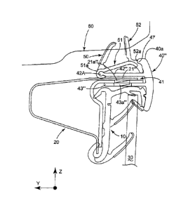
The module 1 visible in the example of FIG. 1 is, for example, mounted on the
rear
side door of the vehicle and further incorporates a double lip seal profile
strip for sealing
against the bodyshell.
As can be seen in FIGS. 2A, 2B, 3A, 3B and 4A, a sealing module 1 according to
the
first embodiment of the invention comprises: at least one sealing profile
strip 10 forming an
exterior run channel of the U-shaped type for a door with a hidden frame 20,
which is
intended to press elastically against the two faces of a glazing 30 of the
door via flexible
sealing lips 11 (preferably made of a single-substance or multi-substance
elastomer
material), an exterior trim 40, 40', 40", 40" of the frame 20, injection
molded in one or more
thermoplastic material(s), which is attached to an upper rebate 21, 21', 21',
21''' of the frame
20 and which holds this glass run channel profile strip 10 on this frame 20,
this trim being
substantially in the shape of a "ir" in cross section and essentially
comprising, on the one
hand, a clamping portion 41, 41', 41", 41" of U-shaped cross section with two
longitudinal
axial legs 42, 42', 42", 42" and 43, 43", 43', for clamping ente the rebate
and, on the other
hand, an axially outer bearing portion 44 comprising the web 45 of the
clamping portion 41 to
41" and extending it on its two sides, and a double lip seal profile strip 50
for sealing against
the fixed frame of the bodyshell 60, which comprises a rigid base 51 intended
to be in
contact with the trim 40 and a sealing part 52 (in this example of the type
having lips 53 and
54) intended to seal against this fixed frame 60, and which is also held on
the door frame 20
by the trim 40.
9
CA 2731148 2017-08-15
More specifically, the bearing portion 44 of the trim 40 to 40" presses
against the
glass run channel profile strip 10 for example via a longitudinal lug 46
extending axially
inward and designed to engage in a corresponding axial recess 12 of this
profile strip 10 and
this bearing portion 44 also presses against the double lip seal profile strip
50.
In the example of FIG. 2A, the upper leg 42 of the trim 40 has, between its
axially
internai and external ends, means of catching on the rebate, these means
consisting of
rectangular cavities 42a which are formed at regular or irregular intervals
along the length of
the trim 40 and into which can be snap-fastened tabs 21a which protrude
obliquely upward
and are formed in the manner of rectangular lancings along the length of the
rebate 21.
In the example of FIG. 2B, the upper leg 42' of the trim 40' has means of
catching on
the rebate 21', these means consisting of oblique rectangular tabs 42a'
protruding obliquely
downward and which are formed at regular or irregular intervals along the
length of the trim
40' between the axially internai and external ends of this leg 42' and which
snap-fastened
into rectangular cavities 21a' formed along the length of the rebate 21'.
ln the example of FIG. 3A, the lower leg 43" of the trim 40" has, between its
axially
internai and external ends, means of catching on the rebate 21', these means
consisting of
rectangular cavities 43a" which are formed at regular or irregular intervals
along the length of
the trim 40" and into which can be snap-fastened rectangular tabs 21a" which
protrude
obliquely downward and are formed along the length of the rebate 21" (it is
possible to elect
to form these rebate tabs 21a or 21a" upward as in FIG. 2A or downward as in
this FIG. 3A
according to the required compactness in the immediate geometric vicinity of
the door frame
20).
In example of FIG. 3B, the lower leg 43" of the trim 40" has means of catching
on the
rebate 21" which consist of rectangular oblique tabs 43a" protruding obliquely
upward and
formed at regular or irregular intervals along the length of the trim 40"
between the axially
internai and external ends of this leg 43" and which snap-fasten into
rectangular cavities 21a"
formed along the length of the rebate 21".
Such tabs 43a" formed in the manner of lancings are illustrated in FIG. 4D
along this
lower leg 43", with reference to FIG. 3B.
FIG. 4A details, likewise for this embodiment of FIG. 3B, one example of
mechanical
catching between the rigid base 51 of the double lip seal profile strip 50 and
the upper leg
42" of the trim 40", via the bulge-like axially internai end 42A of the leg
42" being hooked by
the bent-back axially internai end 51a of the base 51, which extends obliquely
toward the
CA 2731148 2017-08-15
upper edge 40a of the trim 40" which thus presses axially against this double
lip seal profile
strip 50. This double lip seal profile strip 50 is further attached to the
trim 40'" at a second
catching region, directly on the back of the upper edge 40a, by a lug 47
protruding axially
inward from this edge 40a into a housing 52a in the flexible part 52 of the
profile strip 50,
thus locking its position and its sealing contact on the trim 40".
The module according to the alternative form of FIG. 4B differs from that of
FIG. 4A
only in that the double lip seal profile strip 150 is secured to the upper leg
142 of the trim 140
by the double hooking or clipping in the vertical direction Z of two axially
internai and external
lugs 142a and 142b which extend at right angles from the upper face of the leg
and then are
bent back from one another forming substantially the shape of an overturned
"Tr" in cross
section, the hooking being performed by the axially internai and external ends
151a and
151b, which are bent back toward one another, of the base 151 (which is
substantially in the
shape of a "n" or" Q "in cross section).
The double lip seal profile strip 50, 150 of a module according to the
invention can be
manufactured by extrusion (longitudinal cross section constant) or by single-
shot or multiple-
shot injection molding (i.e. notably by co-injection molding), injection
molding allowing this
profile strip 50, 150 to be given a shape that evolves over its length so that
it is better able to
follow the shape of the fixed frame 60 (bodyshell side) and of the trim 40 to
140 along the
entire perimeter concerned. This double lip seal profile strip 50, 150,
depending on its
immediate surroundings, may have a shape as close as possible to the upper leg
42 to 142
of the trim 40 to 140 if there is very little space available (see FIGS. 6 to
60), or on the other
hand may be more distant from this leg 42 to 142 so that it gradually nears
the wall on the
bodyshell 60 side against which it is to seal (see FIGS. 4A and 4C). Its rigid
base 51 to 151
may be based on an EPDM of high Shore D hardness, or on a polypropylene, for
example
containing fillers of talc, glass fiber or hemp, in percentages by mass
ranging from 5% to
60% and preferably of between 20% and 30%. Its flexible part 52 to 152,
whether of tube
type or of the type with lips 53 and 54, may for example be made of a flexible
EPDM of
compact or cellular type, of a flexible TPE of the TPS type (e.g. SEBS) or
flexible TPV (e.g. a
mixture of polypropylene and EPDM) or alternatively a PVC, a styrene elastomer
or a
polyurethane, and this flexible part 52 may continue around the region 42A for
catching on
the trim 40" (see FIG. 4A) in order to ensure a contact with the rebate 21"
which is free of
vibration or parasitic noise. Of course, the materials of which the double lip
seal profile strip
50, 150 is made are chosen with due deference to the mutuel compatibilities of
the materials.
11
CA 2731148 2017-08-15
lt is possible to incorporate a slippery coating, such as an adhesive,
possibly a hot melt
adhesive to which flock has been added, a flocked strip, a co-extruded film of
HDPE (high
density polyethylene) or of high hardness polypropylene, a lacquer, etc. As
already
mentioned, it will be noted that the double lip seal profile strip 50, 150 may
be co-injection
molded directly with the frame trim 40 to 140 in order to ensure that it is
closely bonded
therewith.
In general, with reference to the first embodiment of the invention, the two
legs 42 to
142, 142' and 43 to 143, 143 of this clamping portion 41 to 141 may be
longitudinally
continuous, as may be seen in FIG. 4D, or alternatively, depending on the
environment to
which this portion must conform and for ease of production of the mold and
ease of molding,
they may be discontinuous and arranged in altemation along the length of the
trim 40 to 140
(i.e. in a staggered configuration, see FIGS. 6 to 7B) so that over a given
cross section, just
one leg 42 or 43 to 142 or 143 cooperates by catching with the rebate 21 to
121. FIGS. 6,
6A, 6C and 6D in particular show the snap-fastening of a tab 21a" of the
rebate 21" into a
rectangular through-cavity 43a" of the discontinuous lower leg 143', above
which the upper
leg 142' is locally absent, as visible in FIGS. 7A and 7B which show this
perforated structure
of each portion of lower leg 143' and, by contrast, the solid structure of
each portion of upper
leg 142'.
Still regarding this clamping portion of the trim 40 to 140 it will be noted
that its overall
U shape can be broken down into local tightenings of the U sa that it grips at
isolated points
and that thin longitudinal ribs can also be created inside this U to give the
part stability once it
has been fitted and prevent movements and therefore parasitic noises against
the rebate of
the frame 21 to 121. The entire contact between trim 40 to 140 and rebate 21
to 121 is
mainly governed by the elastic deformation of the U of the clamping portion 41
to 141, which
remains in contact with the sheet metal rebate 21 to 121 thanks to the stress
of deformation.
The clamping portion 41 to 141 of a trim 40 to 140 according to the invention
is made
of a rigid material, possibly filled to give good thermal performance
(resistance to thermal
expansion and contraction observed after the thermal aging cycles contained in
manufacturer specification sheets). This rigid material may, for example, be
based on a
polypropylene reinforced with talc at a mass percentage of 20% or by glass
fiber at a mass
percentage of 30%, or alternatively may be made of ABS (a terpolymer of
acrylonitrile-
butadiene-styrene), possibly mixed with a polycarbonate.
12
CA 2731148 2017-08-15
As for the bearing portion 44 to 144 of the trim 40 to 140, this may be
rounded to
respect the style and lines of the vehicle, visible from the outside and
therefore having to
have a satisfactory fair face 148. The module according to the alternative
form of FIG. 4C
differs from that of FIG. 4A only in terms of its fair face 148, its clamping
portion 41 to 141
being unchanged.
This fair face 148 may be inherent to the material used to injection mold the
trim 40 to
140 for shades such as full gloss black or matt black, in which case the
bearing portion 44 to
144 may have a special material in a fine coat 1/10 mm to 2 mm thick, such as
a decorative
polypropylene or a matt thermoplastic material elastomer (such as a mixture of
polypropylene with EPDM, for example an SEBS).
According to a first alternative form, particularly for so-called "chrome"
finishes, the
chrome plated appearance can be obtained by a catalytic bath, something which
is feasible
only with certain categories of material: ABS, ABS mixed with a polypropylene,
etc. In such
cases the trim 40 to 140 may be fully injection molded in this material.
Accord ing to a second alternative form, in order to obtain the chrome plated
appearance, full gloss black appearance or any other color or pattern, a
bearing portion 144
receives a thin decorative band 148 of chrome or of the desired color or
pattern. This band
may either be a decorative film that already exists on the market (see FIGS.
6A to 6C) or
may be a 5/10 mm stainless steel or aluminum metal foil. According to the
embodiment, this
film or this foil 148 may be: added on to the bearing portion 144 after the
latter has been
injection molded (by fusion, bonding, or even crimping as illustrated in FIGS.
6D and 7B), or
alternatively incorporated into the mold at the time of the injection-molding
of the trim 140,
thus achieving a chemical bond (see FIG. 6C: film with a base compatible with
the injection
molded material, such as a polypropylene, or metal foil with primer) or a
physical bond (see
FIGS. 6D and 7B: the metal foil 248 has upper and lower edges which are bent
back toward
one another and cavities that the injection-molded material will occupy).
Ta do this, and in particular in order to follow the curvature of the trim
140, 240, this
thin decorative band 148, 248 has been either cut to shape to follow this
curvature, or bent
prior to its attachment to the bearing portion 144, 244 or in the mold, or it
naturally has
enough flexibility to conform to this curvature without any previous shaping.
By way of film 148 it is possible, for example, to use a film of a chromium
plated or full
gloss black appearance inside the mold, or a surface treatment (for example
graining).
13
CA 2731148 2017-08-15
When use is being made of a foil 148, 248, it may also be attached using
bonding or
mechanical clamping either continuously or discontinuously (at localized
points). This foil
148, 248 is in the overall shape of a C associated with grooves on its bearing
portion 144,
244 for mounting. The trim 140, 240 may also locally comprise mugs which are
closed over
onto the trim for attachment purposes. It will be noted that this added-on
foil 148, 248 can be
painted or covered with a film to give an appearance other than chrome plated
and that the
decorative foil 148, 248 may also be extruded in the aluminum version, which
allows
solutions for attachment to the trim 140, 240 using shapes other than a C
shape. In general,
it is possible to use a thin foil 148, 248 in aluminum or in stainless steel
(which has been
pressed or extruded) in the mold or even added on by mechanical fastening or
bonding.
It will also be noted that it is possible to incorporate the flocking of the
trim 40 to 240
either: in the mold, via a flocked band positioned in this mold, or
alternatively on leaving the
mold, using a band which is added on or applied using known methods (i.e.
adhesive or
possible hotmelt + flock).
It will also be noted that it is possible to replace the flock with a material
with a low
coefficient of friction, which can either be: incorporated into the mold in
the form of a slippery
film of HDPE type, by injecting or spraying into the mold a fine coat of
slippery material (a
lacquer or slippery polypropylene or alternatively a slippery TPE), or
alternatively added on in
a subsequent operation (spraying or HDPE band, for example).
In the second embodiment of the invention which is illustrated in FIGS. 8 to
8D, the
frame trim 340, which is injection molded in thermoplastic material(s) may be
in the overall
shape of a L in cross section and comprises: comprises: an external trim body
340' having a
bearing portion 344 which forms the base of the L and which is intended to
hold in position
the run channel profile strip 10 and double lip seal profile strip 350, and a
single leg 342
intended to accept this double lip seal profile strip 350, and a plurality of
plastic or metal clips
345 which are mounted in abutment spaced apart inside the trim body 340' along
its length
and which have an upper branch 346 and a lower branch 347 defining a clamp for
clamping
onto the rebate 321 (this clamp is fitted onto this rebate in the axial Y
direction of the
vehicle), the lower branch 347--or catching leg of the trim 340--having a
protruding catching
part 347a which is curved in toward the leg 342 and is intended to become
wedged in a
through-cavity 321 a of the rebate 321.
FIGS. 8, 8C and 8D show that the lower branch 347 of each clip 345 forms, in
relation
with the leg 342 of the trim body 340', the clamping portion 341 of the trim
340 and that the
14
CA 2731148 2017-08-15
upper branch 346 of each clip 345 defines a holding region 346a and 346b
holding the clip in
abutment in the trim body 340, this holding region 346a and 346b being
substantially parallel
to the leg 342.
These figures also show that the trim 340, 340", 340- is provided with a
double lip
seal profile strip 350, 350, 350' which is possibly formed as a single piece
by co-injection
molding (see FIG. 8B) and which allows the run channel profile strip 10 to be
held in
association with the door frame 320.
After the manner of what has been explained hereinabove in respect of the
first
embodiment of the invention, the attachment of this double lip seals profile
strip 350, 350' to
the trim 340, 340", 340" can be achieved via mechanical catching, via: the
hooking of the
bulge-shaped axially internai end 342A of the leg 342 by the bent-back axially
internai end
351a of the base 351 of the profile strip 350 and by the wedging of the upper
edge 340a of
the bearing portion 344 against the axially external end 351b of this profile
strip 350 (see
FIG. 8); or alternatively via the double hooking of two lugs 342a' and 342b'
of the leg 342',
which are analogous to the lugs 142a and 142b of FIG. 4B, by the axially
internat and
external ends 351a and 351b, which are bent back toward one ahother, of the
rigid base 351'
of the double lip seal profile strip 350' (see FIG. 8A).
FIGS. 8C and 8D show an example of a geometry that can be used for these clips
345, with notably the holding portion 346 having two opposing ends 346a and
346b which
become wedged behind an upper rim of the body of the trim 340', and the clamp
the lower
branch 347 of which is bent successively toward this holding portion 346 (in
its catching part
347a) and then away theref rom.
It will be noted that the clips 345 can be bonded to the leg 342 of the trim
340 to
improve their hold, or alternatively may be welded to this leg 342 (in the
case of plastic clips).
As an alternative, these clips 345 may be placed in the mold used for
injection molding the
trim 340 (they then need to have a region that will allow for mechanical
catching of the
injected material).
As illustrated in FIGS. 9 and 10, the trim 440, 540 may be directly provided
with at
least one sealing profile strip or lip 449, 549 to be pressed against the
external face of the
glazing 30, in combination with a run channel profile strip 10' also mounted
on the rebate 21"
(analogous in this example to that of FIG. 4A) pressing against the other side
of the glazing
30.
CA 2731148 2017-08-15
In the example of FIG. 9, the bearing portion 444 of the trim 440 has a
protruding
lower edge 440b on which such an extruded or injection-molded sealing lip 449
is caught via
a C-shaped catching region 449a of the lip cooperating with this protruding
edge 440b which
in this example is of the bail or bulge type.
In the example of FIG. 10, the bearing portion 544 of the trim 540 has a lower
edge
540b to which there is attached, as a single piece, such a sealing lip 549
which is preferably
molded with the trim 540 by overmolding or co-injection molding.
16
CA 2731148 2017-08-15