Note: Descriptions are shown in the official language in which they were submitted.
CA 02731276 2011-02-08
CLEANING PAD AND CLEANING IMPLEMENT
Field of the Invention
The present invention relates to cleaning pads and cleaning implements for
cleaning hard
surfaces, and in particular floors. More particularly, the present invention
relates to the cleaning of
tough stains which tend to be random occurrences but which require aggressive
cleaning to remove
them.
Background of the Invention
Numerous implements are known for cleaning hard surfaces such as tiled floors,
linoleum
floors, hardwood floors, counter tops, and the like. In the context of
cleaning floors, suitable
implements typically comprise a handle and means for applying a liquid
cleaning composition to the
floor. Some implements are reusable, including mops containing cotton strings,
cellulose and/or
synthetic strips, sponges, and the like. While these mops are successful in
removing many soils from
hard surfaces, they typically require the inconvenience of performing one or
more rinsing steps during
use to avoid saturation of the mop with dirt, soil, and other residues. This
requires the use of a
separate container to perform the rinsing step(s), and typically these rinsing
steps fail to sufficiently
remove dirt residues. This can result in redeposition of significant amounts
of soil during subsequent
passes of the mop. Furthermore, as reusable mops are used over time, they
become increasingly soiled
and malodorous. This negatively impacts subsequent cleaning performance.
To alleviate some of the negative attributes associated with reusable cleaning
implements,
mops having disposable cleaning pads have been provided. For example, WO-A-
0027271 describes a
cleaning device comprising a handle and a head portion pivotally attached
thereto, and a removable
cleaning pad for attachment to the head portion, the cleaning pad comprising
at least one absorbent
layer and various other optional features, including a liquid pervious
scrubbing layer to aid in the
removal of tough stains. The scrubbing layer is a monolayer or multilayer
structure, which may
contain openings to facilitate scrubbing of the surface to be cleaned, and
uptake of particulate matter
removed from the surface. The cleaning pad may also comprise an abrasive
scrubbing strip, typically
located in the centre of the lower surface of the cleaning pad, i.e. that
surface which contacts the
surface to be cleaned during normal cleaning operation. A separate scrubbing
strip may be attached to
the leading edge of the head portion of the cleaning implement, which may be
brought into contact
with the surface to be cleaned by tilting the head portion, and turning this
through 900. A key
CA 02731276 2011-02-08
2
challenge in tough stain cleaning is the fact that tough stains are random
occurrences in the home, and
yet require abrasive cleaning to remove them. Examples of common tough stains
include dried
particulate foods, pasta, tomato sautes, and scuff marks. While it is
desirable to have means to
remove tough stains when they occur, it is undesirable to employ those means
across the entirety of
the surface to be cleaned, for fear of damaging that surface. This is
certainly a problem with the
cleaning implement disclosed in WO-A-0027271, where the scrubbing strip is
located on the lower
surface of the cleaning pad, and preferably in the centre of the lower surface
of the cleaning pad.
WO-A-02090483 describes an impregnated wipe, i.e. one that has been pre-
moistened with a
liquid cleaning composition, suitable for cleaning hard surfaces. The wipe
comprises an absorbent
substrate having on one side a textured abrasive surface formed from nodules
and/or striations of
abrasive material having a hardness ranging from 40 to 100 Shore D units. As
the abrasive material
extends over the entirety of the surface of the wipe, use of the wipe may
damage the surface to be
cleaned in areas not suffering from the presence of tough stains.
At present, the only alternative to avoid damage to the surface to be cleaned
is to interrupt the
cleaning process and attempt to remove a tough stain through the use of an
additional cleaning
implement, for instance a brush, cloth or towel. When cleaning a floor, this
requires bending and
hard manual work to remove the tough stain.
Furthermore, a problem associated with the location of a scrubbing strip on
the head portion
of the cleaning implement itself is that particulate material removed as a
result of scrubbing remains
on the cleaning implement. This not only reduces effectiveness of the cleaning
implement over time,
but may also result in redeposition of formerly removed particulate matter,
rendering the whole
cleaning process inefficient.
Summary of the Invention
According to a first aspect of the present invention, a cleaning implement
comprises a handle;
a head portion pivotally attached to the handle comprising an upper surface
and a lower surface
connected to the upper surface by side edges; and a cleaning pad removably
attached to the head
portion, the cleaning pad comprising an absorbent layer which extends over the
lower surface of the
head portion and a scrubbing strip which extends along a side edge of the head
portion.
According to a second aspect of the present invention, a cleaning kit
comprises a cleaning
implement comprising a handle and a head portion pivotally attached thereto;
and a cleaning pad of
the type described above.
According to a third aspect of the present invention, a method of cleaning a
hard surface
comprises providing a cleaning implement comprising a handle and a head
portion pivotally attached
thereto, the head portion having an upper surface and a lower surface
connected to the upper surface
by side edges; attaching to the head portion a cleaning pad of the type
described above, such that the
CA 02731276 2011-02-08
3
absorbent layer extends over the lower surface of the head portion and the
scrubbing strip extends
along a side edge of the head portion; optionally applying a liquid cleaning
composition to the surface
to be cleaned and/or to the head portion of the cleaning implement; wiping the
hard surface with the
cleaning implement; and, optionally, removing the cleaning pad from the head
portion of the cleaning
implement.
According to a fourth embodiment of the claimed invention, a disposable
cleaning pad
comprises a longitudinally-extending central panel comprising an absorbent
layer, and a side panel
abutting at least each longitudinally-extending side of the central panel,
wherein at least one of the
side panels comprises a scrubbing strip, and wherein the central panel is more
highly absorbent than
the side panels. Typically, the central panel comprises at least one third of
the width of the cleaning
Pad.
As is apparent from the above, the cleaning pad for use in the present
invention includes a
scrubbing strip which, when the cleaning pad is attached to a cleaning
implement, does not make
contact with the surface to be cleaned during the normal cleaning operation,
thereby avoiding damage
to the surface to be cleaned. However, when it is desired to remove a tough or
stubborn stain the
cleaning implement may be manipulated, for instance by tilting the head
portion of the implement, in
order to bring the scrubbing strip into contact with the surface to be
cleaned, and a repeated scrubbing
action can be used to remove the tough stain of interest. Once removed from
the surface, the tough
stain material may be disposed of with the cleaning pad, rather than remaining
on the cleaning
implement, thereby avoiding the risk of strain redeposition on further use of
the cleaning implement.
Preferably cleaning pads of this type will be pre-moistened, or impregnated,
with a liquid
cleaning composition.
Definitions
As used herein, the term "x-y dimension" refers to the plane orthogonal to the
thickness of
the cleaning pad, or a component thereof. The x and y dimensions correspond to
the length and width,
respectively, of the cleaning pad or a pad component In this context, the
length of the pad is the
longest dimension of the pad, and the width the shortest. In general, in usc,
a cleaning implement will
be moved in a direction parallel to the y-dimension (or width) of the pad. Of
course, the present
invention is not limited to the use of cleaning pads having four sides. Other
shapes, such as circular,
elliptical, and the like, can also be used. When determining the width of the
pad at any point in the z-
dimension, it is understood that the pad is assessed according to its intended
use.
As used herein, the term "z-dimension" refers to the dimension orthogonal to
the length and
width of the cleaning pad of the present invention, or a component thereof.
The z-dimension therefore
corresponds to the thickness of the cleaning pad or a pad component.
CA 02731276 2011-02-08
As used herein, an "upper" layer of a cleaning pad is a layer that is
relatively further away
from the surface that is to be cleaned (i.e., in the implement context,
relatively closer to the implement
handle during use). The term "lower" layer conversely means a layer of a
cleaning pad that is
relatively closer to the surface that is to be cleaned (i.e., in the implement
context, relatively further
away from the implement handle during use).
As used herein, the "leading" or "front" edge of a cleaning pad is that edge
which on a
forwards wiping motion crosses the surface to be cleaned in advance of the
opposing "trailing" or
"rear" edge of the cleaning pad.
Detailed Description of the Invention
The cleaning pad for use in the present invention comprises an absorbent layer
which serves
to retain any fluid and soil absorbed by the cleaning pad during use. The
absorbent layer may
comprise a single layer or a plurality of layers. Preferably the absorbent
layer comprises a plurality of
layers which are designed to provide the cleaning pad with multiple planar
surfaces and/or density
gradients, as is described in more detail below.
The absorbent layer comprises any material capable or absorbing and retaining
fluid during
use. Typically, the absorbent layer comprises fibrous material, preferably
nonwoven fibrous material.
Fibers useful in the present invention include those that are naturally
occurring (modified or
unmodified), as well as synthetically made fibers. Examples of suitable
unmodified/modified
naturally occurring fibers include cotton, Esparto grass, bagasse, kemp, flax,
silk, wool, wood pulp,
chemically modified wood pulp, jute, ethyl cellulose, and cellulose acetate.
Suitable synthetic fibers
can be made from polyvinyl chloride, polyvinyl fluoride,
polytetrafluoroethylene, polyvinylidene
chloride, polyacrylics such as ORLON , polyvinyl acetate, Rayon ,
polyethylvinyl acetate, non.
soluble or soluble polyvinyl alcohol, polyolefins such as polyethylene (e.g.,
PULPEXCIO) and
polypropylene, polyamides such as nylon, polyesters such as DACRON or KODEL ,
polyurethanes, polystyrenes, and the like. The absorbent layer can comprise
solely naturally occurring
fibers, solely synthetic fibers, or any compatible combination of naturally
occurring and synthetic
fibers.
The fibers useful herein can be hydrophilic, hydrophobic or can be a
combination of both
hydrophilic and hydrophobic fibers. As used herein, the term "hydrophilic" is
used to refer to surfaces
that are wettable by aqueous fluids deposited thereon. Hydrophilicity and
wettability are typically
defined in terms of contact angle and the surface tension of the fluids and
solid surfaces involved.
This is discussed in detail in the American Chemical Society publication
entitled "Contact Angle,
Wettability and Adhesion", edited by Robert F. Gould (Copyright 1964). A
surface is said to be
wetted by a fluid (i.e., hydrophilic) when either the contact angle between
the fluid and the surface is
less than 900, or when the fluid tends to spread spontaneously across the
surface, both conditions
CA 02731276 2011-02-08
normally co-existing. Conversely, a surface is considered to be "hydrophobic"
if the contact angle is
greater than 900 and the fluid does not spread spontaneously across the
surface.
The particular selection of hydrophilic or hydrophobic fibers will depend upon
the other
materials included in the cleaning pad, for instance in different absorbent
layers. That is, the nature of
the fibers will be such that the cleaning pad exhibits the necessary fluid
delay and overall fluid
absorbency. Suitable hydrophilic fibers for use in the present invention
include cellulosic fibers,
modified cellulosic fibers, rayon, polyester fibers such as hydrophilic nylon
(ffYDROFILID). Suitable
hydrophilic fibers can also be obtained by hydrophilizing hydrophobic fibers,
such as surfactant-
treated or silica-treated thermoplastic fibers derived from, for example,
polyolefms such as
polyethylene or polypropylene, polyaerylies, polyamides, polystyrenes,
polyurethanes and the like.
Suitable wood pulp fibers can be obtained from well-known chemical processes
such as the
Kraft and sulfite processes. It is especially preferred to derive these wood
pulp fibers from southern
soft woods due to their premium absorbency characteristics. These wood pulp
fibers can also be
obtained from mechanical processes, such as ground wood, refiner mechanical,
thennomechanical,
chernimechanical, and chemi-therinomechanical pulp processes. Recycled or
secondary wood pulp
fibers, as well as bleached and unbleached wood pulp fibers, can be used.
Another type of hydrophilic fiber for use in the present invention is
chemically stiffened
cellulosic fibers. As used herein, the term "chemically stiffened cellulosic
fibers" means cellulosic
fibers that have been stiffened by chemical means to increase the stiffness of
the fibers under both dry
and aqueous conditions. Such means can include the addition of a chemical
stiffening agent that, for
example, coats and/or impregnates the fibers. Such means can also include the
stiffening of the fibers
by altering the chemical structure, e.g., by crosslinking polymer chains.
Where fibers are used as the absorbent layer (or a constituent component
thereof), the fibers
can optionally be combined with a thermoplastic material. Upon melting, at
least a portion of this
thermoplastic material migrates to the intersections of the fibers, typically
due to interfiber capillary
gradients. These intersections become bond sites for the thermoplastic
material. When cooled, the
thermoplastic materials at these intersections solidify to form the bond sites
that hold the matrix or
web of fibers together in each of the respective layers. This can be
beneficial in providing additional
overall integrity to the cleaning pad.
Amongst its various effects, bonding at the fiber intersections increases the
overall
compressive modulus and strength of the resulting thermally bonded member. In
the case of the
chemically stiffened cellulosic fibers, the melting and migration of the
thermoplastic material also has
the effect of increasing the average pore size of the resultant web, while
maintaining the density and
basis weight of the web as originally formed. This can improve the fluid
acquisition properties of the
thermally bonded web upon initial exposure to fluid, due to improved fluid
permeability, and upon
CA 02731276 2011-02-08
6
subsequent exposure, due to the combined ability of the stiffened fibers to
retain their stiffness upon
wetting and the ability of the thermoplastic material to remain bonded at the
fiber intersections upon
wetting and upon wet compression. In net, thermally bonded webs of stiffened
fibers retain their
original overall volume, but with the volumetric regions previously occupied
by the thermoplastic
material becoming open to thus increase the average inter fiber capillary pore
size.
Thermoplastic materials useful in the present invention can be in any of a
variety of forms
including particulates, fibers, or combinations of particulates and fibers.
Thermoplastic fibers are a
particularly preferred form because of their ability to form numerous
interfiber bond sites. Suitable
thermoplastic materials can be made from any thermoplastic polymer that can be
melted at
temperatures that will not extensively damage the fibers that comprise the
primary web or matrix of
each layer. Preferably, the melting point of this thermoplastic material will
be less than about 90 C,
and preferably between about 75 C and about 175 C. In any evenµ the melting
point of this
thermoplastic material should be no lower than the temperature at which the
thermally bonded
absorbent structures, when used in the cleaning pads, are likely to be stored.
The melting point of the
thermoplastic material is typically no lower than about 50 C.
The thermoplastic materials, and in particular the thermoplastic fibers, can
be made from a
variety of thermoplastic polymers, including polyolefins such as polyethylene
(e.g., PULPEXO) and
polypropylene, polyesters, copolyesters, polyvinyl acetate, polyethylvinyl
acetate, polyvinyl chloride,
polyvinylidene chloride, polyacrylics, polyatnides, copolyamides,
polystyrenes, polyurethanes and ,
copolymers of any of the foregoing such as vinyl chloride/vinyl acetate, and
the like. Depending upon
the desired characteristics, suitable thermoplastic materials include
hydrophobic fibers that have been
made hydrophilic, such as surfactant-treated or silica-treated thermoplastic
films derived from, for
example, polyolefins such as polyethylene or polypropylene, polyacrylics,
polyamides, polystyrenes,
polyurethanes and the like. The surface of the hydrophobic thermoplastic fiber
can be rendered
hydrophilic by treatment with a surfactant, such as a nonionic or anionic
surfactant, e.g., by spraying
the fiber with a surfactant, by dipping the fiber into a surfactant or by
including the surfactant as part
of the polymer melt in producing the thermoplastic fiber. Upon melting and
resolidification, the
surfactant will tend to remain at the surfaces of the thermoplastic fiber.
Suitable surfactants include
nonionic surfactants such as Brij 76 manufactured by ICI Americas, Inc. of
Wilmington, Delaware,
and various surfactants sold under the Pegosperse trademark by Glyco
Chemical, Inc. of
Greenwich, Connecticut. Besides nonionic surfactants, anionic surfactants can
also be used. These
surfactants can be applied to the thermoplastic fibers at levels of, for
example, from about 0.2 to about
I g. per sq. of centimeter of thermoplastic fiber.
Suitable thermoplastic fibers can be made from a single polymer
(tnonocomponent fibers), or
can be made from more than one polymer (e.g., bicomponent fibers). As used
herein, "bicomponent
CA 02731276 2011-02-08
7
fibers" refers to thermoplastic fibers that comprise a core fiber made from
one polymer that is encased
within a therrnoplastic sheath made from a different polymer. The polymer
comprising the sheath
often melts at a different, typically lower, temperature than the polymer
comprising the core. As a
result, these bicomponent fibers provide thermal bonding due to melting of the
sheath polymer, while
retaining the desirable strength characteristics of the core polymer.
Suitable bicomponent fibers for use in the present invention can include
sheath/core fibers
having the following polymer combinations: polyethylene/poly-propylene,
polyethylvinyl
acetate/polypropylene, poly-ethylene/polyester, polypropylene/polyester,
copolyester/ polyester, and
the like. Particularly suitable bicomponent thermoplastic fibers for use
herein are those having a
polypropylene or polyester core, and a lower melting copolyester,
polyethylvinyl acetate or
polyethylene sheath (e.g., those available from Danaklon a/s and Chisso
Corp.). These bicomponent
fibers can be concentric or eccentric. As used herein, the terms "concentric"
and "eccentric" refer to
whether the sheath has a thickness that is even, or uneven, through the cross-
sectional area of the
bicomponent fiber. Eccentric bicomponent fibers can be desirable in providing
more compressive
strength at lower fiber thicknesses. Preferred bicomponent fibers comprise a
copolyolefin
bicomponent fiber comprising less than about 81% polyethylene terephthalate
core and a less than
about 51% copolyolefin sheath. Such a preferred bicomponent fiber is
commercially available from
the Hoechst Celanese Corporation, in New Jersey, under the trade name CELBONDS
T-255. The
amount of bicomponent fibers will preferably vary according to the density of
the material in which it
is used.
Methods for preparing thermally bonded fibrous materials are described in U.S.
Patent No.
5,607,414 (Richards et al), issued March 4, 1997; and U.S. Patent No.
5,549,589 (Homey et al)
issued August 27, 1996 (see especially columns 9 to 10). Such foams and
methods for their
preparation are described in U.S. Patent No. 5,550,167 (DesMarais), issued
August 27, 1996; and
U.S. Patent No. 5,563,179 (Desmarais et al.), issued October 8, 1996.
It may be desirable to include in the absorbent layer a material having a
relatively high
capacity (in terms of grams of fluid per gram of absorbent material). As used
herein, the term
"superabsorbent material" means any absorbent material having a eg capacity
for water of at least
about 15 gig, when measured under a confining pressure of 0.3 psi. Because a
majority of the
cleaning fluids useful with the present invention are aqueous based, it is
preferred that the
superabsorbent materials have a relatively high g/g capacity for water or
water-based fluids.
Superabsorbent gelling polymers useful in the present invention include a
variety of water-
insoluble, but water-swellable (gelling) polymers capable of absorbing large
quantities of fluids.
These materials demonstrate very high absorbent capacities for water Such
polymeric materials are
also commonly referred to as "hydrocolloids", and can include polysaccharides
such as
CA 02731276 2011-02-08
8
carboxymethyl starch, carboxymethyl cellulose, and hydroxypropyl cellulose;
nonionic types such as
polyvinyl alcohol and polyvinyl ethers; cationic types such as polyvinyl
pyridine, polyvinyl
morpholinione, and N,N-dimethylaminoethyi or N,N-diethylaminopropyl acrylates
and
methacrylates, and the respective quaternary salts thereof. Well-known
materials and are described in
greater detail, for example, in U.S. Patent No. 4,076,663 (Masuda et al),
issued February 28, 1978,
and in U.S. Patent No. 4,062,817 (Westerman), issued December 13, 1977.
Preferred superabsorbent gelling polymers contain carboxy groups. These
polymers include
hydrolyzed starch-acrylonitrile graft copolymers, partially neutralized
hydrolyzed starch-acrylonitrile
graft copolymers, starch-acrylic acid graft copolymers, partially neutralized
starch-acrylic acid graft
copolymers, saponified vinyl acetate-acrylic ester copolymers, hydrolyzed
acryloniirile or acrylamide
copolymers, slightly network crosslinked polymers of any of the foregoing
copolymers, partially
neutralized polyacrylic acid, and slightly network crosslinked polymers of
partially neutralized
polyacrylic acid. These polymers can be used either solely or in the form of a
mixture of two or more
different polymers. Examples of these polymer materials are disclosed in U.S.
Patent No. 3661,875,
U.S. Patent No. 4,076,663, U.S. Patent No. 4,093,776, U.S. Patent No.
4,666,983, and U.S. Patent
No. 4,734,478.
Most preferred polymer materials for use in making the superabsorbent gelling
polymers are
slightly network crosslinked polymers of partially neutralized polyacrylic
acids and starch derivatives
thereof. Most preferably, the hydrogel-forming absorbent polymers comprise
from about 50 to about
95%, preferably about 75%, neutralized, slightly network crosslinked,
polyacrylic acid (i.e. poly
(sodium acrylate/acrylic acid)). Network cmsslinking renders the polymer
substantially water-
insoluble and, in part, determines the absorptive capacity and extractable
polymer content
characteristics of the superabsorbent gelling polymers. Processes for network
crosslinlcing these
polymers and typical network crosslinking agents are described in greater
detail in U.S. Patent No.
4,076,663.
Where superabsorbent material is included in the absorbent layer, the
absorbent layer will
preferably comprise at least about 15%, by weight of the absorbent layer, more
preferably at least
about 20%, still more preferably at least about 25%, of the superabsorbent
material.
The scrubbing snip which, in use, is positioned along a side edge of the head
portion of the
cleaning implement, may take a variety of forms. For instance, the scrubbing
strip may be a
continuous or discontinuous strip of material, optionally in the form of a
pattern.
The scrubbing strip necessarily comprises an abrasive material, to remove
tough stains.
Suitable materials include those often used for making scouring pads,
typically polymers or polymer
blends with or without specific abrasives. Examples of suitable polymers
include thermoplastic
CA 02731276 2011-02-08
9
polymers such as polypropylene, high density polyethylene, polyesters (eg.,
polyethylene
terephthalate), nylon, polystyrene, polycarbonate, and blends and copolymers
thereof.
An alternative to using materials found in typical scouring pads is to use
brushes containing
bristles to achieve scrubbing. Such bristles are typically composed of polymer
or polymer blends,
with or without abrasives. In the context of brushes, bristles made of nylon
again are preferred
because of rigidity, stiffness, and/or durability. A preferred nylon bristle
is that commercially
available from 3M Corp. under the trade name Tynex 612 nylon. These bristles
have shown less
water absorption versus commercial Nylon 66. Reducing the ability of the
present adhesive scrubbing
strips to absorb water is important since water absorption decreases bristle
stiffness and recovery
while impacting scrubbing ability.
Another approach is to use netting or scrim materials to form the scrubbing
strip. Again, the
netting or scrim is typically composed of a polymer or polymer blend, either
with or without
abrasives. The netting or scrim is typically wrapped around a secondary
structure to provide some
bulk. The shape of the holes in the netting can include, but is not limited
to, a variety of shapes such
as squares, rectangles, diamonds, hexagons or mixtures thereof. Typically, the
smaller the area
composed by the holes in the netting the greater the scrubbing ability. This
is primarily due to the
fact that there are more points where the scrim material intersects, as it is
these intersection points that
will contact the floor. An alternative to wrapping netting or scrim is to
apply molten extruded
polymers directly onto a secondary structure such as a non-woven. Upon
solidifying the polymer
would create high point stiffer material as compared to the secondary non-
woven, and thereby
provides scrubbing ability.
Yet another alternative is for the scrubbing strip to comprise abrasive or
coarse particulate
material. A suitable particulate material comprises coarse inks available from
Polytex or coarse
polymers from Vinamul, like Acrylic ABX-30.
The scrubbing strip may be a monolayer or multilayer structure. Preferred
scrubbing layers
take the form of film materials, provided that they have the necessary
flexural rigidity to withstand
repeated scrubbing actions. Suitable film materials generally have a thickness
of at least 2 mils and a
flexural rigidity of at least 0.10 g cm2/cm, measured using the Kawabata
Bending Tester Model
KES-FB, from Kato Tech Co., Ltd.
The typical basis weight for flexural stiff materials suitable for use as the
scrubbing strip
range from 20 to 150 gsm, for instance 30 to 125 gsm. However, it is the
combination of modulus and
thickness that determines flexural rigidity. From a theoretical viewpoint for
a rectangular
homogeneous isotropic plate or film, the flexural rigidity is calculated from
the formula:
CA 02731276 2011-02-08
Ebh3
12
where E is modulus, b is plate width, and h is plate thickness. This formula
indicates the
importance of web thickness.
For webs composed of fibers, the relationship is more complex and both the web
stiffness and
fiber stiffness can be important factors. The flexural rigidity for a single
fiber may be calculated from
the formula:
xEd3
32
where d is the fiber diameter.
As indicated in the above formula, the fiber diameter is significant in
selecting webs that can
be used as the scrubbing strip. Generally, fibers with diameters between 20
and 75 microns are useful.
High modulus or tenacity fibers are also an important factor.
Preferred film materials are pervious to liquids, and in particular liquids
containing soils, and
yet are non-absorbent and have a reduced tendency to allow liquids to pass
back through their
structure and rewet the surface being cleaned. Thus, the surface of the film
tends to remain dry
during the cleaning operation, thereby reducing filming and streaking of the
surface being cleaned
and permitting the surface to be wiped substantially dry.
Preferably the film material comprises a plurality of protrusions extending
outwardly from
the film surface and away from the body of the cleaning pad. Alternatively, or
additionally, the film
may comprise a plurality of apertures.
The protrusions and/or apertures formed in the above-described film materials
may be of a
variety of shapes and/or sizes. For instance, the protrusions may take the
form of flaps that extend
outwardly from the plane of the film material at an angle thereto. The
protrusions may also take the
form of teeth that are rectangular, square or triangular in cross-section, or
they may comprise domes
or conical or frustoconical structures. Optionally, the protrusions may also
comprise apertures
themselves. The apertures may, for instance, be square, rectangular,
triangular, circular, oval and/or
hexagonal in shape, or they may take the form of narrow slits. Another option
is for the apertures to
be tapered or funnel-shaped, such that, preferably, the diameter at the end of
the aperture closest the
floor in use is greater than the diameter at the opposite end of the aperture,
such that the aperture
exhibits a suctioning effect as the cleaning pad is moved across the surface
being cleaned. In
CA 02731276 2011-02-08
II
addition, tapered or funnel-shaped apertures prevent liquid passing back from
the scrubbing strip to
the surface being cleaned.
The protrusions and/or apertures may be arranged in a pattern within the
scrubbing strip. If
so, the protrusions and/or apertures are preferably staggered relative to
adjacent protrusions and/or
apertures in order to enhance stain removing ability.
Specific examples of films that may be used as the scrubbing strip now follow:
1) Flexurally rigid film (as defined by the Kawabata Bending Tester
mentioned above)
having out-of-plane protrusions which may take the form of a rectangular or
other shaped tooth
capable of abrading hard surfaces without substantial loss of shape. The teeth
have walls having at
least two opposing faces.
2) Flexurally rigid film (as defined by the Kawabata Bending Tester
mentioned above)
having a slit structure comprising an overlapping set of cut flaps, with at
least one flap that is raised
out of the plane of the film, and that are capable of adbrading a hard surface
without substantial loss
of shape. Both of these types of film are created by passing a thermoplastic
film or nonwoven web
between counter-rotating rollers comprising intermeshing small discontinuous
quasi-rectangular teeth
on one roller and continuous teeth on the other roller. The size of the
resulting protrusions is similar
to the width of the discontinuous teeth. Typically, the protrusions range from
I to 3 mm in the
machine direction and 0.5 to 3 mm in the cross-machine direction. The height
of the protrusions may
be up to 5 mm.
3) A tufted flexurally rigid nonwoven film where sections of fibres are
raised
substantially perpendicular to the plane of the film. Typical basis weights
lie in the range 20 to 100
g/m2, and the fiber diameter is typically greater than 20 um. Preferred fibers
include high tenacity
fibers such as PET, nylon and polypropylene. The tufted fibers may be either
substantially
continuous fibers or substantially broken fibers.
4) A film comprising multi-sided raised structures resembling domes, and
which have
sufficient structural rigidity to withstand the typical forces exerted during
cleaning without permanent
deformation. Typically, the dome dimensions are in the range 2 to 10 mm in the
cross-machine
direction and 2 to 10 mm in the machine direction.
These domes are created by passing a thermoplastic film or nonwoven web
between counter-rotating
rollers comprising intermeshing small discontinuous quasi-rectangular teeth on
one roller and
intermeshing larger and patterned discontinuous quasi-retangular teeth on the
other roller. The
discontinuous teeth on the later roller are made in a pattern such as groups
of diamonds. Reference is
made in this regard to US Patent No. 5,518,801 issued on May 21, 1996 to
Chappell and US
Patent No. 5.968,029 issued on October 19, 1999 to Chappell. Typically, the
protrusions range
from 1 to 10 mm in the machine directions, and I to 10 mm in the cross-machine
direction. The
domes typically are apertured by the penetration of the film. The resulting
structure is
CA 02731276 2011-02-08
12
a dome with apertures on one side and a pocket containing one or more tee-pee
struts on the other
side. This process may be used for both films and nonwovens.
5) Films having apertures which may have a variety of shapes and which may
be
combined with protrusions, for instance, the apertures may take the form of
squares, rectangles, slits,
circles, ovals or any other shape. The size of the apertures may vary widely
but is typically in the
range 0.5 to 10 mm', for instance 0.5 to 5 mm'. The resulting films may have
0.5 to 50% open area,
typically 0.5 to 5% open area when the film has very small apertures, which
may not be visible to the
naked eye, or 5 to 40% open area where the film has larger apertures.
6) Films or webs having corrugations, for instance having I to 6 folds per
10 mm with
fold heights ranging from 0.05 to 3 mm. The corrugations can be prepared by a
ring roll lamination
process. The films or webs may be apertured.
The scrubbing strip may be positioned such that, in use, it lies along one or
both of the
leading and trailing side edges of the head portion (ie. the "long" side
edges), and/or the scrubbing
strip may be positioned along one or both of the side edges of the head
portion connecting the leading
and trailing side edges (ie. the "narrow" side edges).
In one embodiment, the cleaning pad of the present invention may comprise two
or more
scrubbing strips, typically arranged to be on opposing side edges of the head
portion of the cleaning
implement, for instance the leading and trailing edges and in the direction of
wiping, or on one of
these side edges and an adjacent side edge. These scrubbing layers may
comprise the same material,
or different materials. It may, in certain instances, be advantageous for the
two scrubbing layers to
comprise different materials. For instance, one material may be chosen so as
to loosen tough stains,
and the other to pick up large particles loosened from the stain.
The scrubbing strip may also comprise additives to convey desirable
properties, such as
improved abrasion and resistance, increased stiffness, improved particle pick-
up properties, or scent.
Examples of suitable materials for improving abrasion include silicon carbide,
aluminium oxide,
calcium carbonate and talc. Examples of suitable additives for enhancing
particle pick-up include
waxes. Suitable waxes being disclosed in US Publication No. US2004-163674
published August
26, 2004.
The dimensions of the scrubbing strip can have a significant impact of the
ability to remove
tough stains and soils. Preferably the scrubbing strip extends substantially
the entire length of a side
edge of the head portion of the cleaning implement, when attached thereto.
Typically, the scrubbing
strip is rectangular in shape. For instance, the width (or y-dimension) of the
scrubbing strip is
typically in the range from 5 to 100 mm, preferably from 10 to 60 mm, and most
preferably from 15
to 30 mm. The length (or x-dimension) of the scrubbing strip is typically at
least 20 mm, and
preferably at least 50 mm, and more preferably is at least 100 mm, up to, for
instance, 500 mm, and
CA 02731276 2011-02-08
13
typically up to 300 mm. Most preferably the scrubbing strip extends along the
full length of the
cleaning pad.
Also, increasing the z-dimension (thickness) of the scrubbing strip typically
results in better
tough stain removal. The improvement in tough stain removal by varying the
dimensions of the
scrubbing strip generally applies to scrubbing strips comprising a variety of
materials. In addition,
increasing the z-dimension (thickness) of the scrubbing strip, allows one to
utilize softer materials,
such as polypropylene without abrasive material, in the scrubbing strip while
achieving a similar level
of tough stain removal as compared to scrubbing strips comprising harder
materials, such as nylon.
Also, tough stain removal can be enhanced by incorporating a mixture of
materials in the scrubbing
strip, such as nylon and abrasive materials, such as silicon carbide, aluminum
oxide, calcium
carbonate, and the like, or a combination of a polyester wadding wrapped in a
nylon netting.
The scrubbing strip may be of contrasting colour to the remainder of the
cleaning pad, in
order to facilitate its use, or to include branding information. Where a
number of scrubbing strips are
included on the cleaning pad it may be desirable that these are different
colours, particularly where
the scrubbing strips comprise different materials and serve different
purposes, as described above.
The cleaning pad may comprise at least two distinct panels or sections having
different
degrees of absorbency. For instance, a preferred cleaning pad comprises a
longitudinally-extending
central panel (ie. extending in the x-dimension of the pad) comprising an
absorbent layer, and a side
panel abutting each longitudinally-extending side of the central panel,
wherein at least one of the side
panels comprises a scrubbing strip. On attachment to the head portion a
cleaning implement, the
central panel extends over the lower surface of the head portion and thus
forms the major cleaning
surface. The side panels extend along the side edges of the head portion of
the cleaning implement.
The side panels may also comprise absorbent material, optionally the same
absorbent material as the
central panel, but typically the side panels will be less absorbent to liquid
than the central panel. The
width of the central panel (le. in the y-dimension) will depend upon the width
of the head portion of
the cleaning implement. However, typically, the central panel extends across
at least one third of the
width of the cleaning pad.
It is envisaged that a cleaning pad of this type, and indeed that the cleaning
pads of the
invention in general, may comprise a monolayer or multilayer structure,
excluding from consideration
the scrubbing strip. For instance, in a monolayer structure, panels of
different absorbency may be
provided by using different absorbent materials.
For clarity, in the context of the present invention, when reference is made
to a portion of the
cleaning pad extending over the lower surface of the head portion of a
cleaning implement, this
includes an embodiment in which the portion of the cleaning pad extends only
partially over the
lower surface of the head portion, and an embodiment in which the portion of
the cleaning pad
CA 02731276 2011-02-08
14
extends over substantially the entirety of the respective portion of the head
portion, in either or both
of the length and width dimensions. Typically, the central panel extends along
the entire length of
the cleaning pad but only over a portion of its width.
The cleaning pad may also comprise a scrubbing layer which, when attached to
the cleaning
implement, extends over the lower surface of the head portion of that cleaning
implement. Typically,
the scrubbing layer is outermost on the cleaning pad, and thus contacts the
surface to be cleaned
during the normal course of the cleaning operation. In this case, the
scrubbing layer must necessarily
be of lower abrasiveness than the scrubbing strip, in order not to damage the
surface being cleaned.
The scrubbing layer may be a mono-layer or a multilayer structure. A wide
range of materials
are suitable for use in the scrubbing layer, for instance as disclosed in WO-A-
0027271. In particular,
the scrubbing layer may comprise woven and nonwoven materials; polymeric
materials such as
apertured formed thermoplastic films, apertured plastic films, and hydrofonned
thermoplastic films;
porous foams; reticulated foams; reticulated thermoplastic films; and
thermoplastic scrims. Suitable
woven and nonwoven materials can comprise natural fibers (e.g., wood or cotton
fibers), synthetic
fibers such as polyolefins (e.g., polyethylene, particularly high density
polyethylene, and
polypropylene), polyesters (e.g., polyethylene terephthalate), polyirnides
(e.g., nylon) and synthetic
cellulosics (e.g., RAYON ), polystyrene, and blends and copolymers thereof,
and combinations of
natural and synthetic fibers. Such synthetic fibers can be manufacture known
processes such as
carded, spunbond, meltblown, airlaid, needle punched and the like.
The cleaning pad also typically comprises attachment means for attaching the
pad to a
cleaning implement. Alternatively, the cleaning implement itself may include
suitable attachment
means. For instance, the cleaning pad may have an attachment layer that allows
the pad to be
connected to the implement's handle or head portion. The attachment layer can
be necessary in those
embodiments where the absorbent layer is not suitable for attaching the pad to
the cleaning
implement. The attachment layer can also function as a means to prevent fluid
flow through the top
surface (i.e., the handle-contacting surface) of the cleaning pad, and can
further provide enhanced
integrity of the pad. As with the scrubbing and absorbent layers, the
attachment layer can consist of a
mono-layer or a multi-layer structure, so long as it meets the above
requirements.
In a preferred embodiment of the present invention, the attachment layer will
comprise a
surface which is capable ofbeing mechanically attached to the head portion of
a cleaning implement
by use of known hook and loop technology. In such an embodiment, the
attachment layer will
comprise at least one surface which is mechanically attachable to hooks that
are permanently affixed
to the bottom surface of the head portion.
CA 02731276 2011-02-08
In an alternative embodiment, the attachment layer can have a y-dirnension
(width) that is
greater than the y-dimension of the other cleaning pad elements such that the
attachment layer can
then engage attachment structures located on a head portion of a handle of a
cleaning implement.
The cleaning pad may be designed to have multiple cleaning surfaces or edges,
each of which
contact the soiled surface during the cleaning operation. In the context of a
cleaning implement such
as a mop, these surfaces or edges are provided such that during the typical
cleaning operation (i.e.,
where the implement is moved back and forth in a direction substantially
parallel to the pad's y-
dimension or width), each of the surfaces or edges contact the surface being
cleaned as a result of
"rocking" of the cleaning pad. The effect of multiple edges is achieved by
constructing the pad such
that it has multiple widths through its dimension. That is, these multiple
widths form a plurality of.
surfaces or edges along the front and rear of the pad. This aspect is
discussed in more detail in WO-
A-0027271.
The cleaning pad may also include one or more "free-floating" functional
cuffs. Such cuffs
improve the cleaning performance of the cleaning pad, by improving particulate
pick-up. As a
cleaning pad comprising functional cuff(s) is wiped back and forth across a
hard surface, the
functional cuff(s) "flip" from side to side, thus picking-up and trapping
particulate matter. Cleaning
pads having functional cuff(s) exhibit improved pick-up and entrapment of
particulate matter, which
are typically found on hard surfaces, and have a reduced tendency to redeposit
such particulate matter
on the surface being cleaned. Functional cuffs can comprise a variety of
materials, including, but not
limited to, carded polypropylene, rayon or polyester, hydroentangled
polyester, spun-bonded
polypropylene, polyester, polyethylene, cotton, polypropylene, or blends
thereof. Functional cuffs can
be formed as an integral part of the cleaning pad, or can be separately
adhered to the cleaning pad. If
the functional cuffs are an integral part of the cleaning pad, the functional
cuffs are preferably a
looped functional cuff formed by crimping a lower portion of the cleaning pad,
for example, in a Z-
fold and/or C-fold. Alternatively, the functional cuffs can be separately
adhered to the cleaning pad
via a variety of methods known in the art including, but not limited to,
double-sided adhesive tape,
heat bonding, gluing, ultrasonic welding, stitching, high-pressure mechanical
welding and the like.
Preferably, the cleaning pad comprises two functional cuffs situated at or
near opposite edges
(e.g., the leading and trailing edges of the pad, in terms of the y-dimension)
of the cleaning pad.
Preferably, the functional cuff(s) are placed in a location such that their
length is perpendicular to the
back and forth mopping or wiping direction used by the consumer.
The size of the cleaning pad is determined by the cleaning implement to which
it is to be
attached. Typically, however, the cleaning pad will have dimensions in the
range 100 to 300 mm x
100 to 300 mm (expressed as (x-dimension) x (y-dimension)). Furthermore, the
thickness of the
cleaning pad (expressed as z-dimension) is typically in the range 1 mm to 20
mm, more preferably in
CA 02731276 2013-05-27
16
the range 2 mm to 10 mm, although again this will depend upon the application
to which the
cleaning pad is to be put.
The various layers and/or elements of the present cleaning pad are preferably
bonded
together to form a unitary structure. The various layers and/or elements can
be bonded in a variety
of ways including, but not limited to, adhesive bonding, thermal and or
pressure bonding, ultra-
sonic bonding, and the like. The various layers and/or elements can be
assembled to form a
cleaning pad either by hand or by a conventional line converting process known
in the art.
When the layers and/or elements are adhesively bonded together, the adhesive
is typically
selected so that the bond formed by the adhesive is able to maintain its
strength in wet
environments, especially when the cleaning pad is saturated with fluid and/or
soil. The selection
of the adhesive is particularly important when bonding two absorbent layers
together, bonding an
absorbent layer and an attachment layer together, or bonding an absorbent
layer and a liquid
pervious scrubbing layer together. In this context, the adhesive is typically
selected such that the
adhesive provides a bond with high water resistence, e.g. with a bond
retention of at least about
30%, preferably at least about 50%, and more preferably at least about 70% of
the dry bond
strength value. Bond strength values can be measured according to a partially
modified ASTM D
1876-95 ( 1995) (1-Peel Test) standard method, which is described in detail in
U.S. Patent No.
5,969,025 issued October 19, 1999 to Corzani.
Adhesives that can be used in the present invention include vinylic emulsions,
including
those based on vinyl acetate or other vinyl esters and ranging from
homopolymers to copolymers
with ethylene and/or acrylic monomers (vinyl acrylics); acrylic emulsions
which can be either
homopolymers or copolymers; a cross-linked adhesive including those created by
including a
reactive co-monomer (e.g., a monomer containing carboxyl, hydroxyl, epoxy,
amide, isocyanate,
or the like, functionality) which are capable of cross-linking the polymer
themselves (e.g.
carboxyl groups reacting with hydroxyl, epoxy or isocyanate groups) or by
reaction with an
external cross-linker (e.g. urea-formaldehyde resin, isocyanates, polyols,
epoxides, amines and
metal salts, especially zinc). The adhesives can also include limited
quantities of tackifying resins
to improve adhesion, such as the addition of hydrogenated rosin ester
tackifier to a vinyl
acetate/ethylene copolymer latex. Other suitable water-based adhesive
compositions include those
disclosed in U.S. Patent No. 5,969,025 issued October 19, 1999 to Corzani.
However, it may be difficult to bond some materials using adhesives,
particularly where
their structural integrity is not as strong as the adhesive bond ultimately
formed. In this case, only
those portions of the materials that are in direct contact with the adhesive
will remain bonded to
other materials, and the remainder of the material will readily separate from
the material to which
it was intended to be bonded. Materials of this type may be bonded using the
method described in
U.S. Patent No. 7,056,404, issued June 6, 2006. The bonding technique
CA 02731276 2011-02-08
17
described in this document allows bonding throughout the pad structure without
the need for
thermoplastic materials or adhesives.
Preferably, the pad is bonded or compressed, preferably throughout its
thickness, at selected
locations to form a plurality of discrete reservoirs or pockets within the pad
structure, which are
preferably in fluid communication with one another. This is particularly
preferred in the context of
pre-moistened cleaning pads. The reservoirs serve to reduce drippage when the
cleaning pad is loaded
with, for instance, a liquid cleaning composition.
Bonding may be achieved, for instance, by the application of heat and/or
pressure, or
ultrasonically. In one embodiment, the cleaning pad will comprise an absorbent
core enclosed within
an upper sheet and a lower sheet, and each fluid reservoir will contain a
portion of the absorbent core.
Bonds may take the form of line bonds extending substantially from one edge of
the pad to another
edge of the pad, and intersecting with other line bonds in order to create a
plurality of adjacent
reservoirs. Alternatively, a bonding pattern may be selected so as to create a
plurality of reservoirs
that are separated from one another rather than bordering one another. The
reservoirs may be a
variety of shapes, for instance selected from circles, ovals, diamonds,
squares, rectangles, triangles,
and hexagons, and combinations thereof.
The cleaning pad may be attached to a cleaning implement in dry form or it may
have been
pre-moistened (or impregnated) with a liquid cleaning composition. The
cleaning composition is
selected according to the surface to be cleaned.
The cleaning pad may be used with a variety of cleaning implements. One
example of a
suitable cleaning implement is in the form of a mop comprising a handle and a
head portion (mop
head) pivotally attached to the handle, for instance through a universal
joint. The cleaning implement
may also comprise a liquid delivery system, which may deliver liquid to the
head portion or to the
surface to be cleaned. For instance, the liquid delivery system may take the
form of a spray
mechanism that, in use, sprays a cleaning composition on to the surfs= to be
cleaned in front of the
head portion. The spray mechanism may be operated manually or may be operated
by battery, motor
or by other non-manual means.
The cleaning implement of the present invention may be used to clean a variety
of hard
surfaces. Preferably, however, they are used for cleaning floors. These floors
mainly consist of
ceramics, porcelain, marble, Formica , no-wax vinyl, linoleum, wood, quarry
tile, brick or cement,
and the like.
After attachment of a cleaning pad to the cleaning implement, if the cleaning
pad is of the
dry-type (ie. not pre-moistened) it is necessary to apply a liquid cleaning
composition to the head
portion of the cleaning implement (and thereby the cleaning pad) and/or
directly to the surface to be
cleaned. The liquid cleaning composition may be applied to the cleaning pad
simply by immersing
CA 02731276 2011-02-08
18
the head portion of the cleaning implement into a bucket containing the liquid
cleaning composition,
which may have been diluted depending upon its constituents. In this case, the
cleaning pad should
preferably be wrung out prior to use, so that it is not dripping wet.
Alternatively, the liquid cleaning composition may be delivered directly to
the head portion,
for instance by means included on the cleaning implement, or directly by the
consumer.
Another option is to apply the liquid cleaning composition directly to the
surface to be
cleaned, either in the form of a liquid or spray. This can be achieved via a
separate squirt bottle or
spray trigger system, or can be achieved by means directly attached or built-
in to the cleaning
implement, as described above.
If, however, a pre-moistened cleaning pad is to be used, there will typically
be no need to
apply additional liquid cleaning composition either to the cleaning pad or to
the surface to be cleaned.
Cleaning is effected by wiping the head portion of the cleaning implement
across the surface
to be cleaned. A preferred wiping pattern consists of an up-and-down
overlapping motion starting in
the bottom left hand (or right hand) side of the section to be cleaned, and
progressing the wiping
pattern across the floor continuing to use up-and-down wiping motions. Wiping
is then continued
beginning at the top right (or left) side of the section to be cleaned and
reversing the direction of the
wipe pattern using a side-to-side motion. Another preferred wipe pattern
consists of an up-and-down
wiping motion, followed by an up-and-down wiping motion in the reverse
direction. These thorough
preferred wiping patterns allow the pad to loosen and absorb more solution,
dirt and germs, and
provide a better end result in doing so by minimizing residue left behind.
Another benefit of the
above wiping patterns is minimization of streaks as a result of improved
spreading of solution and the
elimination of streak lines from the edges of the pad.
When it is desired to remove a tough soil or stain from the surface, the head
portion of the
cleaning implement is tilted in order to bring the scrubbing strip on its side
edge into contact with the
tough soil. The tough soil is then removed by repeated, short, back and forth
movements of the
scrubbing strip across the soil.
Typically, after cleaning, the cleaning pad is removed and disposed of, and
with it the germs
and dirt removed from the surface, thereby promoting better hygiene and
malodour control.
However, the cleaning pad may be used for multiple cleaning, depending upon
whether the pad is
saturated with liquid and/or dirt. This can be readily ascertained by the
consumer.
It may be desirable to rinse the surface after cleaning, and it may be
desirable to use a fresh
cleaning pad for this purpose, depending on the level of soiling of the
original pad, or another
product.
Typically, a plurality of cleaning pads are provided in a container or film
wrapping for supply
to the consumer, typically with instructions for attachment to a cleaning
implement. Kits comprising
CA 02731276 2013-05-27
19
a cleaning implement and cleaning pad are also provided, again typically with
suitable operating
instructions.
The present invention is now further described with reference to the
accompanying
drawings.
Figure 1 is a plan view of the lower surface of a cleaning pad for use in the
present invention.
Figure 2 is a perspective view of a cleaning implement according to the
present invention.
Figure 3 is a side view of a cleaning implement according to the present
invention.
Figure 4 is a cross-sectional view of a thermoplastic film according to the
present invention.
With reference to Figure 1, a cleaning pad 1 comprises a longitudinally-
extending central
panel 2 comprising multiple absorbent layers. Longitudinally-extending side
panels 3 abut the
central panel, and in this embodiment comprise absorbent material of lower
absorbency than the
central panel. A scrubbing strip 4 is located on one of the side panels and
extends substantially the
entire length of the side panel.
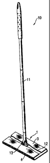
With reference to Figures 2 and 3, a cleaning implement 10 made in accordance
with one
aspect of the present invention is illustrated, cleaning implement 10
comprises a handle 11, a head
portion 12 attached to the handle by a universal joint 13. The cleaning
implement 10 uses a
removably attached cleaning pad substrate 1 for absorbing the cleaning liquid
and particulates
from the surface to be cleaned. The cleaning substrate 1 can be provided in
one or more forms,
such as a liquid absorbent pad or a liquid premoistened pad.
By virtue of its location on the cleaning pad, a scrubbing strip 4 extends
along the leading
edge of the mop. When scrubbing is required, a user of the mop simply turns
the mop around 900,
and places the head portion 12 in an upright position so that the scrubbing
strip contacts the floor.
In one embodiment, the scrubbing strip 4 comprises a thermoplastic film. As
shown in Figure 4, a
plurality of protrusions 17 is formed integrally with and extending outwardly
from the film 15.
The film 15 can also be provided with a plurality of apertures 19.