Note: Descriptions are shown in the official language in which they were submitted.
CA 02731559 2011-01-20
WO 2010/023659 PCT/IL2009/000814
CUTTING TOOL AND ROUND DOUBLE SIDED CUTTING INSERT
THEREFOR
FIELD OF THE INVENTION
The present invention relates to a milling cutting insert having rounded
cutting edges and particularly to a double-sided cutting insert of such a
kind.
BACKGROUND OF THE INVENTION
When producing turbine blades, the fmal machining stage of the internal
surface of the turbine blade is typically done by means of milling cutting
inserts
having round cutting edges. In such a case, the total usable sector used to
cut by
such a cutting insert is usually greater than 120 , therefore, the cutting
insert may
be indexed only two times since a third indexing would not be able to utilize
a full
range sector, i.e., a cutting edge spanning to more than 120 .
Known round cutting inserts or cutting inserts having round cutting edges are
often single sided, and, as mentioned, may fully utilize only two cutting
edges. For
example, US. Pat. No. 4,175,896 discloses a single sided cutting insert having
two
arcuate cutting edges which are eccentric to each other and separated from
each
other by diametrically symmetric flat faces.
Round double sided cutting inserts are typically ceramic inserts and are
devoid a central through bore for the passage of a clamping screw. The lack of
a
through bore is a disadvantage since it requires utilizing a more complex and
CA 02731559 2011-01-20
WO 2010/023659 PCT/IL2009/000814
-2-
expensive retaining system.
It is the object of the present invention to provide a double-sided indexable
cutting insert having four or more round cutting edges.
It is a further object of the present invention to provide a double-sided
indexable cutting insert having four round cutting edges wherein each of the
cutting
edges extends more than 120 .
It is still a further object of the present invention to provide a tool holder
for a
double sided cutting insert having four rounded cutting edges and a through
bore,
the cutting insert being retained within the tool holder be means of a
clamping
screw that passes through the through bore.
SUMMARY OF THE INVENTION
In accordance with the present invention there is provided a cutting
insert for retention in a rotating cutting tool having an axis of rotation,
the cutting
insert comprising:
two opposing end surfaces and a peripheral side surface extending
therebetween, each end surface having a mutual first axis of symmetry passing
through the end surfaces about which each end surface has N-fold rotational
symmetry for some value of N where N is chosen from the group of 2, 3 and 4;
a peripheral cutting edge formed at the junction between each end surface and
the peripheral side surface, the peripheral edge comprising N curved cutting
edges
merging with N straight cutting edges which extend between the curved cutting
edges at extremities thereof; wherein:
the curved cutting edges of the two end surfaces do not overlap in an end
view of the cutting insert along the first axis of symmetry.
Typically, N cutting edge axes, located in a mid portion of each of the
N curved cutting edges, extend parallel to the first axis of symmetry, and
each of the N curved cutting edges of one of the end surfaces is rotated about
its associated cutting edge axis relative to an opposite curved cutting edge
of the
other end surface, as seen in an end view of the cutting insert along the
first axis of
CA 02731559 2011-01-20
WO 2010/023659 PCT/IL2009/000814
-3-
symmetry.
Advantageously, each of the N curved cutting edges lies on a torus.
Further advantageously, each operative curved cutting edge sweeps out
a portion of a torus when the cutting insert is retained in the rotating
cutting tool
and the rotating cutting tool is rotated about its axis of rotation by 360 .
In one embodiment, one extremity of any given curved cutting edge is
located further from a median plane of the cutting insert than the other
extremity of
the given curved cutting edge, the median plane being located midway between
the
end surfaces.
In one embodiment, the curved cutting edges associated with one of the
end surfaces are located in a first reference plane and the curved cutting
edges
associated with the other end surface are located in a second reference plane,
the first and second reference planes being parallel to each other and located
equidistant from and on either side of a median plane of the cutting insert,
the
median plane being located midway between the end surfaces.
Typically, the cutting insert comprises a through bore, having a through
bore axis constituting the first axis of symmetry, that extends between the
two end
surfaces; and
the peripheral surface comprises a first, second, third and fourth pairs of
side
abutment surfaces, each pair of side abutment surfaces has 180 rotational
symmetry around the through bore axis.
In one embodiment, the two end surfaces are identical.
If desired, a major portion of each of the curved cutting edges extends
along an angle equal to or larger than 120 as seen along the first axis of
symmetry.
In one embodiment, a first end surface of the two opposing end surfaces
constituting an upper surface defining a first reference plane, a second end
surface
of the two opposing end surfaces constituting a lower surface defining a
second
reference plane parallel to the first reference plane;
the curved cutting edges comprise a first main cutting edge and a second main
cutting edge;
CA 02731559 2011-01-20
WO 2010/023659 PCT/IL2009/000814
-4-
in an end view of the cutting insert the first main cutting edge has a first
radius of curvature with respect to a first cutting edge axis and the second
main
cutting edge has a second radius of curvature with respect to a second cutting
edge
axis,
the first cutting edge axis and the second cutting edge axis are parallel to
the
through bore axis and located at opposite sides thereof;
the first cutting edge axis is located a first distance from the second main
cutting edge, the through bore axis is located a second distance from the
second
main cutting edge, and the first distance is smaller than the second distance.
Typically, the cutting insert has 180 rotational symmetry around a
second symmetry axis, the second symmetry axis lies on a median plane between
the first and the second reference planes, and intersects the peripheral
surface at
two insert symmetry points;
each of the insert symmetry points is formed at the intersection of a first
reference line with a second reference line, as seen in a first side view of
the cutting
insert that is perpendicular to a given secondary cutting edge;
the first reference line connects the leading end of a first main cutting edge
of
a given end surface with the leading end of a first main cutting edge of an
opposite
end surface; and
the second reference line connects the trailing end of a second main cutting
edge of a given end surface with the trailing end of a second main cutting
edge of
an opposite end surface.
In one embodiment, the first cutting edge axis and the second cutting
edge axis are located at opposite sides of an imaginary plane that is
perpendicular
to a symmetry plane that contains the first axis of symmetry and the second
symmetry axis.
Further in accordance with the present invention there is provided a
cutting insert for retention in a rotating cutting tool having an axis of
rotation, the
cutting insert comprising:
two opposing end surfaces and a peripheral side surface extending
CA 02731559 2011-01-20
WO 2010/023659 PCT/IL2009/000814
-5-
therebetween, each end surface having a mutual first axis of symmetry passing
through the end surfaces about which each end surface has 180 rotational
symmetry;
a peripheral cutting edge formed at the junction between a first end surface,
constituting an upper surface, and the peripheral side surface, the peripheral
edge
comprising two curved cutting edges merging with two straight cutting edges
which extend between the curved cutting edges at extremities thereof;
a continuously extending rake surface extends inwardly from the peripheral
cutting edge, the rake surface is slanted at a rake slant angle with respect
to a
second end surface, constituting a lower surface;
the upper surface comprises a rake inner extremity at the innermost extremity
of the rake surface and a bore upper end at the upperinost end of a through
bore
that extends between the end surfaces, a length between a given point on the
peripheral cutting edge and the rake inner extremity comprises a first rake
length
and a length between the given point and the bore upper end comprises a second
rake length, the first rake length and the second rake length taken in a plane
parallel
to the lower surface; wherein:
the rake slant angle is equal to or greater than 25 ;
a rake extension ratio, defined as a ratio between the first rake length and
the
second rake length, is smaller than 1 and equal to or greater than 0.8; and
a major portion of each of the curved cutting edges lies on a torus and
extends
along an angle equal to or larger than 120 as seen along the first axis of
symmetry.
Typically, the peripheral surface comprises a first pair of side abutment
surfaces that converge towards each other in a direction toward the upper
surface,
and, a third pair of side abutment surfaces that converge towards each other
in a
direction toward the upper surface.
Still further in accordance with the present invention there is provided a
cutting tool having a longitudinal axis of rotation and comprising:
a tool body having at least one insert pocket formed in a front end of the
tool
body and a cutting insert according to claim 1 retained in the at least one
insert
CA 02731559 2011-01-20
WO 2010/023659 PCT/IL2009/000814
-6-
pocket, the at least one insert pocket comprising:
a pocket tangential abutment surface;
a threaded bore extending tangentially rearwardly from the pocket tangential
abutment surface;
pocket side walls extending upwardly from the pocket tangential abutment
surface, two spaced apart of the pocket side walls are a first pocket abutment
surface, forming an acute first pocket internal angle with the pocket
tangential
abutment surface, and a second pocket abutment surface, forming an acute
second
pocket internal angle with the pocket tangential abutment surface;
the cutting insert comprises:
a first, second, third and fourth pairs of side abutment surfaces, each pair
of
the side abutment surfaces has 180 rotational symmetry around the through
bore
axis,
the first pair of side abutment surfaces converge towards each other in a
direction toward the upper surface,
the second pair of side abutment surfaces converge towards each other in a
direction toward the lower surface,
the third pair of side abutment surfaces converge towards each other in a
direction toward the upper surface,
the fourth pair of side abutment surfaces converge towards each other in a
direction toward the lower surface,
the third pair has 180 rotational symmetry with the fourth pair around a
second symmetry axis that passes between the third pair and the fourth pair,
the upper surface defines a first reference plane and the lower surface
defines
a second reference plane, the first and second reference planes are parallel
to a
median plane that is located midway between the upper surface and the lower
surface,
the peripheral surface forms with the first reference plane and with the
second
reference plane an obtuse first internal included angle, as seen in a first
side view of
the cutting insert that is perpendicular to a given secondary cutting edge,
CA 02731559 2011-01-20
WO 2010/023659 PCT/IL2009/000814
-7-
the peripheral surface forms with the first reference plane and with the
second
reference plane an acute second internal included angle, as seen in a second
side
view of the cutting insert that is perpendicular to the first side view,
the upper surface is provided with a planar upper central abutment surface,
constituting an insert upper tangential abutment surface, that extends
inwardly from
an associated rake surface toward the through bore;
the lower surface is provided with a planar lower central abutment surface,
constituting an insert lower tangential abutment surface, that extends
inwardly from
the associated rake surface toward the through bore; wherein:
in a retained position of the cutting insert, the insert lower tangential
abutment surface abuts the pocket tangential abutment surface, one abutment
surface of the insert first pair of side abutment surfaces abuts the first
pocket
abutment surface, one abutment surface of the insert third pair of side
abutment
surfaces abuts the second pocket abutment surface, and, a clamping screw
passes
through the through bore of the cutting insert and threadingly engages the
threaded
bore of the insert pocket.
In one embodiment, each side abutment surface of the first pair of side
abutment surfaces converges towards each other in a direction toward the upper
surface;
each side abutment surface of the second pair of side abutment surfaces
converges towards each other in a direction toward the lower surface;
each side abutment surface of the third pair of side abutment surfaces
converges towards each other in a direction toward the upper surface; and
each side abutment surface of the fourth pair of side abutment surfaces
converges towards each other in a direction toward the lower surface.
If desired, the third pair of side abutment surfaces has 180 rotational
symmetry with the fourth pair of side abutment surfaces around the symmetry
axis.
Further if desired, the first pair of side abutment surfaces converge
towards each other in a direction toward the upper surface as viewed in a
cross-
section taken in a first section plane,
CA 02731559 2011-01-20
WO 2010/023659 PCT/IL2009/000814
-8-
the first section plane contains the through bore axis and is obliquely
disposed, as seen in an end view of the cutting insert, with respect to a
symmetry
plane containing the through bore axis and the symmetry axis.
Still further if desired, the second pair of side abutment surfaces
converge towards each other in a direction toward the lower surface as viewed
in a
cross-section taken in a second section plane,
the second section plane contains the through bore axis and is obliquely
disposed at a plane angle, as seen in a top view of the cutting insert, with
respect to
the symmetry plane and with respect to the first section plane.
In one embodiment, the plane angle is 80 .
Typically, the peripheral surface forms with the first reference plane and
with the second reference plane an obtuse first internal included angle, as
seen in a
first side view of the cutting insert that is perpendicular to a secondary
cutting edge;
and
the peripheral surface forms with the first reference plane and with the
second
reference plane an acute second internal included angle, as seen in a second
side
view of the cutting insert that is perpendicular to the first side view.
If desired, the first main cutting edge and the second main cutting edge
follow a major first radius of curvature along the major portion thereof and a
minor
second radius of curvature along a minor portion thereof.
Typically, the at least one insert pocket is provided with a pocket
abutment relief surface that is located above the second pocket abutment
surface,
the pocket abutment relief surface being relieved from the adjacent abutment
surface of the insert fourth pair of side abutment surfaces in a retained
position of
the cutting insert.
In one embodiment, the cutting insert is four times indexable within the
at least one insert pocket.
Typically, the first pocket abutment surface forms with the second
pocket abutment surface an acute pocket angle as seen in a top view of the at
least
one insert pocket.
CA 02731559 2011-01-20
WO 2010/023659 PCT/IL2009/000814
-9-
If desired, the at least one insert pocket is provided with a pocket relief
channel located between the pocket side walls and the pocket tangential
abutment
surface.
BRIEF DESCRIPTION OF THE DRAWINGS
For a better understanding of the present invention and to show how the
same may be carried out in practice, reference will now be made to the
accompanying drawings, in which:
Fig. 1 is a perspective view of a cutting tool in accordance with the present
invention;
Fig. 2 is shows the cutting tool of Fig. 1 with a cutting insert in accordance
with the present invention removed from its pocket;
Fig. 3 is an enlarged perspective view of the cutting insert of Fig. 2;
Fig. 4 is an end view of the cutting insert of Fig. 3;
Fig. 5 is an end view of the cutting insert of Fig. 3 showing the cutting
edges
of both end surfaces without showing the through bore;
Fig. 6 is a cross-sectional view of the cutting insert of Fig. 3 taken along
line
VI-VI in Fig. 7;
Fig. 7 is a first side view of the cutting insert of Fig. 3;
Fig. 8 is a second side view of the cutting insert of Fig. 3;
Fig. 9 is a cross-sectional view of the cutting insert of Fig. 3 taken along
line
IX-IX in Fig. 4;
Fig. 10 is a cross-sectional view of the cutting insert of Fig. 3 taken along
line
X-X in Fig. 4;
Fig. 11 is a top view of the insert pocket of Fig. 2;
Fig. 12 is a cross-sectional view of the insert pocket taken along line XII-
XII
in Fig. 11;
Fig. 13 is a cross-sectional view of the insert pocket taken along line XII-
XII
in Fig. 11 with the cutting insert retained in the insert pocket by a clamping
screw;
Fig. 14 is a top view of the cutting insert mounted in the insert pocket and
CA 02731559 2011-01-20
WO 2010/023659 PCT/IL2009/000814
-10-
machining a workpiece;
Fig. 15 is a perspective view of another embodiment of the cutting insert in
accordance with the present invention;
Fig. 16 is a first side view of the cutting insert of Fig. 15; and
Fig. 17 is a second side view of the cutting insert of Fig. 15;
Fig. 18 is a top view of the cutting insert of Fig. 15;
Fig. 19 is a cross-sectional view of the cutting insert of Fig. 15 taken along
line XIX-XIX in Fig. 18;
Fig. 20 is a cross-sectional view of the cutting insert of Fig. 15 taken along
line XX-XX in Fig. 18;
Fig. 21 is a cross-sectional view of the cutting insert of Fig. 15 taken along
line XXI-XXI in Fig. 19; and
Fig. 22 is a cross-sectional view of another embodiment of the cutting insert.
DETAILED DESCRIPTION OF THE INVENTION
Attention is first drawn to Figs. 1 and 2 showing a cutting tool 10 in
accordance with the present invention. The cutting tool 10 has a longitudinal
axis
of rotation A defining a front-to-rear direction of the cutting tool 10 and a
direction
of rotation R. The cutting tool 10 comprises a tool body 12 having a plurality
of
insert pockets 14 formed in a front end 16 of the tool body 12. A cutting
insert 18
is retained in each of the insert pockets 14 by means of a clamping screw 20.
The
cutting insert 18 may be preferably made from cemented carbide powders by
pressing and sintering or by injection molding techniques.
Attention is now drawn to Figs. 3 to 10. The cutting insert 18 comprises an
upper surface 22, defining a first reference plane P1, a lower surface 24,
defining a
second reference plane P2, and a peripheral surface 26 extending between the
upper surface 22 and the lower surface 24. The upper surface 22 and the lower
surface 24 constitute end surfaces 28 of the cutting insert 18. In some
CA 02731559 2011-01-20
WO 2010/023659 PCT/IL2009/000814
-11-
embodiments, the end surfaces 28 may be identical, and the first reference
plane P1
may be parallel to the second reference plane P2.
The cutting insert 18 is provided with a through bore 30 having a through
bore axis B. The through bore 30 extends between the upper surface 22 and the
lower surface 24. In some embodiments, the cutting insert 18 may have 180
rotational symmetry around the through bore axis B.
In some embodiments, each of the end surfaces 28 may comprise a first main
cutting edge 32 and a second main cutting edge 34. The first main cutting edge
32
and the second main cutting edge 34 may be identical. The cutting edges are
formed at the junction between each end surface 28 and the peripheral surface
26.
Fig. 5 is an end view of the cutting insert 18 showing the cutting edges of
both end surfaces without showing the through bore 30. The cutting edges of
the
upper surface 22 are shown in solid lines and the cutting edges of the lower
surface
24 are shown in dashed lines. As can be seen, the first and second main
cutting
edges 32, 34 of the upper surface 22 are angularly shifted with respect to the
first
and second main cutting edges 32', 34' of the lower surface 24. Thus, as seen
in an
end view of the cutting insert 18, the main cutting edges of a given end
surface 28
do not overlap the main cutting edges of the opposite end surface 28.
For sake of clarity, the un-overlapping of the main cutting edges may be
described in the following manner. Each of the cutting edges 32, 34 has a
cutting
edge axis C associated therewith. The cutting edge axis C is located in a mid
portion 35 of the cutting edge and extends parallel to an axis of symmetry S
which
will be later described. The mid portion 35 refers to a region including the
geometrical center of the curved cutting edge and not necessarily to the
actual
geometrical center of the curved cutting edge.
Thus, as can be seen in Fig. 5, each of the curved cutting edges 32, 34 of one
end surface 28 is rotated about its associated cutting edge axis C relative to
the
opposite curved cutting edge 32', 34' of the other end surface 28.
CA 02731559 2011-01-20
WO 2010/023659 PCT/IL2009/000814
-12-
In an end view of the cutting insert 18, the first main cutting edge 32 has a
first radius of curvature RI with respect to a first cutting edge axis Al,
and, the
second main cutting edge 34 has a second radius of curvature R2 with respect
to a
second cutting edge axis A2. As shown in Fig. 5, the first cutting edge axis
Al and
the second cutting edge axis A2 may be parallel to the through bore axis B and
located at opposite sides thereof. As shown, the first cutting edge axis Al is
located a first distance D1 from the second main cutting edge 34, the through
bore
axis B is located a second distance D2 from the second main cutting edge 34,
and
the first distance D1 is smaller than the second distance D2.
Hence, as seen in an end view of the cutting insert 18, the first cutting edge
axis Al is located closer to the second main cutting edge 34 than the through
bore
axis B. In a similar manner, the second cutting edge axis A2 is located closer
to the
first main cutting edge 32 than the through bore axis B.
The first main cutting edge 32 and the second main cutting edge 34 do not
have to follow a radius of curvature, and they may be curved in other forms.
For
example, in one embodiment that is shown in dashed lines in the upper portion
of
Fig. 5, the first main cutting edge 32 and the second main cutting edge 34 may
follow a major first radius of curvature MR11 along a major portion MP11
thereof
and a minor second radius of curvature MR21 along a minor portion M P21
thereof.
In that embodiment, the major first radius of curvature MR11 may be
different than the minor second radius of curvature MR21. Furthermore, the
major
first radius of curvature MR11 may extend along a relatively large angle,
represented by the major portion MP11, for example, 120 , wherein the minor
second radius of curvature MR21 may extend along a smaller angle, represented
by
the minor portion MP21, for example, 20 . This embodiment is shown with
respect to only one main cutting edge, in this case, with respect to the
second main
cutting edge. However, the embodiment may be equally applicable to the first
and
CA 02731559 2011-01-20
WO 2010/023659 PCT/IL2009/000814
-13-
second main cutting edges.
In another embodiment that is shown in dashed lines in the lower portion of
Fig. 5, the major first radius of curvature MR12 may extend along a relatively
large
angle MP12, for example, 140 , wherein the minor second radius of curvature
MR22 may extend along a much smaller angle MP22, for example, 1 to 10 . This
embodiment is shown with respect to only one main cutting edge, in this case,
with
respect to the first main cutting edge. However, the embodiment may be equally
applicable to the first and second main cutting edges.
In other embodiments, the first main cutting edge 32 and the second main
cutting edge 34 are formed from several sections (not shown in the figures)
that
have different radii of curvature and merge with each other to form a
continuously
curved main cutting edge.
The first main cutting edge 32 has a leading end 36 and a trailing end 38. The
second main cutting edge 34 has a leading end 40 and a trailing end 42. A
first
secondary cutting edge 44 merges, at a leading end 46 thereof, with the
leading end
36 of the first main cutting edge 32, and, at a trailing end 48 thereof, with
the
trailing end 42 of the second main cutting edge 34.
A second secondary cutting edge 50 merges, at a leading end 52 thereof, with
the leading end 40 of the second main cutting edge 34, and, at a trailing end
54
thereof, with the trailing end 38 of the first main cutting edge 32.
In one embodiment, the first secondary cutting edge 44 is identical to the
second secondary cutting edge 50. The first and second secondary cutting edges
44, 50 are mainly used for performing ramp-down operations and their length
and
shape are determined according to machining needs. In one embodiment, the
first
secondary cutting edge 44 and the second secondary cutting edge 50 are formed
along straight lines.
As can be seen in Fig. 5, in addition to the fact that the first and second
main
cutting edges 32, 34 of the upper surface 22 are angularly shifted with
respect to
CA 02731559 2011-01-20
WO 2010/023659 PCT/IL2009/000814
-14-
the first and second main cutting edges 32', 34' of the lower surface 24, the
first
and second secondary cutting edges 44, 50 of the upper surface 22 are linearly
shifted with respect to the first and second secondary cutting edges 44', 50'
of the
lower surface 24.
The cutting insert 18 may have 180 rotational symmetry around a symmetry
axis S. The symmetry axis S lies on a median plane M between the first and
second reference planes P1, P2, and intersects the peripheral surface 26 at
two
insert symmetry points 56. Each of the insert symmetry points 56 is formed at
the
intersection of a first reference line Ll with a second reference line L2, as
seen in
Fig. 7. Fig. 7 being a first side view of the cutting insert 18 that is
perpendicular to
the first or the second secondary cutting edges 44, 50.
In the embodiment described above, the main cutting edges 32, 34 are
identical to each other, the secondary cutting edges 44, 50 are identical to
each
other, and both end surfaces 28, namely, the upper surface 22 and the lower
surface
24 are identical to each other. Therefore, for numbering the cutting edges of
the
lower surface 24, an arbitrary decision was made to rotate the cutting insert
18 180
around the symmetry axis S. In this position, the cutting edges which were
previously located in the upper surface 22 are now located in the lower
surface 24
and a prime sign was added to their number. Thus, for example, the
corresponding
cutting edge of the first main cutting edge 32 is marked 32', and so on.
The first reference line Ll connects the leading end 36 of a first main
cutting
edge 32 of a given end surface 28 with the leading end 36' of a first main
cutting
edge 32' of the opposite end surface 28. The second reference line L2 connects
the
trailing end 42 of a second main cutting edge 34 of a given end surface 28
with the
trailing end 42' of a second main cutting edge 34' of the opposite end surface
28.
The peripheral surface 26 comprises a first pair of side abutment surfaces 58,
a second pair of side abutment surfaces 60, a third pair of side abutment
surfaces 62
CA 02731559 2011-01-20
WO 2010/023659 PCT/IL2009/000814
- 15-
and a fourth pair of side abutment surfaces 64. In one embodiment, each pair
of the
side abutment surfaces 58, 60, 62, 64 has 180 rotational symmetry around the
through bore axis B.
As seen in Fig. 9, each side abutment surface of the first pair of side
abutment
surfaces 58 converges towards each other in a direction toward the upper
surface
22. Fig. 9 is a view of a cross-section taken in a first section plane P3. The
first
section plane P3 contains the through bore axis B and is obliquely disposed,
as seen
in Fig. 4 being an end view of the cutting insert 18, with respect to a
symmetry
plane SP containing the through bore axis B and the symmetry axis S.
As seen in Fig. 10, each side abutment surface of the second pair of side
abutment surfaces 60 converges towards each other in a direction toward the
lower
surface 24. Fig. 10 is a view of a cross-section taken in a second section
plane P4.
The second section plane P4 contains the through bore axis B and is obliquely
disposed, as seen in Fig. 4, with respect to the symmetry plane SP and with
respect
to the first section plane P3. In one embodiment, the first section plane P3
forms
with the second section plane P4 a plane angle cp of 80 .
The plane angle cp between the first section plane P3 and the second section
plane P4 may be seen also in Fig. 6, where the first section plane P3 is
perpendicular to the first pair of side abutment surfaces 58 and the second
section
plane P4 is perpendicular to the second pair of side abutment surfaces 60.
As seen in Fig. 8, each side abutment surface of the third pair of side
abutment surfaces 62 converges towards each other in a direction toward the
upper
surface 22. Each side abutment surface of the fourth pair of side abutment
surfaces
64 converges towards each other in a direction toward the lower surface 24.
In one embodiment, the third pair of side abutment surfaces 62 has 180
rotational symmetry with the fourth pair of side abutment surfaces 64 around
the
symmetry axis S.
As seen in Fig. 7, the peripheral surface 26 forms with the first reference
plane P1 and with the second reference plane P2 an obtuse first internal
included
CA 02731559 2011-01-20
WO 2010/023659 PCT/IL2009/000814
-16-
angle a. Fig. 7, being a first side view of the cutting insert 18, is viewed
from a
direction perpendicular to a secondary cutting edge 44.
Fig. 8 is a second side view of the cutting insert 18 taken in a direction
perpendicular to the symmetry plane SP. The direction perpendicular to the
symmetry plane SP is represented by an imaginary plane N. Hence, the direction
of
the second side view of the cutting insert 18 is perpendicular to the
direction of the
first side view of the cutting insert 18. As seen in Fig. 8, the peripheral
surface 26
forms with the first reference plane P1 and with the second reference plane P2
an
acute second internal included angle (3.
As can be seen in Fig. 5, the first cutting edge axis Al and the second
cutting
edge axis A2 are located at opposite sides of the symmetry plane SP. The first
cutting edge axis Al is distanced a first axis distance D5 from the symmetry
plane
SP and the second cutting edge axis A2 is distanced a second axis distance D6
from the symmetry plane SP. According to one embodiment, the first axis
distance
D5 is equal to the second axis distance D6.
In one embodiment, as can be seen in Fig. 5, the first cutting edge axis Al
and
the second cutting edge axis A2 may be located at opposite sides of the
imaginary
plane N. In that case, the first cutting edge axis Al is distanced a third
axis
distance D7 from the imaginary plane N and the second cutting edge axis A2 is
distanced a fourth axis distance D8 from the imaginary plane N. According to
one
embodiment, the third axis distance D7 is equal to the fourth axis distance
D8.
As can be best seen in Figs. 3 and 4, the first and second main cutting edges
32, 34 of a given end surface 28 and their associated first and second
secondary
cutting edges 44, 50 form a continuously extending cutting edge 66 that is
associated with a rake surface 68. In one embodiment, the rake surface 68
extends
continuously along the entire length of the cutting edge 66. The rake surface
68
extends inwardly from the cutting edge 66 toward the through bore axis B, and
CA 02731559 2011-01-20
WO 2010/023659 PCT/IL2009/000814
-17-
rearwardly toward the other end surface 28.
The upper surface 22 of the cutting insert 18 is provided with a planar upper
central abutment surface 70 that extends inwardly from the associated rake
surface
68 toward the through bore 30. Similarly, the lower surface 24 is provided
with a
planar lower central abutment surface 72 that extends inwardly from the
associated
rake surface 68 toward the through bore 30.
As seen in Fig. 9, the upper central abutment surface 70 is distanced a third
distance D3 from the lower central abutment surface 72, the first reference
plane
P1 is distanced a fourth distance D4 from the second reference plane P2, and,
the
third distance D3 is smaller than the fourth distance D4.
Attention is now drawn to Figs. 11 to 14. Each insert pocket 14 comprises a
pocket tangential abutment surface 74. The pocket tangential abutment surface
74
may be planar, and it may be formed as a single surface, as shown in Fig. 11,
or be
divided into several surfaces. If the pocket tangential abutment surface is
divided
into several surfaces, the several surfaces may be separated by relief
grooves. A
threaded bore 76 extends tangentially rearwardly from the pocket tangential
abutment surface 74.
The insert pocket 14 further comprises pocket side walls 78 that extend
upwardly from the pocket tangential abutment surface 74. Two of the pocket
side
walls 78 form pocket abutment surfaces. In one embodiment, the pocket abutment
surfaces are spaced apart by a pocket side wall 78 that does not form a pocket
abutment surface.
The pocket abutment surfaces comprise a first pocket abutment surface 80
and a second pocket abutment surface 82. The first pocket abutment surface 80
forms an acute first pocket internal angle y with the pocket tangential
abutment
surface 74, and the second pocket abutment surface 82 forms an acute second
pocket internal angle 6 with the pocket tangential abutment surface 74.
In a retained position of the cutting insert 18, the insert lower central
CA 02731559 2011-01-20
WO 2010/023659 PCT/IL2009/000814
-18-
abutment surface 72 abuts the pocket tangential abutment surface 74, one
abutment
surface of the insert first pair of side abutment surfaces 58 abuts the first
pocket
abutment surface 80, one abutment surface of the insert third pair of side
abutment
surfaces 62 abuts the second pocket abutment surface 82, and, the clamping
screw
20 passes through the through bore 30 of the cutting insert 18 and threadingly
engages the threaded bore 76 of the insert pocket 14.
By means of the acute internal angles y and d, the seating of the insert first
58
and third 62 operative side abutment surfaces against the first and second
pocket
abutment surfaces 80, 82 provides a firm clamping of the cutting insert 18 in
a
dove-tail manner thus better securing the cutting insert 18 within the insert
pocket
14.
The insert pocket 14 is provided with a pocket abutment relief surface 84 that
is located above the second pocket abutment surface 82 and away from the
pocket
tangential abutment surface 74. In a retained position of the cutting insert
18, the
pocket abutment relief surface 84 is relieved from the adjacent abutment
surface of
the insert fourth pair of side abutment surfaces 64.
The insert pocket 14 is further provided with a pocket relief channel 86. The
pocket relief channel 86 is located between the pocket side walls 78 and the
pocket
tangential abutment surface 74. When the cutting insert 18 is retained within
the
insert pocket 14, the pocket relief channel 86 provides adequate clearance to
the
cutting edge 66 associated with the lower central abutment surface 72 of the
cutting
insert 18 that abuts the pocket tangential abutment surface 74.
As can be best seen in Fig. 11, the first pocket abutment surface 80 forms
with the second pocket abutment surface 82 an acute pocket angle 0 in order to
adequately support the side abutment surfaces of the cutting insert 18.
Fig. 14 shows a top view of the cutting insert 18 when retained within an
insert pocket 14 and machining a workpiece W. For sake of clarity, only a part
of
the tool body 12 is shown. As shown, the active main cutting edge 32 that may
be
CA 02731559 2011-01-20
WO 2010/023659 PCT/IL2009/000814
-19-
round along a relatively large arc enables the cutting tool 10 to effectively
machine,
for example, internal profiles of turbine blades T along the entire internal
surface
88 of the blade T.
The cutting insert 18 drawn in solid lines shows the location of the cutting
insert when beginning to machine the internal surface 88 of the turbine blade
T.
The cutting insert 18 drawn in dashed lines shows the location of the cutting
insert
when ending the machining of the internal surface 88 of the turbine blade T.
As can be seen by the two extreme positions of the cutting insert 18 with
respect to the internal surface 88 of the turbine blade T, the entire active
main
cutting edge 32 is operative during this machining process. Since the main
cutting
edge 32 extends along a relatively large arc, it is effective for machining an
entire
concave internal surface 88 of a turbine blade T.
In other applications (not shown), the active secondary cutting edge 44 may
effectively perform ramp-down operations.
Hence, as described above, according to one embodiment of the present
invention, the cutting insert 18 is capable of performing a variety of cutting
operations, and may be four times indexable within an insert pocket 14.
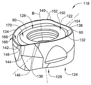
Attention is now drawn to Figs. 15 to 21 which show another embodiment of
the cutting insert. In these figures, like parts are designated with like
reference
numerals with the addition of 100. The cutting insert 118 shown in Figs. 15 to
21
has a structure similar to the structure of the cutting insert 18 described
above,
however, it differs in the shape of its cutting edges.
The cutting insert 118 comprises, in each end surface 128 thereof, first and
second main cutting edges 132, 134 that are connected, through extremities
thereof,
to first and second secondary cutting edges 144, 150.
The first main cutting edge 132 has a leading end 136 and a trailing end 138.
The second main cutting edge 134 has a leading end 140 and a trailing end 142.
A
first secondary cutting edge 144 merges, at a leading end 146 thereof, with
the
CA 02731559 2011-01-20
WO 2010/023659 PCT/IL2009/000814
-20-
leading end 136 of the first main cutting edge 132, and, at a trailing end 148
thereof, with the trailing end 142 of the second main cutting edge 134.
A second secondary cutting edge 150 merges, at a leading end 152 thereof,
with the leading end 140 of the second main cutting edge 134, and, at a
trailing end
154 thereof, with the trailing end 138 of the first main cutting edge 132.
In one embodiment, the first secondary cutting edge 144 may be identical to
the second secondary cutting edge 150. The first and second secondary cutting
edges 144, 150 are mainly used for performing ramp-down operations and their
length and shape are determined according to machining needs. In one
embodiment, the first main cutting edge 132 may be identical to the second
main
cutting edge 134.
As can be clearly seen in the figures, the leading end 136 of the first main
cutting edge 132 is located further from the median plane M than the trailing
end
138 of the first main cutting edge. Similarly, the leading end 140 of the
second
main cutting edge 134 is located further from the median plane M than the
trailing
end 142 of the second main cutting edge 134. Such a construction of the first
and
second main cutting edges 132, 134 provides the cutting insert 118 a highly
positive rake with respect to the upper central abutment surface 170.
Each of the first and second main cutting edges 132, 134 lies on a torus.
Furthermore, when the cutting insert is retained in the insert pocket 14 of
the
cutting tool 10, and the cutting tool is rotated about its axis of rotation A
by 360 ,
each point on an operative main cutting edge, i.e., first main cutting edge
132 or
second main cutting edge 134, sweeps out a portion of a torus.
The first and second main cutting edges 132, 134 and their associated first
and second secondary cutting edges 144, 150 form a continuously extending
cutting
edge 166 that is associated with a rake surface 168 that may extend
continuously
along the entire circumference of an end surface 128. As shown in Figs. 18 to
21,
the rake surface 168 merges with the upper central abutment surface 170
through
an undercut 90 which serves two purposes. First, it enables better control of
the
CA 02731559 2011-01-20
WO 2010/023659, PCT/IL2009/000814
-21-
chips produced during machining. Second, it enables better distinguishing of
the
upper central abutment surface 170 with respect to the upper surface 122 of
the
cutting insert 118, thus assuring satisfactory abutment properties of the
upper
central abutment surface 170. As can be seen in Figs. 19 to 21, the undercut
90
may vary in size and shape at different cross-sections of the cutting insert
118.
Similarly, the same may be applied to the lower surface 124 of the cutting
insert
118.
In the embodiments described above, the height orientation of the main
cutting edges 132, 134 with respect to the central abutment surface 170 is
such that
the cutting edges are higher than the central abutment surface, i.e., the
central
abutment surface 170 is located closer to the median plane M than the main
cutting
edges 132, 134. However, in other embodiments (not shown) the main cutting
edges 132, 134, or at least a portion thereof, may be located closer to the
median
plane M than the central abutment surface 170.
The construction of the cutting insert 118 enables considerable advantages
during machining, as can be appreciated by a person skilled in the art. The
highly
positive rake of the main cutting edges provides the operative main cutting
edge of
the cutting insert 118, when the cutting insert 118 is mounted in the cutting
tool 10
during machining, with a less negative rake angle, compared to the negative
rake
angle of the cutting insert 18 shown in Fig. 1 that is mounted in a negative
axial
positioning. The less negative axial rake leads to easier cutting, better chip
removal, lower cutting forces, and, lower power consumption. This construction
of
the cutting insert 118 may be used when it is required to machine relatively
high
tensile materials and high temperature alloys. A further advantage in this
case may
be avoiding adhesion of the chips.
Attention is now drawn to Fig. 22 which shows another embodiment of the
cutting insert. In this figure, like parts are designated with like reference
numerals
with the addition of 200.
As shown, a cutting insert 218 comprises two end surfaces 228 and a
CA 02731559 2011-01-20
WO 2010/023659 PCT/IL2009/000814
-22-
peripheral surface 226 extending therebetween. One of the end surfaces 228
forms
an upper surface 222 similar to the upper surface 122 of the cutting insert
118
described above, and, another end surface forms a lower surface 224 of the
cutting
insert 218. The upper surface 222 comprises a continuously extending
peripheral
cutting edge 266 associated with a continuously extending rake surface 268.
The cutting edge 266 comprises two curved cutting edges, namely, a first
main cutting edge 232 and a second main cutting edge 234, and, two straight
cutting edges, namely, a first secondary cutting edge 244 and a second
secondary
cutting edge 250 connecting between extremities of the first and second main
cutting edges 232, 234 (the first secondary cutting edge 244 is not shown).
In order to better cut ductile materials, the rake surface 268 if formed
considerably larger than the rake surface 168 of the cutting insert 118. The
rake
surface 268 is slanted at a rake slant angle ? with respect to the lower
surface 224
of the cutting insert 218. The rake slant angle k is relatively large and is
preferably
equal to or greater than 25 .
A rake inner extremity 92 is defined at a region where an innermost extremity
of the rake surface 268 merges with a bore peripheral region 94 that surrounds
the
through bore 30. The bore peripheral region 94 merges with the through bore 30
at
a bore upper end 96 and it extends generally parallel to the lower surface 224
of the
cutting insert 218. A first rake length H1 is defined between a given point 98
on
the peripheral cutting edge 266 and the rake inner extremity 92, measured in a
plane parallel to the lower surface 224. A second rake length H2 is defined
between the same given point 98 on the peripheral cutting edge 266 and the
bore
upper end 96, measured in a plane parallel to the lower surface 224.
A rake extension ratio E is defined as a ratio between the first rake length
H1
and the second rake length H2. The rake extension ratio E may vary within a
preferable range. According to one embodiment, the rake extension ratio E is
smaller than 1 and equal to or greater than 0.8.
Since the rake surface 268 is relatively very large, it extends, in an inward
CA 02731559 2011-01-20
WO 2010/023659 PCT/IL2009/000814
-23-
direction of the cutting insert 218, almost to the through bore 30. With such
a
construction, the upper surface 222 lacks a central abutment surface, in
contrary to
the existence of the central abutment surface 170 in the upper surface 122 of
the
cutting insert 118.
Thus, since the cutting insert 218 lacks a central abutment surface, it cannot
be used as a double sided cutting insert. Therefore, the lower surface 224 of
the
cutting insert 118 lacks cutting edges, and is formed flat in order to serve
solely as
an abutment surface. Accordingly, the peripheral surface 226 is formed only
with
the abutment surfaces required for abutment of a single sided cutting insert,
namely, the first pair of side abutment surfaces 258, and, the third pair of
side
abutment surfaces 262 (not shown).
Although the present invention has been described to a certain degree of
particularity, it should be understood that various alterations and
modifications
could be made without departing from the spirit or scope of the invention as
hereinafter claimed.
The cutting insert is not limited to have two main cutting edges on each end
surface. In one embodiment (not shown), the cutting insert is provided with
three
main cutting edges which are connected, at extremities thereof, by three
secondary
cutting edges. The three main cutting edges may be identical. Likewise, the
three
secondary cutting edges may be identical.
In one embodiment (not shown), the cutting insert is provided with four main
cutting edges which are connected, at extremities thereof, by four secondary
cutting
edges. The four main cutting edges may be identical. Likewise, the four
secondary
cutting edges may be identical.
Thus, a cutting insert according to the present invention may be retained by a
clamping screw passing through a through bore. The cutting insert may have
four,
six or eight rounded cutting edges, wherein the cutting insert may be indexed
four,
six or eight times. The cutting edges may extend along a large arc and may
extend
at an angle larger than 120 .